
Related Manuals for National Instruments NI PXIe-1085


Summary of Contents for National Instruments NI PXIe-1085
- Page 1 PXI Express NI PXIe-1085 Series User Manual NI PXIe-1085 Series User Manual January 2017 373712H-01...
- Page 2 11500 North Mopac Expressway Austin, Texas 78759-3504 USA Tel: 512 683 0100 For further support information, refer to the NI Services appendix. To comment on NI documentation, refer to the NI website at and enter the Info Code ni.com/info feedback © 2012–2017 National Instruments. All rights reserved.
-
Page 3: Legal Information
National Instruments Corporation. National Instruments respects the intellectual property of others, and we ask our users to do the same. NI software is protected by copyright and other intellectual property laws. Where NI software may be used to reproduce software or other materials belonging to others, you may use NI software only to reproduce materials that you may reproduce in accordance with the terms of any applicable license or other legal restriction. - Page 4 ™ The ExpressCard word mark and logos are owned by PCMCIA and any use of such marks by National Instruments is under license. The mark LabWindows is used under a license from Microsoft Corporation. Windows is a registered trademark of Microsoft Corporation in the United States and other countries.
-
Page 5: Table Of Contents
Rack Mount Kit ......................1-5 Slot Blockers......................1-5 Replacement Power Supply..................1-5 Replacement Fan Modules ..................1-5 NI PXIe-1085 Series Backplane Overview ..............1-5 Interoperability with CompactPCI................1-5 System Controller Slot....................1-6 NI PXIe-1085 12 GB/s ..................1-6 NI PXIe-1085 24 GB/s ..................1-7 Hybrid Peripheral Slots .................... - Page 6 Contents Installing Peripheral Modules ...................2-8 Remote System Monitoring ....................2-9 Default Configuration Settings ................. 2-10 Front Panel and Fan Module LED Indicators ..............2-11 Remote Voltage Monitoring and Control ................. 2-12 Inhibit Mode Switch ......................2-14 PXI_CLK10 Front Panel Connectors ................2-14 PXI Express System Configuration with MAX..............
-
Page 7: About This Manual
About This Manual The NI PXIe-1085 Series User Manual describes the features of the NI PXIe-1085 Series chassis and contains information about configuring the chassis, installing the modules, and operating the chassis. Related Documentation The following documents contain information that you might find helpful as you read this manual: •... -
Page 8: Getting Started
Getting Started This chapter describes the key features of the NI PXIe-1085 Series chassis and lists the kit contents and optional equipment you can order from National Instruments. Unpacking Carefully inspect the shipping container and the chassis for damage. Check for visible damage to the metal work. -
Page 9: Key Features
The chassis’ modular design ensures a high level of maintainability, resulting in a very low mean time to repair (MTTR). The NI PXIe-1085 Series chassis fully complies with the PXI-5 PXI Express Hardware Specification, offering advanced timing and synchronization features. -
Page 10: Chassis Description
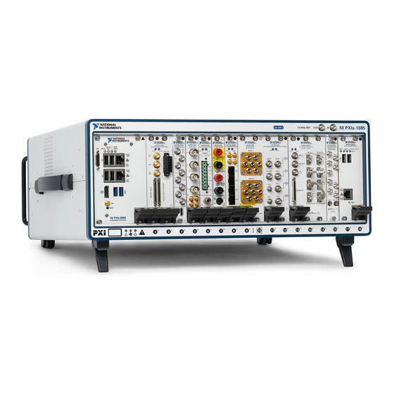
Replacement fan modules Chassis Description Figures 1-1 and 1-2 show the key features of the NI PXIe-1085 Series chassis front and back panels. Figure 1-1 shows the front view of the series chassis. Figure 1-2 shows the rear view of the series chassis. - Page 11 Chapter 1 Getting Started Figure 1-1. Front View of the NI PXIe-1085 Series Chassis NI PXIe-1085 12 11 Chassis Carry Handle PXI Express Hybrid Peripheral Slots (16x) Backplane Connectors PXI Express System Timing Slot 10 MHz REF OUT SMA 10 PXI Express System Controller Slot...
-
Page 12: Optional Equipment
Rack Mount Kit There are two required kits for mounting the NI PXIe-1085 Series chassis into a rack. The first is a pair of mounting brackets for use on the front of the chassis. The second is a rear rack mount kit. -
Page 13: System Controller Slot
PCI Express-to-PCI bridges to provide PCI buses to the hybrid peripheral slots. Refer to Figure 1-3 for an overview of the NI PXIe-1085 Series architecture. System slot link 1 is a Gen-2 x8 PCI Express link to PCI Express switch 1, providing a nominal bandwidth of 4 GB/s (single direction) between the system controller and PCI Express switch 1. -
Page 14: Ni Pxie-1085 24 Gb/S
PCI Express-to-PCI bridges to provide PCI buses to the hybrid peripheral slots. Refer to Figure 1-3 for an overview of the NI PXIe-1085 Series architecture. System slot link 1 is a Gen-3 x8 PCI Express link to PCI Express switch 1, providing a nominal bandwidth of 8 GB/s (single direction) between the system controller and PCI Express switch 1. -
Page 15: Hybrid Peripheral Slots
• NI PXIe-1085 12 GB/s—A PXI Express peripheral with x8, x4, or x1 PCI Express link through a switch to the system slot. Each PXI Express peripheral slot can link up to a Gen-2 x8 PCI Express, providing a maximum nominal single-direction bandwidth of 4 GB/s. -
Page 16: System Timing Slot
• NI PXIe-1085 12 GB/s—A PXI Express System Timing Module with x8, x4, or x1 PCI Express link to the system slot through a PCI Express switch. Each PXI Express peripheral slot can link up to a Gen-2 x8 PCI Express, providing a maximum nominal single-direction bandwidth of 4 GB/s. -
Page 17: Pxi Local Bus
Chapter 1 Getting Started The system timing slot has a pin (PXIe_SYNC_CTRL) through which a system timing module can control the PXIe_SYNC100 timing. Refer to the PXI Express Specification and the PXIe_SYNC_CTRL section of this chapter for details. Figure 1-5. PXI Express Star Connectivity Diagram STAR STAR 10 DSTAR 1... -
Page 18: System Reference Clock
Bridge #1 Bridge #2 System Reference Clock The NI PXIe-1085 Series chassis supplies PXI_CLK10, PXIe_CLK100, and PXIe_SYNC100 independently driven to each peripheral slot. An independent buffer (having a source impedance matched to the backplane and a skew of less than 1 ns between slots) drives PXI_CLK10 to each slot. You can use this common reference clock signal to synchronize multiple modules in a measurement or control system. - Page 19 Chapter 1 Getting Started on this pin, the backplane automatically phase-locks the PXI_CLK10, PXIe_CLK100, and PXIe_SYNC100 signals to this external clock and distributes these signals to the slots. Refer to Appendix A, Specifications, for the specification information for an external clock provided on the PXI_CLK10_IN pin of the system timing slot.
-
Page 20: Pxie_Sync_Ctrl
NI PXIe-1085 Series User Manual PXIe_SYNC_CTRL PXIe_SYNC100 is by default a 10 ns pulse synchronous to PXI_CLK10. The frequency of PXIe_SYNC100 is 10/n MHz, where n is a positive integer. The default for n is 1, giving PXIe_SYNC100 a 100 ns period. However, the backplane allows n to be programmed to other integers. -
Page 21: Installation And Configuration
Installation and Configuration This chapter describes how to prepare and operate the NI PXIe-1085 Series chassis. Before connecting the chassis to a power source, read this chapter and the Read Me First: Safety and Electromagnetic Compatibility document included with your kit. -
Page 22: Chassis Cooling Considerations
Installation and Configuration Chassis Cooling Considerations The NI PXIe-1085 Series chassis is designed to operate on a bench or in an instrument rack. The chassis must be oriented horizontally for benchtop use. Vertical orientation with the chassis handle up is not a supported configuration. Regardless of the configuration, you must provide the cooling clearances as outlined in the following sections. - Page 23 NI PXIe-1085 Series User Manual Figure 2-2. NI PXIe-1085 Series Chassis Vents Primary Air Intake Vent (3x) Secondary Air Intake/Exhaust Vents (Both Sides) Primary Air Exhaust Vent © National Instruments | 2-3...
-
Page 24: Chassis Ambient Temperature Definition
Front Panel and Fan Module LED Indicators section of this chapter. Setting Fan Speed The fan-speed selector switch is on the rear panel of the NI PXIe-1085 Series chassis. Refer to Figure 1-2, Rear View of the NI PXIe-1085 Series Chassis, to locate the fan-speed selector switch. -
Page 25: Securing Front Panel
NI PXIe-1085 Series chassis in an instrument rack. Refer to Figure A-3, NI Chassis Rack Mount Components. You may want to remove the feet from the NI PXIe-1085 Series chassis when Note rack mounting. To do so, remove the screws holding the feet in place. -
Page 26: Connecting Safety Ground
Chapter 2 Installation and Configuration Connecting Safety Ground The NI PXIe-1085 Series chassis are designed with a three-position Caution NEMA 5-15 style plug for the U.S. that connects the ground line to the chassis ground. To minimize shock hazard, make sure the electrical power outlet you use to power the chassis has an appropriate earth safety ground. -
Page 27: Installing A Pxi Express System Controller
This section contains general installation instructions for installing a PXI Express system controller in a NI PXIe-1085 Series chassis. Refer to your PXI Express system controller user manual for specific instructions and warnings. To install a system controller, complete the... -
Page 28: Installing Peripheral Modules
NI PXIe-1085 Series chassis. You can place CompactPCI, CompactPCI Express, PXI, or PXI Express modules in other slots depending on the slot type. Figure 2-5. NI PXI Express System Controller Installed in a NI PXIe-1085 Series Chassis NI PXIe-1085 Series Chassis... -
Page 29: Remote System Monitoring
Injector/Ejector Rail Remote System Monitoring The NI PXIe-1085 Series chassis provides an Ethernet port on the rear panel of the chassis. You can use this Ethernet port to monitor the chassis operating parameters remotely over a network. Refer to Figure 1-2,... -
Page 30: Default Configuration Settings
Chapter 2 Installation and Configuration The Ethernet controller can perform automatic crossover, thus eliminating the Note need for crossover cables. Through the remote monitoring Ethernet interface of the chassis, you can access a web page with information about the current chassis operating parameters. You can access this page in most browsers. -
Page 31: Front Panel And Fan Module Led Indicators
NI PXIe-1085 Series User Manual Front Panel and Fan Module LED Indicators Figure 2-8 shows the front panel LEDs. Table 2-2 describes the LED states. Figure 2-8. Front Panel LEDs Temperature LED Fan LED Power LED Table 2-2. Front Panel LED States... -
Page 32: Remote Voltage Monitoring And Control
Remote Voltage Monitoring and Control The NI PXIe-1085 Series chassis supports remote voltage monitoring and inhibiting through a female 8-pin connector on the rear panel. Table 2-4 shows the pinout of the 8-pin connector. The NI PXIe-1085 Series chassis accessory kit includes one 8-pin connector. - Page 33 You can use a digital voltmeter to ensure all voltage levels in the NI PXIe-1085 Series chassis are within the allowable limits. Referring to Table 2-5, connect one lead of the voltmeter to a supply pin on the 8-pin remote voltage monitoring connector on the rear panel.
-
Page 34: Inhibit Mode Switch
Inhibit Mode switch must be in the Manual position. PXI_CLK10 Front Panel Connectors There are two SMA connectors on the front of the NI PXIe-1085 Series chassis for PXI_CLK10. The connectors are labeled IN and OUT. You can use them for supplying the backplane with PXI_CLK10 or routing the backplane’s PXI_CLK10 to another chassis. -
Page 35: Pxi Express System Configuration With Max
NI PXIe-1085 Series User Manual PXI Express System Configuration with MAX The PXI Platform Services software included with your chassis automatically identifies your PXI Express system components to generate a file. You can configure your pxiesys.ini entire PXI system and identify PXI-1 chassis through Measurement & Automation Explorer (MAX), included with your system controller. -
Page 36: Trigger Configuration In Max
Dynamic reservation/routing/deallocation is on the fly within a user program based upon National Instruments APIs such as NI-DAQmx. Static reservation of trigger lines can be implemented by the user in MAX through the Triggers tab. -
Page 37: Using System Configuration And Initialization Files
System controllers from NI provide the pxisys.ini file for the NI PXIe-1085 Series chassis, so you should not need to use the pxisys.ini file. Refer to the documentation provided with the system controller or chassis.ini for more information on files. -
Page 38: Maintenance
Maintenance This chapter describes basic maintenance procedures you can perform on the NI PXIe-1085 Series chassis. Disconnect the power cable prior to servicing a NI PXIe-1085 Series Caution chassis. Service Interval Clean dust from the chassis exterior (and interior) as needed, based on the operating environment. -
Page 39: Exterior Cleaning
Resetting the AC Mains Circuit Breaker If the NI PXIe-1085 Series chassis is connected to an AC source and encounters an over-current condition, the circuit breaker on the rear panel will trip to prevent damage to the chassis. -
Page 40: Replacing The Modular Power Supply
First: Safety and Electromagnetic Compatibility document included with the kit. Removal The NI PXIe-1085 Series power supply is a replacement part for the NI PXIe-1085 Series chassis. Before attempting to replace the power supply, verify that there is adequate clearance behind the chassis. - Page 41 Chapter 3 Maintenance Figure 3-1. Removing Power Supply Shuttle Power Supply Shuttle Mounting Screws (8x) NI PXIe-1085 Series Chassis Power Supply Shuttle Shuttle Rail Safety Catch (Both Sides) Modular Power Supply Screws (4x) 3-4 | ni.com...
-
Page 42: Installation
The fan-speed selector switch is on the rear panel of the power supply shuttle. Refer to Figure 1-2, Rear View of the NI PXIe-1085 Series Chassis, to locate the fan-speed selector. Select High for maximum cooling performance (recommended) or Auto for quieter operation. -
Page 43: Connecting Safety Ground
Chapter 3 Maintenance Connecting Safety Ground Refer to the Connecting Safety Ground section of Chapter 2, Installation and Configuration. Connecting to Power Source Refer to the Connecting to Power Source section of Chapter 2, Installation and Configuration. Installing Replacement Fan Modules Follow these steps to remove a failed fan module: Pinch both snaps at the top of the fan module simultaneously. - Page 44 NI PXIe-1085 Series User Manual Figure 3-3. Replacing Fan Module Fan Module Snaps Fan Module © National Instruments | 3-7...
-
Page 45: Appendix A Specifications
Specifications This appendix contains specifications for the NI PXIe-1085 Series chassis. Specifications are subject to change without notice. Caution Electrical AC Input Input voltage range ........... 100 VAC to 240 VAC Operating voltage range ........90 VAC to 264 VAC Input frequency.......... - Page 46 62 A 62 A -12 V 5 VAUX Maximum total available power for the NI PXIe-1085 12 GB/s is 791 W. Note Maximum total available power for the NI PXIe-1085 24 GB/s is 775 W. Backplane slot current capacity Slot...
- Page 47 NI PXIe-1085 Series User Manual Load regulation Voltage Load Regulation +3.3 V <5% +12 V <5% +5 V <5% -12 V <5% Maximum ripple and noise (20 MHz bandwidth) Voltage Maximum Ripple and Noise +3.3 V 50 mVpp +12 V...
-
Page 48: Operating Environment
Appendix A Specifications Chassis Cooling Module cooling system NI PXIe-1085 Series chassis.....Forced air circulation (positive pressurization) through three 169 cfm fans with High/Auto speed selector Slot airflow direction ........Bottom of module to top of module Module cooling intake ........Bottom rear of chassis Module cooling exhaust........Along both sides and top of chassis... -
Page 49: Shock And Vibration
Sound Power Auto fan (up to ~30 °C ambient) ...... 60.8 dBA High fan ............75.9 dBA The protection provided by the NI PXIe-1085 Series can be impaired if it Caution is used in a manner not described in this document. - Page 50 Appendix A Specifications • AS/NZS CISPR 22: Class A emissions • FCC 47 CFR Part 15B: Class A emissions • ICES-001: Class A emissions In the United States (per FCC 47 CFR), Class A equipment is intended for use Note in commercial, light-industrial, and heavy-industrial locations.
- Page 51 At the end of the product life cycle, all products must be sent to EU Customers a WEEE recycling center. For more information about WEEE recycling centers, National Instruments WEEE initiatives, and compliance with WEEE Directive 2002/96/EC on Waste and Electronic Equipment, visit ni.com/environment/...
- Page 52 Appendix A Specifications 100 MHz System Reference Clock: PXIe_CLK100 and PXIe_SYNC100 Maximum slot-to-slot skew ......100 ps Accuracy ............±25 ppm max. (guaranteed over the operating temperature range) Maximum jitter ..........3 ps RMS phase-jitter (10 Hz to 12 kHz range); 2 ps RMS phase-jitter (12 kHz to 20 MHz range) Duty-factor for PXIe_CLK100 ......45% to 55% Absolute single-ended voltage swing (When each line in the differential pair...
- Page 53 Notes 24 GB/s PCI Express Backplane Diagram section of Chapter 1, Getting Started. For other specifications, the NI PXIe-1085 Series chassis complies with the PXI-5 PXI Express Hardware Specification. Mechanical Overall dimensions Standard chassis Height ..........6.97 in. (177.1 mm) Width ..........
- Page 54 Appendix A Specifications Figures A-1 and A-2 show the NI PXIe-1085 Series chassis dimensions. The holes shown are for the installation of the optional rack mount kits. You can install those kits on the front or rear of the chassis, depending on which end of the chassis you want to face toward the front of the instrument cabinet.
- Page 55 NI PXIe-1085 Series User Manual Figure A-2. NI PXIe-1085 Series Chassis Dimensions (Bottom) Dimensions are in inches (millimeters) 14.51 (368.5) 1.47 (37.4) 15.39 (390.9) 1.07 (27.3) © National Instruments | A-11...
- Page 56 Appendix A Specifications Figure A-3 shows the chassis rack mount kit components. Figure A-3. NI Chassis Rack Mount Kit Components Front Rack Mount Kit NI PXIe-1085 Series Chassis Rear Rack Mount Kit A-12 | ni.com...
- Page 57 Pinouts This appendix describes the connector pinouts for the NI PXIe-1085 Series chassis backplane. Table B-1 shows the XP1 Connector Pinout for the System Controller slot. Table B-2 shows the XP2 Connector Pinout for the System Controller slot. Table B-3 shows the XP3 Connector Pinout for the System Controller slot.
- Page 58 Appendix B Pinouts System Controller Slot Pinouts Table B-1. XP1 Connector Pinout for the System Controller Slot Pins Signals 3.3V Table B-2. XP2 Connector Pinout for the System Controller Slot 2PETp1 2PETn1 2PERp1 2PERn1 2PETp2 2PETn2 2PETp3 2PETn3 2PERp3 2PERn3 2PERp2 2PERn2 2PETp4...
- Page 59 NI PXIe-1085 Series User Manual Table B-3. XP3 Connector Pinout for the System Controller Slot PWR_OK PS_ON# LINKCAP PWRBTN# SMBDAT SMBCLK RSVD RSVD RSVD RSVD PERST# 2RefClk+ 2RefClk- 1RefClk+ 1RefClk- 1PETp0 1PETn0 1PERp0 1PERn0 1PETp1 1PETn1 1PETp2 1PETn2 1PERp2 1PERn2...
- Page 60 System Timing Slot Pinouts Table B-5. TP1 Connector Pinout for the System Timing Slot PXIe_DSTARA3+ PXIe_DSTARA3- PXIe_DSTARC4+ PXIe_DSTARC4- PXI_STAR12 PXI_STAR13 PXIe_DSTARB4+ PXIe_DSTARB4- PXIe_DSTARA4+ PXIe_DSTARA4- PXIe_DSTARC5+ PXIe_DSTARC5- PXI_STAR14 PXI_STAR15 PXIe_DSTARB5+ PXIe_DSTARB5- PXIe_DSTARA5+ PXIe_DSTARA5- PXIe_DSTARC6+ PXIe_DSTARC6- PXI_STAR16 PXIe_DSTARB6+ PXIe_DSTARB6- PXIe_DSTARA6+ PXIe_DSTARA6-...
- Page 61 Table B-6. TP2 Connector Pinout for the System Timing Slot PXIe_DSTARC8+ PXIe_DSTARC8- PXIe_DSTARB8+ PXIe_DSTARB8- PXIe_DSTARA8+ PXIe_DSTARA8- PXIe_DSTARC1+ PXIe_DSTARC1- PXIe_DSTARB1+ PXIe_DSTARB1- PXI_STAR0 PXI_STAR1 PXIe_DSTARA1+ PXIe_DSTARA1- PXI_STAR2 PXI_STAR3 PXIe_DSTARC2+ PXIe_DSTARC2- PXI_STAR4 PXI_STAR5 PXIe_DSTARB2+ PXIe_DSTARB2- PXI_STAR6 PXI_STAR7 PXIe_DSTARA2+ PXIe_DSTARA2- PXI_STAR8 PXI_STAR9 PXIe_DSTARC11+ PXIe_DSTARC11- PXIe_DSTARC3+ PXIe_DSTARC3- PXI_STAR10...
- Page 62 Table B-7. XP3 Connector Pinout for the System Timing Slot PXIe_CLK100+ PXIe_CLK100- PXIe_SYNC100+ PXIe_SYNC100- PXIe_DSTARC+ PXIe_DSTARC- PRSNT# PWREN# PXIe_DSTARB+ PXIe_DSTARB- PXIe_DSTARA+ PXIe_DSTARA- SMBDAT SMBCLK MPWRGD* PERST# 1RefClk+ 1RefClk- 1PETp0 1PETn0 1PERp0 1PERn0 1PETp1 1PETn1 1PETp2 1PETn2 1PERp2 1PERn2 1PERp1 1PERn1 1PETp3 1PETn3 1PERp3...
- Page 63 NI PXIe-1085 Series User Manual Table B-8. XP4 Connector Pinout for the System Timing Slot 5Vaux SYSEN# WAKE# ALERT# 3.3V 3.3V 3.3V PXI_TRIG3 PXI_TRIG4 PXI_TRIG5 PXI_TRIG6 PXI_TRIG2 ATNLED PXI_CLK10_IN PXI_CLK10 PXI_TRIG1 PXI_TRIG0 ATNSW# PXI_TRIG7 PXIe_SYNC_CTRL PXI_LBL6 PXI_LBR6 Peripheral Slot Pinouts Table B-9.
- Page 64 Appendix B Pinouts Table B-9. P1 Connector Pinout for the Peripheral Slot (Continued) INTA# INTB# INTC# INTD# -12V TRST# +12V Table B-10. P2 Connector Pinout for the Peripheral Slot PXI_LBR0 PXI_LBR1 PXI_LBR2 PXI_LBR3 PXI_LBR4 PXI_LBR5 PXI_LBL0 PXI_LBL1 PXI_LBL2 PXI_LBL3 PXI_LBL4 PXI_LBL5 PXI_TRIG3 PXI_TRIG4...
- Page 65 NI PXIe-1085 Series User Manual Hybrid Slot Pinouts Table B-11. P1 Connector Pinout for the Hybrid Slot REQ64# ENUM# 3.3V AD[1] V(I/O) AD[0] ACK64# 3.3V AD[4] AD[3] AD[2] AD[7] 3.3V AD[6] AD[5] 3.3V AD[9] AD[8] M66EN C/BE[0]# AD[12] V(I/O) AD[11] AD[10] 3.3V...
- Page 66 Table B-12. XP3 Connector Pinout for the Hybrid Slot PXIe_CLK100+ PXIe_CLK100- PXIe_SYNC100+ PXIe_SYNC100- PXIe_DSTARC+ PXIe_DSTARC- PRSNT# PWREN# PXIe_DSTARB+ PXIe_DSTARB- PXIe_DSTARA+ PXIe_DSTARA- SMBDAT SMBCLK MPWRGD* PERST# 1RefClk+ 1RefClk- 1PETp0 1PETn0 1PERp0 1PERn0 1PETp1 1PETn1 1PETp2 1PETn2 1PERp2 1PERn2 1PERp1 1PERn1 1PETp3 1PETn3 1PERp3 1PERn3...
- Page 67 The licenses for most software are designed to take away your freedom to share and change it. By contrast, the GNU General Public Licenses are intended to guarantee your freedom to share and change free software—to make sure the software is free for all its users. © National Instruments | C-1...
- Page 68 Appendix C Documentation Notice for MiniXML This license, the Library General Public License, applies to some specially designated Free Software Foundation software, and to any other libraries whose authors decide to use it. You can use it for your libraries, too. When we speak of free software, we are referring to freedom, not price.
- Page 69 NI PXIe-1085 Series User Manual Because of this blurred distinction, using the ordinary General Public License for libraries did not effectively promote software sharing, because most developers did not use the libraries. We concluded that weaker conditions might promote sharing better.
- Page 70 Appendix C Documentation Notice for MiniXML You may copy and distribute verbatim copies of the Library’s complete source code as you receive it, in any medium, provided that you conspicuously and appropriately publish on each copy an appropriate copyright notice and disclaimer of warranty; keep intact all the notices that refer to this License and to the absence of any warranty;...
- Page 71 NI PXIe-1085 Series User Manual Public License has appeared, then you can specify that version instead if you wish.) Do not make any other change in these notices. Once this change is made in a given copy, it is irreversible for that copy, so the ordinary GNU General Public License applies to all subsequent copies and derivative works made from that copy.
- Page 72 Appendix C Documentation Notice for MiniXML You must give prominent notice with each copy of the work that the Library is used in it and that the Library and its use are covered by this License. You must supply a copy of this License.
- Page 73 NI PXIe-1085 Series User Manual You may not copy, modify, sublicense, link with, or distribute the Library except as expressly provided under this License. Any attempt otherwise to copy, modify, sublicense, link with, or distribute the Library is void, and will automatically terminate your rights under this License.
- Page 74 Appendix C Documentation Notice for MiniXML 13. The Free Software Foundation may publish revised and/or new versions of the Library General Public License from time to time. Such new versions will be similar in spirit to the present version, but may differ in detail to address new problems or concerns. Each version is given a distinguishing version number.
- Page 75 NI PXIe-1085 Series User Manual To apply these terms, attach the following notices to the library. It is safest to attach them to the start of each source file to most effectively convey the exclusion of warranty; and each file should have at least the “copyright”...
- Page 76 NI Services National Instruments provides global services and support as part of our commitment to your success. Take advantage of product services in addition to training and certification programs that meet your needs during each phase of the application life cycle; from planning and development through deployment and ongoing maintenance.
- Page 77 Appendix D NI Services • Training and Certification—The NI training and certification program is the most effective way to increase application development proficiency and productivity. Visit for more information. ni.com/training – The Skills Guide assists you in identifying the proficiency requirements of your current application and gives you options for obtaining those skills consistent with your time and budget constraints and personal learning preferences.
- Page 78 Symbols ° Degrees. ≥ Equal or greater than. ≤ Equal or less than. Percent. Amperes. Alternating current. ANSI American National Standards Institute. Auto Automatic fan speed control. American Wire Gauge. © National Instruments | G-1...
- Page 79 Glossary backplane An assembly, typically a printed circuit board, with connectors and signal paths that bus the connector pins. Celsius. Cubic feet per minute. Code of Federal Regulations. Centimeters. CompactPCI An adaptation of the Peripheral Component Interconnect (PCI) Specification 2.1 or later for industrial and/or embedded applications requiring a more robust mechanical form factor than desktop PCI.
- Page 80 NI PXIe-1085 Series User Manual Electromagnetic Compatibility. Electromagnetic Interference. Federal Communications Commission. filler panel A blank module front panel used to fill empty slots in the chassis. (1) grams; (2) a measure of acceleration equal to 9.8 m/s GPIB General Purpose Interface Bus (IEEE 488).
- Page 81 Glossary jitter A measure of the small, rapid variations in clock transition times from their nominal regular intervals. Units: seconds RMS. Kilograms. Kilometers. Pounds. Light emitting diode. line regulation The maximum steady-state percentage that a DC voltage output will change as a result of a specified change in input AC voltage (step change from 90 to 132 VAC or 180 to 264 VAC).
- Page 82 NI PXIe-1085 Series User Manual NEMA National Electrical Manufacturers Association. National Instruments. power supply shuttle A removable module that contains the chassis power supply. PCI eXtensions for Instrumentation. PXI_CLK10 10 MHz PXI system reference clock. Relative humidity. Root mean square.
- Page 83 Glossary system reference A 10 MHz clock, also called PXI_CLK10, that is distributed to all clock peripheral slots in the chassis, as well as a BNC connector on the rear of chassis labeled 10 MHz REF OUT. The system reference clock can be used for synchronization of multiple modules in a measurement or control system.
- Page 84 2-4 connector pinouts. See pinouts high vibration environment, 2-4 cooling installing a PXI Express system air cooling of NI PXIe-1085 series controller, 2-7 chassis, 2-2 peripheral module installation, 2-8 filler panel installation, 2-4 PXI Express configuration in...
- Page 85 P1 connector (table), B-7 front panel LED states (table), 2-11 P2 connector (table), B-8 pinouts, B-1 8-pin connector (table), 2-13 power cables (table), 1-2 maintenance of NI PXIe-1085 chassis, 3-1 power supply cleaning connecting to, 2-6 exterior cleaning, 3-2 remote voltage monitoring and...
- Page 86 NI PXIe-1085 Series User Manual storage environment, A-4 external clock source, A-8 rack mount kit dimensions (figure), A-12 mechanical, A-9 rack mounting, 2-5 PXI differential star triggers kit, 1-5 (PXIe-DSTARA, PXIe-DSTARB, rear 8-pin connector PXIe-DSTARC), A-9 pinout (table), 2-13 PXI star trigger, A-8...
Need help?
Do you have a question about the NI PXIe-1085 and is the answer not in the manual?
Questions and answers