Advertisement
Quick Links
Advertisement

Subscribe to Our Youtube Channel
Related Manuals for National Instruments PXIe-1082DC


Summary of Contents for National Instruments PXIe-1082DC
- Page 1 PXIe-1082DC...
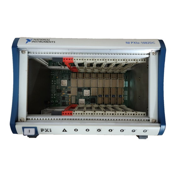
- Page 2 INSTALLATION GUIDE 8-Slot PXI Backplane This guide describes installation requirements for the 8-slot PXI backplane, shown in Figure 1. Figure 1. 8-Slot PXI Backplane...
-
Page 3: Mechanical Requirements
Figure 4 for the position of the mounting holes. Cooling Note National Instruments is not responsible for damage to the backplane if inadequate cooling is used. You should mount a fan below the backplane. Airflow should be from the bottom to the top of the PXI modules. You must determine the airflow requirements for your system based on the PXI Hardware Specification. - Page 4 PXI chassis before removing the backplane from the packaging. Dimensions 1.132 [28.752] .142 [3.607] .122 [3.100] 4.945 [125.60] .122 [3.100] .703 .800 [17.856] [20.320] 9.336 [237.13] Figure 2. Dimensions © National Instruments Corporation 8-Slot PXI Backplane Installation Guide...
-
Page 5: Electrical Requirements
Electrical Requirements PXI Connectors The PXI connectors (J11-J18, J2-J9) have pin descriptions defined in the PXI hardware Specification. The connectors are shown in Figure 3. 1 Slot 1 (Controller Slot) 2 Slot 2 (Star Trigger Slot) 3 Slots 3-8 (Peripheral Slots) Figure 3. - Page 6 Note The system slot (slot 1) receives +12 V power from pin 17 of J20. If this pin is not connected to +12 V the system controller will not function properly. © National Instruments Corporation 8-Slot PXI Backplane Installation Guide...
- Page 7 Table 1. Connector J20 Pin Descriptions Required for Basic Connector Signal Description Power-up +3.3 V Backplane +3.3 V power plane. Backplane ground plane. +3.3 V Backplane +3.3 V power plane. LED2 Connects to pin 8 of J21. INHIBIT Connects to pin 7 of J21. LED1 Connects to pin 5 of J21.
- Page 8 LED1 Connects to pin 6 of J20. Connects to backplane’s +5V power plane. Connects to pin 5 of J20. LED2 Connects to pin 4 of J20. Connects to backplane’s ground plane. © National Instruments Corporation 8-Slot PXI Backplane Installation Guide...
- Page 9 Backplane Size ............3U-sized; one system slot (with three system expansion slots) and seven peripheral slots. Compliant with IEEE 1101.10 mechanical packaging. PXI Specification Revision 2.0 compliant. Accepts both PXI and CompactPCI (PICMG 2.0 R 3.0) 3U modules. Backplane bare-board material ....UL 94 V-0 Recognized Backplane connectors ......Conforms to IEC 917 and IEC 1076-4-101, and are UL 94 V-0 rated...
- Page 10 External clock output Connector........Connector J1 on rear of backplane (ground-referenced) ±20% squarewave into 50 Ω Output amplitude ......1 V into open circuit Output impedance ......50 Ω ± 5 Ω © National Instruments Corporation 8-Slot PXI Backplane Installation Guide...
- Page 11 Instruments trademarks. Other product and company names mentioned herein are trademarks or trade names of their respective companies. For patents covering National Instruments products, refer to the appropriate location: Help»Patents in your software, the patents.txt file on your CD, or ni.com/patents.
Need help?
Do you have a question about the PXIe-1082DC and is the answer not in the manual?
Questions and answers