Table of Contents
Advertisement
Quick Links
INSTALLATION GUIDE
8-Slot NI PXIe-1082 Backplane
Contents
This guide describes installation requirements for the 8-slot NI PXIe-1082
backplane.
NI PXIe-1082 Backplane Overview ....................................................... 2
Interoperability with CompactPCI................................................... 3
System Controller Slot..................................................................... 3
Hybrid Peripheral Slots.................................................................... 4
PXI Express Peripheral Slots ........................................................... 4
System Timing Slot ......................................................................... 4
PXI Local Bus.................................................................................. 6
PXI Trigger Bus............................................................................... 6
System Reference Clock .................................................................. 7
PXIe_SYNC_CTRL ........................................................................ 9
Mechanical Requirements....................................................................... 10
Mounting.......................................................................................... 10
Dimensions ...................................................................................... 11
Cooling............................................................................................. 11
Handling.................................................................................................. 12
Electrical Requirements .......................................................................... 13
PXI Connectors................................................................................ 13
Power ............................................................................................... 14
Connector J37 ........................................................................... 14
Connector J36 ........................................................................... 16
Connector J35 ........................................................................... 16
Connectors J2, J3, and J4.......................................................... 17
Backplane Specifications ................................................................. 17
PXIe_SYNC100) Specifications................................................... 18
10 MHz System Reference Clock: PXI_CLK10 ...................... 18
PXIe_SYNC100 .................................................................... 18
External Clock Source .............................................................. 19
Advertisement
Table of Contents

Related Manuals for National Instruments NI PXIe-1082


Summary of Contents for National Instruments NI PXIe-1082
-
Page 1: Table Of Contents
INSTALLATION GUIDE 8-Slot NI PXIe-1082 Backplane This guide describes installation requirements for the 8-slot NI PXIe-1082 backplane. Contents NI PXIe-1082 Backplane Overview ............2 Interoperability with CompactPCI........... 3 System Controller Slot..............3 Hybrid Peripheral Slots..............4 PXI Express Peripheral Slots ............4 System Timing Slot ................. -
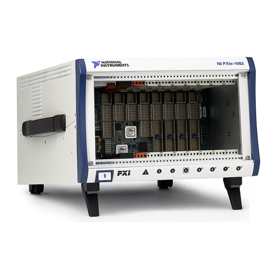
Page 2: Ni Pxie-1082 Backplane Overview
Hybrid Slot Pinouts ................23 NI PXIe-1082 Backplane Overview This section provides an overview of the backplane features for the NI PXIe-1082 chassis. Figure 1 shows the backplane. Figure 1. 8-Slot NI PXIe-1082 Backplane 8-Slot NI PXIe-1082 Backplane Installation Guide ni.com... -
Page 3: Interoperability With Compactpci
Interoperability with CompactPCI With the NI PXIe-1082, you can use the following devices in a single PXI Express system: • PXI Express-compatible products • CompactPCI Express-compatible 4-Link system controller products • CompactPCI Express-compatible Type-2 peripheral products • Hybrid-compatible PXI peripheral products •... -
Page 4: Hybrid Peripheral Slots
A PXI Express peripheral with a x4 or x1 PCI Express link to the system slot through a PCI Express switch. • A CompactPCI Express Type-2 peripheral with a x4 or x1 PCI Express link to the system slot through a PCI Express switch. 8-Slot NI PXIe-1082 Backplane Installation Guide ni.com... - Page 5 PXIe_SYNC100 timing. Refer to the PXI Express Specification and the PXIe_SYNC_CTRL section for details. PXI_STAR2 PXI_STAR6 PXI_STAR5 PXI_STAR0 PXI_STAR4 PXI_STAR1 PXI_STAR3 Figure 3. PXIe_DSTAR and PXI Star Connectivity Diagram © National Instruments 8-Slot NI PXIe-1082 Backplane Installation Guide...
-
Page 6: Pxi Local Bus
Modules can pass triggers to one another, allowing precisely timed responses to asynchronous external events the system is monitoring or controlling. Figure 4 shows the PXI trigger bus connectivity. PXI Trigger Bus Figure 4. PXI Trigger Bus Connectivity Diagram 8-Slot NI PXIe-1082 Backplane Installation Guide ni.com... -
Page 7: System Reference Clock
System Reference Clock The NI PXIe-1082 chassis supplies PXI_CLK10, PXIe_CLK100, and PXIe_SYNC100 to every peripheral slot with an independent driver for each signal. An independent buffer (having a source impedance matched to the backplane and a skew of less than 500 ps between slots) drives PXI_CLK10 to each peripheral slot. - Page 8 If the 10 MHz clock is present on both the PXI_CLK10_IN pin of the System Timing Slot and connector J36, the signal on the System Timing Slot is selected. Refer to Table 1, which explains how the backplane selects the 10 MHz clocks. 8-Slot NI PXIe-1082 Backplane Installation Guide ni.com...
-
Page 9: Pxie_Sync_Ctrl
PXIe_SYNC100 signal. On the next PXI_CLK10 edge, the PXIe_SYNC100 signal restarts. This allows several chassis to have their PXIe_SYNC100 in phase with each other. Refer to Figure 7 for timing details with this method. © National Instruments 8-Slot NI PXIe-1082 Backplane Installation Guide... -
Page 10: Mechanical Requirements
If you do not want to connect the backplane ground to the chassis, use insulated washers at these mounting holes. Refer to Figure 11 for the mounting hole positions. 8-Slot NI PXIe-1082 Backplane Installation Guide ni.com... -
Page 11: Dimensions
Figure 8. Dimensions Cooling Note National Instruments is not responsible for damage to the backplane if inadequate cooling is used. Airflow should be from the bottom to the top of the PXI modules. You must determine the airflow requirements for your system based on the PXI Hardware Specification. -
Page 12: Handling
PXI equipment. Then touch the antistatic plastic package containing the backplane to a metal part of your PXI chassis before removing the backplane from the packaging. 8-Slot NI PXIe-1082 Backplane Installation Guide ni.com... -
Page 13: Electrical Requirements
5 Hybrid Peripheral Slots (5 to 8) 3 PXI Express Peripheral Slots (2 to 3) 6 Power Button Connector Figure 10. PXI Connectors 1 Connector J36 2 Connector J37 Figure 11. Backplane Power and J36 Connectors © National Instruments 8-Slot NI PXIe-1082 Backplane Installation Guide... -
Page 14: Power
CompactPCI Express specification defines. (The specification also defines uses and addressing.) Improper use of the SMBus could result in system controller malfunctions. There are three SMBus slave devices on the NI PXIe-1082 backplane. The Backplane Descriptor EEPROM is at slave address A4... - Page 15 Ground plane +12V_SENSE +12 V sense only, no power +3.3V_SENSE +3.3 V sense only, no power Ground plane +5V_SENSE +5 V sense only, no power +12V +12 V power plane Ground plane © National Instruments 8-Slot NI PXIe-1082 Backplane Installation Guide...
-
Page 16: Connector J36
You can use signals LED1 and LED2 to drive a bicolor LED in the power switch, but you also can use these signals to carry another digital signal. 8-Slot NI PXIe-1082 Backplane Installation Guide ni.com... -
Page 17: Connectors J2, J3, And J4
CompactPCI (PICMG 2.0 R 3.0) 3U modules. Backplane bare-board material ....UL 94 V-0 Recognized Backplane connectors ......Conforms to IEC 917 and IEC 1076-4-101, and are UL 94 V-0 rated © National Instruments 8-Slot NI PXIe-1082 Backplane Installation Guide... -
Page 18: System Synchronization Clock (Pxi_Clk10, Pxie_Clk100, Pxie_Sync100) Specifications
For other specifications, refer to the PXI-5 PXI Express Hardware Specification. Note External 10 MHz Reference Out (on J36) Accuracy ..........±25 ppm max (guaranteed over the operating temperature range) Maximum jitter ........5 ps RMS phase-jitter (10 Hz to 1 MHz range) 8-Slot NI PXIe-1082 Backplane Installation Guide ni.com... -
Page 19: External Clock Source
Backplane characteristic impedance ..65 Ω ±10% Note For PXI slot to PXI Star mapping, refer to the System Timing Slot section of Chapter 1, Getting Started, in the NI PXIe-1082 User Manual. For other specifications, refer to the PXI-1 Hardware Specification. Note... -
Page 20: Pinouts
For PXI Express slot to PXI_DSTAR mapping, refer to the System Timing Slot Note section of Chapter 1, Getting Started, in the NI PXIe-1082 User Manual. Note For other specifications, the NI PXIe-1082 complies with the PXI-5 PXI Express Hardware Specification. -
Page 21: System Controller Slot Pinouts
4PERp1 4PERn1 4PETp3 4PETn3 4PERp3 4PERn3 Table 6. XP3 Connector Pinout for the System Controller Slot PWR_OK PS_ON# LINKCAP PWRBTN# SMBDAT SMBCLK 4RefClk+ 4RefClk- 2RefClk+ 2RefClk- PERST# 3RefClk+ 3RefClk- 1RefClk+ 1RefClk- © National Instruments 8-Slot NI PXIe-1082 Backplane Installation Guide... -
Page 22: System Timing Slot Pinouts
PXIe_DSTARA9+ PXIe_DSTARA9- PXIe_DSTARB1+ PXIe_DSTARB1- PXI_STAR0 PXI_STAR1 PXIe_DSTARB9+ PXIe_DSTARB9- PXIe_DSTARA1+ PXIe_DSTARA1- PXI_STAR2 PXI_STAR3 PXIe_DSTARC10+ PXIe_DSTARC10- PXIe_DSTARC2+ PXIe_DSTARC2- PXI_STAR4 PXI_STAR5 PXIe_DSTARA10+ PXIe_DSTARA10- PXIe_DSTARB2+ PXIe_DSTARB2- PXI_STAR6 PXIe_DSTARB10+ PXIe_DSTARB10- PXIe_DSTARA2+ PXIe_DSTARA2- PXIe_DSTARC11+ PXIe_DSTARC11- PXIe_DSTARA11+ PXIe_DSTARA11- PXIe_DSTARB11+ PXIe_DSTARB11- 8-Slot NI PXIe-1082 Backplane Installation Guide ni.com... -
Page 23: Hybrid Slot Pinouts
Table 11. P1 Connector Pinout for the Hybrid Slot REQ64# ENUM# 3.3V AD[1] V(I/O) AD[0] ACK64# 3.3V AD[4] AD[3] AD[2] AD[7] 3.3V AD[6] AD[5] 3.3V AD[9] AD[8] M66EN C/BE[0]# AD[12] V(I/O) AD[11] AD[10] 3.3V AD[15] AD[14] AD[13] © National Instruments 8-Slot NI PXIe-1082 Backplane Installation Guide... - Page 24 1RefClk- 1PETp0 1PETn0 1PERp0 1PERn0 1PETp1 1PETn1 1PETp2 1PETn2 1PERp2 1PERn2 1PERp1 1PERn1 1PETp3 1PETn3 1PERp3 1PERn3 1PETp4 1PETn4 1PETp5 1PETn5 1PERp5 1PERn5 1PERp4 1PERn4 1PETp6 1PETn6 1PERp6 1PERn6 1PETp7 1PETn7 1PERp7 1PERn7 8-Slot NI PXIe-1082 Backplane Installation Guide ni.com...
- Page 25 Table 13. XP4 Connector Pinout for the Hybrid Slot 5Vaux SYSEN# WAKE# ALERT# 3.3V 3.3V 3.3V PXI_TRIG3 PXI_TRIG4 PXI_TRIG5 PXI_TRIG6 PXI_TRIG2 ATNLED PXI_STAR PXI_CLK10 PXI_TRIG1 PXI_TRIG0 ATNSW# PXI_TRIG7 PXI_LBL6 PXI_LBR6 © National Instruments 8-Slot NI PXIe-1082 Backplane Installation Guide...
- Page 26 Help»Patents in your software, the patents.txt file on your media, or the National Instruments Patent Notice at ni.com/patents. You can find information about end-user license agreements (EULAs) and third-party legal notices in the readme file for your NI product.
Need help?
Do you have a question about the NI PXIe-1082 and is the answer not in the manual?
Questions and answers