Table of Contents
Advertisement
Quick Links
INSTALLER: Leave this manual with the appliance.
CONSUMER: Retain this manual for future reference.
ͷWARNING:
FIRE OR EXPLOSION HAZARD
Failure to follow safety warnings exactly could
result in serious injury, death, or property
damage.
ͷ Do not store or use gasoline or other flammable
ͷ
vapors and liquids in the vicinity of this or any
other appliance.
ͷ WHAT DO IF YOU SMELL GAS
ͷ
• Do not try to light any appliance.
• Do not touch any electrical switch; do not
use any phone in your building.
• Leave the building immediately.
• Immediately call your gas supplier from a
neighbor's phone. Follow the gas supplier's
instructions.
• If you cannot reach your gas supplier, call
the fire department.
ͷ Installation and service must be performed by
ͷ
a qualified installer, service agency or the gas
supplier.
This appliance may be installed in an aftermarket,
permanently located, manufactured home (USA
only) or mobile home, where not prohibited by
local codes.
This appliance is only for use with the type of gas
indicated on the rating plate. This appliance is
not convertible for use with other gases, unless
a certified kit is used.
English
and
are available through your local dealer.
Visit
our
scan this QR code for our mobile app.
French
installation
website
www.kozyheat.com
Rev. 1 • Report Number 216-S-43-6.5
MODEL #CSK-34 R
DIRECT VENT GAS FIREPLACE INSERT
O-T L
Tested &
Listed By
C
OMNI-Test Laboratories, Inc.
manuals
A barrier designed to reduce the risk of burns from
the hot viewing glass is provided with this appliance
or
and shall be installed for the protection of children
and other at-risk individuals.
CSK-34 R • May 2014
HUSSONG MANUFACTURING CO., INC.
Portland
Oregon USA
US
ͷDANGER
HOT GLASS WILL
CAUSE BURNS.
DO NOT TOUCH GLASS
UNTIL COOLED.
NEVER ALLOW CHILDREN
TO TOUCH GLASS.
Advertisement
Table of Contents

Related Manuals for kozy heat CHASKA-34 ROCK


Summary of Contents for kozy heat CHASKA-34 ROCK
- Page 1 HUSSONG MANUFACTURING CO., INC. MODEL #CSK-34 R INSTALLER: Leave this manual with the appliance. DIRECT VENT GAS FIREPLACE INSERT CONSUMER: Retain this manual for future reference. ͷWARNING: FIRE OR EXPLOSION HAZARD Failure to follow safety warnings exactly could result in serious injury, death, or property damage.
- Page 2 CONGRATULATIONS! We welcome you as a new owner of a Kozy Heat gas fireplace. Kozy Heat products are designed with superior components and materials, and assembled by trained craftsmen who take pride in their work. To ensure you receive a quality product, the burner and valve assembly are 100 percent test-fired, and the complete fireplace is thoroughly inspected before packaging.
-
Page 3: Table Of Contents
5.2 Fireplace Insert Air Duct Removal ..........12 11.0 TROUBLESHOOTING ...............29 5.3 Combustion Air Venting Options ...........12 12.0 MAINTENANCE .................31 5.4 Kozy Heat #816-CL Co-Linear Vent System ........13 12.1 Burner and Pilot System ..............31 5.5 Run Vent Through Existing Chimney ..........14 12.2 Fans ....................31 5.6 Vent System Connection ..............15... -
Page 4: Introduction
1.0 INTRODUCTION 1.1 Appliance Certification 1.2.3 Signage A metal or plastic identification plate shall be permanently This appliance has been tested OMNI-Test Laboratories located mounted to the exterior of the building at a minimum of eight (8) in Portland, Oregon and complies with: feet above grade directly in line with the exhaust vent terminal ANSI Z21.88-2014/CSA 2.33a-2014, “Vented Gas Fireplace •... -
Page 5: Specifications
Shrouds: • Part #CK34-2740, 27” x 40” shroud (1 pc.) • Kozy Heat #816-CL Co-linear vent system • Part #CK34-3044, 30” x 44” shroud (1 pc.) - For use with minimum 6” x 8” I.D. masonry or 7” I.D. Class A metal chimneys;... -
Page 6: Appliance Dimensions And Assembly
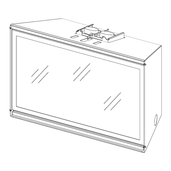
2.4 Appliance Dimensions and Assembly Table 2.2, Physical Dimensions Back to Gas Front to Vent Back to Vent Description Height Width Back Width Depth Back Height Line Access Center Center 9/16 Inches 33⅜ 24⅜ 17⅜ 10⅜ 5⅝ Millimeters Figure 2.1, CSK-34 Dimensions Table 2.3, Part Assembly Overview Fireplace insert Rock kit... -
Page 7: Safety Barriers Dimensions
2.5 Safety Barriers Dimensions • A safety barrier designed to reduce the risk of burns from the hot viewing glass is provided with this appliance and shall be installed for the protection of children and other at-risk individuals. • If the safety barrier becomes damaged, the barrier shall CK34-RSF be replaced only with Hussong Mfg. -
Page 8: Existing Fireplace Requirements
3.0 EXISTING FIREPLACE REQUIREMENTS 3.1 Existing Fireplace Specifications 3.2 Existing Chimney Specifications NOTE: This fireplace is approved for installation in masonry WARNING: Any chimney clean-outs must fit properly. This and factory-built solid fuel burning fireplaces. appliance must not share, or be connected, to a chimney flue serving any other appliance. -
Page 9: Clearances
4.0 CLEARANCES 4.1 Fireplace Insert Placement 4.3.2 Projection Requirements Considerations 7 in. (178 mm) of non-combustible flooring in front of the appliance is required if this appliance is directly installed on the • This fireplace must be installed on a level surface capable of fireplace floor. -
Page 10: Installation
5.0 INSTALLATION 5.1 Prepare Existing Fireplace 5.3 Combustion Air Venting Options CAUTION: Trim panels or surrounds must not seal ventilation WARNING: The flow of combustion and ventilation air must not openings in existing fireplace that this appliance is installed in. be obstructed. -
Page 11: Kozy Heat #816-Cl Co-Linear Vent System
5.4 Kozy Heat #816-CL Co-Linear Vent 5.4.2 Stub Venting Assembly System Determine the length needed for the combustion air intake pipe, measuring from the fireplace air duct to above to a IMPORTANT: Proper operation of this insert requires the minimum length of 4 ft. (1.22 m) above the damper opening exhaust and combustion air pipes to be connected to the in the existing chimney. -
Page 12: Run Vent Through Existing Chimney
5.5 Run Vent Through Existing 5.5.2 Run Vent - Stub Venting Chimney Guide the rope (if used) and the exhaust pipe down the existing chimney. See Figure 5.3, Chimney Vent Run. NOTE: If offsets are present in existing chimney, place a Secure the chimney termination cap to the existing chimney. -
Page 13: Vent System Connection
5.6 Vent System Connection (applies 5.6.2 Secure Air Duct to Fireplace Insert to both venting options) Insert air duct pull handle (included) through the access slot the at top of insert, placing hook through hole in pull rod. 5.6.1 Secure Vent System to Air Duct Simultaneously pull the air duct forward and push the insert backward into the fireplace opening until the air duct is Place previously removed air duct (5.2 Fireplace Insert Air... -
Page 14: Gas Line Connection
6.0 GAS LINE CONNECTION 6.1 Gas Conversion (sold separately) ATTENTION: The conversion shall be carried out in accordance with the requirements of the provincial authorities having jurisdiction and in accordance with the requirements of the ANSI Z223.1 installation code. This fireplace is manufactured for use with natural gas. Follow the instructions included with the conversion kit if converting to LP gas. -
Page 15: Fireplace Insert Setup
7.0 FIREPLACE INSERT SETUP 7.1 Glass Assembly WARNING: Do not operate this fireplace with the glass removed, cracked, or broken. Replacement of the glass assembly #701-001T, should be done by a licensed or qualified service person. 7.1.1 Remove Glass Assembly WARNING: Do not remove the glass assembly when hot. -
Page 16: Ck34-R500 Rock Kit Installation
7.2 #CK34-R500 Rock Kit Installation Reinstall the burner tube. Verify gasket is underneath. Place the (8) spacers onto the pins on the burner. Tighten CAUTION: Do not place rocks directly over burner port holes. 5/16 with the nuts included with this kit using a ”... -
Page 17: Control Board Removal And Installation
7.3 Control Board Removal and Installation WARNING: If burner and/or pilot have been burning, use appropriate protection to avoid burns or damage to personal property before removing any components. CAUTION: Check all connections for leaks with soapy water, whether field or factory made. 7.3.1 Control Board Removal Turn the fireplace off. -
Page 18: Electrical Information
8.0 ELECTRICAL INFORMATION 8.2 Wiring Requirements WARNING: Do not use this fireplace if any part has been under water. Immediately call a qualified service technician to inspect • The IFC System Module requires 120V of electricity / this appliance and to replace any part of the control system and any gas control which has been under water. -
Page 19: Ck34-Lkt Optional Light Kit Installation
8.3 CK34-LKT Optional Light Kit Installation ATTENTION: If converting to LP (propane) gas, complete the conversion before installing this light kit. Follow instructions included with the gas conversion kit. CAUTION: Disconnect all electric power from the fireplace insert before performing any of these tasks. First Access Cover NOTE: To avoid damage and prolong the life of the halogen bulbs, never touch with bare hands. -
Page 20: Operating Instructions
9.0 OPERATING INSTRUCTIONS FOR YOUR SAFETY READ BEFORE OPERATING WARNING: If you do not follow these instructions exactly, a fire or explosion may result causing property damage, personal injury or loss of life. This appliance is equipped with an ignition device which in your building. -
Page 21: Initialize The Control System For The First Time
9.1 Initialize the Control System for Press the red SW1 button on the IFC module. The control module will BEEP (3) times, and/or illuminate the First Time an amber LED, indicating it is ready to synchronize with the Remove all packaging and combustible material from the remote control. -
Page 22: Temperature Display
9.2 Temperature Display With the system in OFF position, press thermostat key and mode key at the same time to change from degrees °F to degrees °C. Look at the LCD screen on the remote control to verify °C or °F is visible on the right side of the Room Temperature display. -
Page 23: Continuous Pilot / Intermittent Pilot (Ipi/Cpi) Selection
9.8 Fan Speed Control 9.6.3 Deactivate Remote Control Thermostat Operation Fan speed can be adjusted through six (6) speeds. A single The thermostat operation function on the remote control can be ‘beep’ will confirm reception of the command. To activate this deactivated. -
Page 24: Reset The System For Manual Operation
9.10.2 Backup Battery Pack • After this wait time, the IFC module will start the second try for ignition by sparking for approximately (60) seconds. The backup battery pack is used when electrical power to • If ignition is successful on third ignition attempt, there will be the appliance is interrupted. -
Page 25: Adjustment
10.0 ADJUSTMENT 10.1 Pressure Testing 10.1.2 Manifold Pressure Test Light pilot. NOTE: The appliance and its appliance main gas valve must be disconnected from the gas supply piping system during any Loosen manifold (OUT) pressure tap by turning screw pressure testing of the system at test pressures in excess of ½ counter-clockwise. -
Page 26: Burner Tube Venturi Adjustment
10.2 Burner Tube Venturi Adjustment 10.2.3 Flame Appearance and Adjustment IMPORTANT: Slight adjustments to the venturi opening will 10.2.1 Flame Appearance create dramatic results. Adjust at slight increments until desired look is achieved. Always burn the fireplace for at least Flame appearance is affected by several factors;... -
Page 27: Troubleshooting
11.0 TROUBLESHOOTING ATTENTION: Troubleshooting must be performed by a qualified system components are proper and positive. technician. • Verify the communication link is established between the Before proceeding with the steps in the following troubleshooting remote control and the IFC module. guide, •... - Page 28 Issue Cause Solution Pilot and burner No LP gas in tank Check LP (propane) tank. Refill if necessary. extinguish while in operation Incorrect glass assembly Refer to 7.1 Glass Assembly, on page 17. installation Incorrect vent cap installation Adjust if necessary Vent cap blockage Remove debris if necessary Inner vent pipe leaking exhaust...
-
Page 29: Maintenance
12.0 MAINTENANCE 12.3 Vent System ATTENTION: Installation and repair shall only be done by a qualified service person. The appliance should be inspected NOTE: If the vent-air intake system is disassembled for any before use by a qualified service person. This appliance is reason, reinstall per instructions provided with installation. -
Page 30: Replacement Parts List
13.0 REPLACEMENT PARTS LIST Replacement parts are available through your local dealer. Contact your local dear for availability and pricing. CONTROL BOARD AND PARTS Control Board - NG CK34L-150 Pilot Orifice - LPG 700-168 Control Board - LPG CK34L-151 Valve Step Motor - NG 700-504 S.I.T. -
Page 31: Limited Warranty
Hussong Manufacturing Co., Inc. warranties to the original void. purchaser of this Kozy Heat Fireplace, that it is free of defects in This limited warranty also is void if the fireplace is not operated, materials and workmanship at the time of manufacture. -
Page 33: Lifetime Warranty
The foregoing and glass panel of this Kozy Heat Fireplace will not be defective warranty is exclusive and in lieu of all other expressed warranties.