Table of Contents
Advertisement
Quick Links
HUSSONG MANUFACTURING CO., INC.
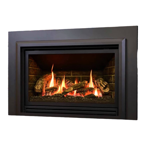
CHASKA-335S
Model #CSK-335S
Direct Vent Gas Fireplace Insert
WARNING:
FIRE OR EXPLOSION HAZARD
Failure to follow safety warnings exactly
could result in serious injury, death, or
property damage.
ͷ Do not store or use gasoline or other
flammable vapors and liquids in the
vicinity of this or any other appliance.
ͷ WHAT TO DO IF YOU SMELL GAS
• Do not try to light any appliance.
• Do not touch any electrical switch; do
not use any phone in your building.
• Leave the building immediately.
• Immediately call your gas supplier from
a neighbor's phone. Follow the gas
supplier's instructions.
• If you cannot reach your gas supplier,
call the fire department.
ͷ Installation and service must be performed
by a qualified installer, service agency or
the gas supplier.
This
appliance
an
aftermarket,
manufactured home (USA only) or mobile
home, where not prohibited by local codes.
This appliance is only for use with the type
of gas indicated on the rating plate. This
appliance is not convertible for use with
other gases, unless a certified kit is used.
Hussong Mfg. Co., Inc. • CSK-335S
may
be
installed
permanently
located,
INSTALLER: Leave this manual with the appliance.
CONSUMER: Retain this manual for future reference.
O-T L
Tested &
Listed By
C
OMNI-Test Laboratories, Inc.
DANGER
A barrier designed to reduce the risk of burns
from the hot viewing glass is provided with this
appliance and shall be installed for the protection
of children and other at-risk individuals.
in
English
and
available through your local dealer. Visit our website
www.kozyheat.com or scan the QR code for our mobile app.
Les manuels d'installation en français et en anglais sont
disponibles chez votre détaillant local. Visitez www.kozyheat.
com ou scannez ce code QR pour notre application mobile.
Report No.: 0216GN012S • Rev. 04, August 2015
Installation and
Operation Manual
Portland
Oregon USA
US
HOT GLASS WILL
CAUSE BURNS
DO NOT TOUCH GLASS
UNTIL COOLED
NEVER ALLOW CHILDREN
TO TOUCH GLASS
French
installation
manuals
are
Advertisement
Table of Contents

Related Manuals for kozy heat CHASKA-335S


Summary of Contents for kozy heat CHASKA-335S
- Page 1 Installation and Operation Manual HUSSONG MANUFACTURING CO., INC. CHASKA-335S Model #CSK-335S Direct Vent Gas Fireplace Insert WARNING: O-T L Tested & Portland FIRE OR EXPLOSION HAZARD Listed By Oregon USA Failure to follow safety warnings exactly OMNI-Test Laboratories, Inc. could result in serious injury, death, or property damage.
- Page 3 Please retain this owner’s manual for future reference. CONGRATULATIONS! We welcome you as a new owner of a Kozy Heat gas fireplace. Kozy Heat products are designed with superior components and materials; assembled by trained craftsmen who take pride in their work. The burner and valve assembly are 100% test-fired, and the complete fireplace is thoroughly inspected before packaging to ensure you receive a quality product.
-
Page 5: Table Of Contents
REPLACEMENT PARTS LIST Electrical Wiring LIMITED WARRANTY Fireplace Conversion LIFETIME WARRANTY CLEARANCES INSTALLATION Kozy Heat #816-CL Co-Linear Vent System Fireplace Air Duct Removal Run Vent System Through Existing Chimney Vent System Connection GAS LINE CONNECTION Gas Conversion Gas Line Installation... -
Page 6: Introduction
INTRODUCTION Appliance Certification This appliance has been tested by OMNI-Test Laboratories located in Portland, Oregon and complies with: ANSI Z21.88a-2012/CSA 2.33a-2012, “Vented Gas Fireplace Heaters” CGA 2.17-M91 (R2009), “Gas-Fired Appliances for Use at High Altitudes” CSA P.4.1-2009, “Testing Method for Measuring Annual Fireplace Efficiency” ... -
Page 7: Specifications
Approved Venting Systems: Part #CK34-2740, 27” x 40” Shroud (1 pc) Kozy Heat #816-CL Co-Linear Direct Vent System Part #CK34-3044, 30” x 44” Shroud (1 pc) For use with minimum 6” x 8” I.D. masonry or 7” I.D. -
Page 8: Appliance Dimensions And Assembly
Appliance Dimensions and Assembly Table 2.4, Physical Dimensions Back to Electrical Back to Gas Line Front to Vent Back to Vent Description Height Width Back Width Depth Back Height Access Access Center Center Inches 33-3/8 24-3/8 17-1/4 9-1/2 5-1/8 1038 Millimeters Figure 2.1, CSK-335S Dimensions "... -
Page 9: Safety Barriers
Safety Barriers WARNING A barrier designed to reduce the risk of burns from the hot viewing glass is provided with this appliance and shall be installed for the protection of children and other at-risk individuals. If the safety barrier becomes damaged, the barrier shall be replaced only with Hussong Mfg. Co., Inc.’s barrier for this appliance. -
Page 10: Existing Fireplace Requirements
EXISTING FIREPLACE REQUIREMENTS Appliance Placement Considerations WARNING Due to high surface temperatures, the fireplace insert should be located out of traffic and away from furniture and draperies. This fireplace must be installed on a level surface capable of supporting the fireplace insert and venting. ... -
Page 11: Termination Location
TERMINATION LOCATION Vent Termination Clearances WARNING This appliance must not share or be connected to a chimney flue serving a separate solid-fuel burning appliance. Approved vent caps require 12 in (305mm) clearance to intersecting walls, overhangs, or eaves as verified by test. -
Page 12: Installation Preparation
INSTALLATION PREPARATION NOTE This gas fireplace insert is approved for installation in masonry and factory-built solid fuel burning fireplaces. ATTENTION Any removed parts must be capable of reinstallation if this insert is ever removed. Removal of rivets or screws is acceptable. Inspect and Clean Existing Chimney ... -
Page 13: Clearances
CLEARANCES CAUTION Trim panels or surrounds must not seal ventilation openings in existing fireplace that this appliance is installed in. Table 6.1, Appliance Clearances to Combustible Material Fireplace insert to sidewall 12 in. 305 mm Fireplace insert bottom to combustible floor in front of appliance 6 in. -
Page 14: Installation
INSTALLATION Kozy Heat #816-CL Co-Linear Vent System IMPORTANT Proper operation of this insert requires exhaust and combustion air pipes be connected to the correct collars on both the termination kit and the fireplace insert air duct. NOTE Maximum horizontal vent runs of 24 in (609mm) require a 1 in (25mm) rise per 12 in (305mm) run. -
Page 15: Fireplace Air Duct Removal
Kozy Heat #816-CL: Secure termination cap to existing chimney with 2 in. (50 mm) self tapping screws and anchor straps (provided) through the pilot holes, located on the sides of the termination cap. -
Page 16: Vent System Connection
Vent System Connection 7.4.1 Secure Vent System to Air Duct 1. Place previously removed air duct (7.2, Air Duct Removal, page 12) into existing fireplace opening. See Figure 7.4a, Air Duct in Existing Fireplace. 2. Apply a bead of sealant (provided) around exhaust pipe (red marking), then slide the exhaust pipe inside collar marked ‘Exhaust’... -
Page 17: Gas Line Connection
GAS LINE CONNECTION Gas Conversion (sold separately) This fireplace is manufactured for use with Natural Gas. Follow the instructions included with the conversion kit if converting to LP gas. ATTENTION The conversion shall be carried out in accordance with the requirements of the provincial authorities having jurisdiction and in accordance with the requirements of the ANSI Z223.1 installation code. -
Page 18: Fireplace Insert Setup
FIREPLACE INSERT SETUP Glass Frame Assembly WARNING Do not operate this fireplace with the glass removed, cracked, or broken. Replacement of the glass frame assembly, #700-006T, should be done by a licensed or qualified service person. Do not remove the glass frame assembly when hot. 9.1.1 Remove Glass Frame Assembly Figure 9.1, Glass Frame Assembly Removal and Installation... -
Page 19: Csk-028 Fan Kit Installation
#CSK-028 Optional Fan Kit WARNING Electrical Grounding Instructions: This appliance is equipped with a three-prong (grounding) plug for your protection against shock hazard and should be plugged directly into a properly grounded three-prong receptacle. Do not cut or remove the grounding prong from this plug. -
Page 20: Cxl2-500 Log Set
CXL2-500 Log Set CAUTION Do not place the logs directly over the burner port holes. Improper log placement may affect flame appearance and cause excessive soot to build up on the glass. Align the holes on the bottom of logs 3CX and 4CX with the ... -
Page 21: Control Board Removal And Installation
Control Board Removal and Installation CAUTION If burner and/or pilot have been burning, use appropriate protection to avoid burns or damage to personal property before removing any components. Check all connections for leaks with soapy water, whether field or factory made. 9.4.1 Control Board Removal Turn the fireplace off. -
Page 22: Thermostat, Wall Switch, Remote Control
10.0 THERMOSTAT, WALL SWITCH, REMOTE If desired, a thermostat, a wall switch, or a remote control assembly may be installed to enable on/off control of the main burner. Only one of these components may be installed. Follow instructions included with the component. CAUTION Do not connect high voltage (115V) wire to the gas valve. -
Page 23: Lighting Instructions
11.0 LIGHTING INSTRUCTIONS FOR YOUR SAFETY READ BEFORE OPERATING WARNING: If you do not follow these instructions exactly, a fire or explosion may result causing property damage, personal injury or loss of life. This appliance has a pilot which must be lighted by hand. If you cannot reach your gas supplier, call the fire department. -
Page 24: Adjustment
12.0 ADJUSTMENT 12.1 Pressure Testing NOTE The appliance and its appliance main gas valve must be disconnected from the gas supply piping system during any pressure testing of the system at test pressures in excess of 1/2 psi (3.5 kPa). IMPORTANT Pressure check taps for manifold (outgoing) and inlet (incoming) pressure have been incorporated into the valve. -
Page 25: Burner Tube Venturi Adjustment
12.2 Burner Tube Venturi Adjustment 12.2.1 Flame Appearance Figure 12.2, Correct Burner and Pilot Flame Appearance Flame appearance is affected by several factors; including altitude, venting configuration, and fuel quality. Although the Lazy yellow flames venturi setting has been factory set, adjustments may be necessary for optimal performance and visual aesthetics. -
Page 26: Troubleshooting
13.0 TROUBLESHOOTING ATTENTION TROUBLESHOOTING MUST BE PERFORMED BY A QUALIFIED TECHNICIAN. Issue Cause Solution Check and repair, if necessary, wire connections between piezo Piezo igniter wiring No spark from electrode disconnection igniter and igniter electrode. to pilot when piezo button is triggered Verify piezo igniter is properly grounded. - Page 27 Issue Cause Solution Turn gas control knob to ON position. Lighting instructions not Burner will not light followed Turn the ON/OFF rocker switch to ON position. Put wall switch, remote control, or thermostat in heat demand Remove blockage as necessary. Plugged main burner orifice Check remote, thermostat, or wall switch wires for proper Switching device is defective...
-
Page 28: Maintenance
14.0 MAINTENANCE ATTENTION Installation and repair should be done by a qualified service person. The appliance should be inspected before use and at least annually by a professional service person. More frequent cleaning might be required due to excessive lint from carpeting, bedding material, et cetera. -
Page 29: Glass Frame Assembly
14.4 Glass Frame Assembly CAUTION Do not operate appliance with the glass frame assembly removed, cracked, or broken. Use protective gloves to handle any broken or damaged glass assembly components. WARNING Do not substitute materials. WARNING Avoid striking or slamming glass frame assembly. Avoid abrasive cleaner. DO NOT clean glass while it is hot. IMPORTANT Any safety screen, guard, or barrier removed for servicing the appliance must be replaced prior to operating the appliance. -
Page 30: Replacement Parts List
15.0 REPLACEMENT PARTS LIST Replacement parts are available through your local dealer. Contact your dealer for availability and pricing. CONTROL BOARD AND PARTS CXL-770A Natural Gas Millivolt Control Board 700-094 Natural Gas Pilot Orifice CXL-771A LP Gas Millivolt Control Board 700-095 LP Gas Pilot Orifice 700-023... -
Page 31: Limited Warranty
Hussong Manufacturing Co., Inc. warranties to the original purchaser of this Kozy Heat Fireplace, that it is free of defects in materials and workmanship at the time of manufacture. -
Page 33: Lifetime Warranty
Co., Inc. warranties to the original purchaser that the firebox, heat exchanger, fiber logs, burner tube and glass panel of this Kozy Heat Fireplace will not be defective in material or workmanship under normal use and service for as long as you own this product. If any of these components fail due to defects in material and workmanship under normal use and service, Hussong Manufacturing, Co., Inc.
Need help?
Do you have a question about the CHASKA-335S and is the answer not in the manual?
Questions and answers