Advertisement
Quick Links
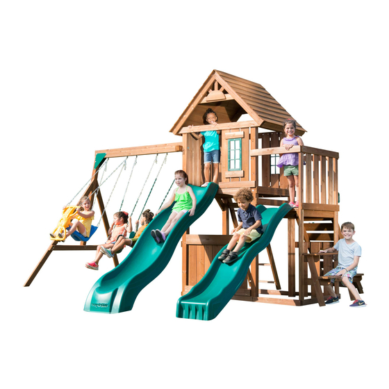
WS 8353
IMPORTANT!!
PLEASE READ BEFORE BEGINNING ASSEMBLY!!
Please make sure all lumber, hardware and accessory parts are accounted for.
If you are missing anything, please DO NOT RETURN to the store where purchased.
Please call our Customer Service Department at the number below.
ASSEMBLY INSTRUCTIONS
Swing•N•Slide • 1212 Barberry Drive • Janesville, Wisconsin 53545
Visit our web site at: www.swing-n-slide.com or call us at 1-800-888-1232
LDR 1-17-2018
© Swing-N-Slide Inc.
Printed in USA
LA 9372
Advertisement

Related Manuals for Swing-N-Slide WS 8353


Summary of Contents for Swing-N-Slide WS 8353
- Page 1 Please call our Customer Service Department at the number below. ASSEMBLY INSTRUCTIONS Swing•N•Slide • 1212 Barberry Drive • Janesville, Wisconsin 53545 Visit our web site at: www.swing-n-slide.com or call us at 1-800-888-1232 LDR 1-17-2018 © Swing-N-Slide Inc. Printed in USA...
- Page 2 Safety Checklist for Swing-N-Slide Play Sets and Accessories Observing the following statesments and warnings reduces the likelihood of serious or fatal injury This playset has been designed for use by a maximum of thirteen (13) occupants at one time having a combined weight of 1,365 pounds. This playset is intended for use by children from (2) to (10) years of age. On-site adult supervision for children of all ages is recommended. Instruct children not to walk close to, in front of, behind, or between moving items. Instruct children not to twist swing chains or ropes or loop them over the top support bar since this may reduce the strength of the chain or rope. Instruct children to avoid swinging empty seats. Teach children to sit in the center of the swings with their full weight on the seats. Instruct children not to use the equipment in a manner other than intended.
- Page 3 PLAYSET MAINTENANCE Cosmetic defects that do not affect the structural integrity of the product, or natural defects of wood such as warping, splitting, checking, twisting, shrinkage, swelling or any other physical properties of wood that do not present a safety hazard, are not covered by our warranty. To help minimize these natural defects we recommend applying a sealer or stain every two or three years, or more often as the climate dictates. Power washing, sanding or other preparatory methods should be used prior to sealing or staining. Periodic maintenance is required to ensure safe enjoyment of your playset and accessories. Read and follow the Playset Checklist below to reduce the likelihood of serious or fatal injury. Use the checklists as a guide for proper playset care and maintenance. PLAYSET CHECKLIST At the beginning of each play season: Tighten all hardware. Lubricate all metallic moving parts per manufacturer's instructions. Check all protective coverings on bolts, pipes, edges, and corners. Replace if they are loose, cracked, or missing. Check all moving parts including swing seats, ropes, cables, and chains for wear, rust, or other deterioration. Replace as needed. Check metal parts for rust. If found, sand and repaint using a nonleaded-based paint meeting the requirements of 16 CFR 1303. Check all wood members for deterioration and splinters. Sand down splinters and replace deteriorating wood members. Reinstall any plastic parts, such as swing seats or any other items that were removed for the cold season. Rake and check depth of loose fill protective surfacing materials to prevent compaction and to maintain appropriate depth. Replace as necessary. Twice a month during play season: Tighten all hardware. Check all protective coverings on bolts, pipes, edges, and corners. Replace if they are loose, cracked, or missing. Rake and check depth of loose fill protective surfacing materials to prevent compaction and to maintain appropriate depth. Replace as necessary. Once a month during play season: Lubricate all metallic moving parts per manufacturer's instructions.
- Page 4 PLAYGROUND SURFACING MATERIALS SECTION 4 OF THE CONSUMER PRODUCT SAFETY COMMISSION'S OUTDOOR HOME PLAYGROUND SAFETY HANDBOOK Select Protective Surfacing One of the most important things you can do to reduce the likelihood of serious head injuries is to install shock-absorbing protective surfacing under and around your play equipment. The protective surfacing should be applied to a depth that is suitable for the equipment height in accordance with ASTM Specification F 1292. There are different types of surfacing to choose from; whichever product you select, follow these guidelines: NOTE: Do not install home playground equipment over concrete, asphalt, or any other hard surface. A fall onto a hard surface can result in serious injury to the equipment user. Grass and dirt are not considered protective surfacing because wear and environmental factors can reduce their shock absorbing effectiveness. Carpeting and thin mats are generally not adequate protective surfacing. Ground level equipment - such as a sandbox, activity wall, playhouse or other equipment that has no elevated play surface - does not need any protective surfacing. Maximum fall height for this playset is 85''. Loose-Fill Materials: Maintain a minimum depth of 9 inches of loose- fill materials such as wood mulch/chips, engineered wood fiber (EWF), or shredded/recycled rubber mulch for equipment up to 8 feet high; and 9 inches of sand or pea gravel for equipment up to 5 feet high. NOTE: An initial fill level of 12 inches will compress to about a 9- inch depth of surfacing over time. The surfacing will also compact, displace, and settle, and should be periodically refilled to maintain at least a 9- inch depth.
- Page 5 PLAYEST SAFETY ZONE 6'-0" 14'-0" 16'-2 9/16" 6'-0" 6'-0" 28'-0" 28'-8" 13'-8 1/16" 14'-0" 6'-0" 6'-0" 28'-2 3/16" MINIMUM USE ZONE FOR PLAY EQUIPMENT SHALL EXTEND NO LESS THAN 72” FROM ALL SIDES OF THE PLAY STRUCTURE. SWING USE ZONE EXTENDS NO LESS THAN 168”. SWINGS MUST HAVE A MINIMUM CLEARANCE OF 8”...
-
Page 6: Tools Required
REMEMBER- If you are missing anything, please DO NOT RETURN to the store where purchased. Contact our Customer Service Department at 1-800-888-1232 or email us at: service@swing-n-slide.com For ease in inventorying your wooden playset parts all have been marked with a part number. Look for the part number typically located on the end of the part. -
Page 7: Board List
(1) [PF 6035] 1-3/8’’ x 3-3/8’’ x 66-1/4’’ LADDER SUPPORT-R ASSEMBLY INSTRUCTIONS TERRACE MODULE: SA6001 Swing•N•Slide • 1212 Barberry Drive • Janesville, Wisconsin 53545 Visit our web site at: www.swing-n-slide.com or call us at 1-800-888-1232 (2) [PF 6002] 3/4’’ x 3-3/8’’ x 22-1/2’’ © Swing-N-Slide Inc. Printed in USA... - Page 8 TOWER MODULE SA6051 / SA6022 COMPONENTS CONT. Play Handle (x2) Alpine Slide (x1) Cool Wave Slide (x1) STD Swing Seat (x2) Wind Rider Handle (x1) Wind Rider Seat (x1) Quick Link (x8) 58” Dipped Chain (x4) 51” Chain (x4) Beam Clamp Slotted (x6) Climbing Rock (x6) (x1) Star Bit...
- Page 9 TOWER MODULE SA6051 / SA6022 HARDWARE 1/4’’ Washer (x16) 5/16” Washer (x24) 5/16’’ Loc Washer (x12) 5/16” Loc Nut (x9) 1/4’’ Loc Washer (x12) #12 x 3/4” Truss Screw (x14) 5/16” Wood Loc 1/4’’ x 1-3/4” Pan Screw (x4) Washer (x3) FS2831 FS2831 FS2831...
- Page 10 /16’’ x 3’’ x 62’’ A-FRAME SUPPORT (2) [PF 6060] 5/8’’ x 5-3/8’’ x 13’’ SUN TERRACE MODULE SA6001 ’’ x 3-3/8’’ x 83’’ A-FRAME LEGS BOARD LIST (4) [PF 6001] 5/8’’ x 5-3/8’’ x 9-1/4’’ TERRACE MODULE: SA6001 ’’ x 3-3/8’’ x 60’’ ROCKWALL SUPPORT (1) [PF 6061] 1-1/2’’...
- Page 11 (5) [PF 6005] 3/4’’ x 3-3/8’’ x 42’’ (1) [PF 6034] 1-3/8’’ x 3-3/8’’ x 66-1/4’’ LADDER SUPPORT-L (1) [PF 6022] 3/4’’ x 3-3/8’’ x 19-1/2’’ (2) [PF 6003] 3/4’’ x 3-3/8’’ x 35-7/8’’ (1) [PF 6035] 1-3/8’’ x 3-3/8’’ x 66-1/4’’ LADDER SUPPORT-R LADDER MODULE SA6005 (2) [PF 6002] 3/4’’...
- Page 12 FORT ENCLOSURE WOOD ROOF BOARD LIST BOARD LIST (7) [PF 6407] 5/8’’ x 5-3/8’’ x 29-5/8’’ (1) [PF 6408] 3/4’’ x 5-3/8’’ x 41-1/2’’ FS2831 (18) [PF 6055] 1/2’’ x 5’’ x 47-1/2’’ SHINGLE (1) [PF 6410] 3/4’’ x 5-3/8’’ x 41-1/2’’ ARCHED (2) [PF 6061] 1-1/2’’...
- Page 13 STEP 1 6’’ 47-1/2’’ 2-1/2’’ Screws Flush 6’’ 2-1/2’’ Screws T-Nut Small 2-1/2’’ Screws 5/16-18 X 4’’ Hex Head Bolt 5/16’’ Washer 5/16’’Loc-Washer 59-1/4’’ 57-9/16’’ FRAME A 2-1/2’’ Screws 1-1/2’’ Hint!! Use parts from your Tower Box. BOTH SIDES 2-1/2” Deck Screw (x14) 1.
- Page 14 STEP 2 6’’ 47-1/2’’ 2-1/2’’ Screws Flush 6’’ 2-1/2’’ Screws T-Nut Small 2-1/2’’ Screws 5/16-18 X 4’’ Hex Head Bolt 5/16’’ Washer 5/16’’Loc-Washer 2-1/2’’ Screws 57-9/16’’ 2-1/2’’ Screws 59-1/4’’ 31’’ FRAME B 2-1/2’’ Screws 1-1/2’’ JOINTS 2-1/2” Deck Screw (x18) 1.
- Page 15 STEP 3 Check to make sure struc- 2-1/2’’ Screws 2-1/2’’ Screws ture is square Flush 2-1/2’’ Screws 59-1/4’’ Flush 2-1/2’’ Screws 2-1/2’’ Screws FRAME A 2-1/2” Deck Screw (x11) 1. Attach support boards to Frame A as shown.
- Page 16 STEP 4 2-1/2’’ Screws Check to make sure struc- ture is square 2-1/2’’ Screws 2-1/2’’ Screws FRAME B FRAME A 2-1/2’’ Screws 2-1/2” Deck Screw (x11) 1. Attach Frame A to Frame B as shown.
- Page 17 STEP 5 2-1/2’’ Screws PF 6149 1-3/8’’ x 3-3/8’’ x 15-1/2’’ DECK SUPPORT Flush Flush 1-3/4’’ Screw per joint (4) 3’’ Screw 1-3/4” Deck Screw (x6) 3” Deck Screw (x4) 1. Install Deck Supports as shown.
-
Page 18: Top View
STEP 6 PF 6003 3/4’’ x 3-3/8’’ x 35-7/8’’ 1-3/4’’ Screws 1-3/4’’ Screws PF 6003 3/4’’ x 3-3/8’’ x 35-7/8’’ 2-1/2’’ Screws PF 6011 1’’ x 3/8’’ x 47-1/2’’ 16-1/2’’ FS2831 PF 6011 1’’ x 3/8’’ x 47-1/2’’ FS2830 2-1/2 16-1/2’’... - Page 19 STEP 7 PF 6008 3/4’’ x 5-3/8’’ x 42’’ 1-3/4’’ Screws per deck board All Boards Flush With 3’’ x 3’’s 1-3/4” Deck Screw (x42) 1. Install Deck Boards as shown. NOTE: Standard gap between deck boards is 3/8’’.
- Page 20 STEP 8 Flush PF 6002 3/4’’ x 3-3/8’’ x 22-1/2’’ Flush With 2-1/2’’ Screws 3’’ x 3’’s PF 6002 3/4’’ x 3-3/8’’ x 22-1/2’’ 2-1/2’’ Screws 2-1/2’’ Screws Flush With (2) PF 6005 3/4’’ x 3-3/8’’ x 42’’ Bottom of 62-5/8’’...
- Page 21 STEP 9 Check to make sure struc- ture is square 47-1/4’’ 2-1/2’’ Screws FRAME A 5/16-18 X 4’’ Hex Head Bolt 5/16’’Loc-Washer 5/16’’ Washer Hint!! Use parts from your Terrace Box. T-Nut Small 2-1/2” Deck Screw (x4) 1. Install Deck Support Board as shown.
- Page 22 STEP 10 Check to make sure struc- ture is square 2’’ Screws COUNTERBORE THIS SIDE Flush 2’’ Screws COUNTERBORE THIS SIDE 45-9/16’’ 2’’ Screws Flush FS2831 2’’ Screws FRAME C FS2830 2-1/2 FS2829 2” Deck Screw (x12) FS2828 1. Assemble Frame C as shown. 1-3/4 FS2827 1-5/8...
- Page 23 STEP 11 Check to make sure struc- ture is square 5/16-18 X 2’’ 47-1/4’’ Hex Head Bolt 5/16’’Loc-Washer 5/16’’ Washer 2’’ Screws T-Nut Small 2” Deck Screw (x4) 1. Install Deck Support Board as shown.
- Page 24 STEP 12 Flush With Outside Face of 1-3/8’’ x 3’’ 2-1/2’’ Screws Check to make sure struc- ture is square Flush With Flush With Outside Top of Flush With Face of Frame Top of 1-3/8’’ x 3’’ Frame 2-1/2’’ Screws Flush With Outside Face of...
- Page 25 STEP 13 Check to make sure struc- ture is square 2-1/2’’ Screws 79’’ 2-1/2’’ Screws 2-1/2’’ Screws 2-1/2’’ Screws FRAME C 2-1/2” Deck Screw (x10) 1. Attach Frame C to Tower as shown.
- Page 26 STEP 14 1-3/4’’ Screws 1-3/4’’ Screws PF 6150 3/4’’ x 3-3/8’’ x 24-3/4’’ PF 6150 3/4’’ x 3-3/8’’ x 24-3/4’’ 1-3/4’’ Screws 1-3/4’’ Screws PF 6150 3/4’’ x 3-3/8’’ x 24-3/4’’ 1-3/4’’ Screws PF 6061 1-1/2’’ x 1-1/2’’ x 40’’ 1-3/4’’...
- Page 27 STEP 15 All Boards PF 6135 3/4’’ x 5-3/8’’ x 26-1/4’’ Flush 1-3/4’’ Screws per board Note: Holes 1-7/8’’ From Edge on This Side 1-3/4” Deck Screw (x36) 1. Install Deck Boards as shown. NOTE: Standard gap between deck boards is 7/16’’.
- Page 28 STEP 16 PF 6023 3/4’’ x 3-3/8’’ x 22-1/2’’ 2’’ Screws PF 6022 3/4’’ x 3-3/8’’ x 19-1/2’’ 2’’ Screws 50-5/8’’ 2” Deck Screw (x6) 1. Install Barrier Support Boards as shown.
- Page 29 STEP 17 PF 6004 3/4’’ x 3-3/8’’ x 42’’ 2-1/2’’ Screws PF 6005 3/4’’ x 3-3/8’’ x 42’’ 2-1/2’’ Screws 5-3/8’’ 53-7/8’’ 2-1/2” Deck Screw (x12) 1. Attach Gap Filler Boards as shown.
-
Page 30: Inside View
STEP 18 1-7/8’’ (6) PF 6021 5/8’’ x 5-3/8’’ x 30-3/4’’ 1-1/4’’ Screws per board Panel Bracket #12 x 3/4” Pan Screw (x8) 3/4’’ Pan Screws INSIDE VIEW 1-1/4” Deck Screw (x16) 1. Install Barrier Boards as shown. No gaps between boards. - Page 31 STEP 19 1’’ 1’’ 3-1/8’’ 3-1/8’’ 1-5/8’’ PF 6172 5/8’’ x 3-3/8’’ x 11-1/2’’ PF 6001 5/8’’ x 5-3/8’’ x 9-1/4’’ PRE-DRILL (4) 1/8’’ 1/2’’ GAP 1/2’’ GAP HOLES PF 6172 5/8’’ x 3-3/8’’ x 11-1/2’’ 30mm Screws 17-3/8’’ per board FS2831 FS2830 PF 6172...
- Page 32 STEP 20 1’’ 1-1/4’’ Screws per board 1-1/4’’ Screws per board 1-1/4’’ Screws per board 1-1/4’’ Screws per board FS2831 Panel Bracket FS2830 2-1/2 FS2829 3/4’’ Pan Screws FS2828 1-3/4 FS2827 1-5/8 FS2826 1-1/4 1-1/4” Deck Screw (x24) #12 x 3/4” Pan Screw (x8) FS2826 Install Window Panels.
- Page 33 STEP 21 PF 6020 3’’ x 3’’ x 47-1/2’’ SWING BEAM SUPPORT TOP OF BEAM SUPPORT 84’’ FROM BOTTOM OF POST Loc Nut 5/16’’ Washer Wood Loc-Washer 5/16-18 X 6’’ Carriage Bolt 1. Install Swing beam support as shown.
- Page 34 STEP 22 PF 6019 2-11/16’’x5-3/8’’x93’’ Swing Beam 5/16’’ T-Nut 5-1/2’’ Swing Large Hanger Beam Clamp FS2831 FS2830 2-1/2 FS2829 FS2828 1-3/4 FS2827 1-5/8 (4) 1-1/4’’ Deck Screws FS2826 Correct Orientation 1-1/4 1-1/4” Deck Screw (x24) FS2826 1. Attach Swing Hanger(s) to swing beam as shown. NOTE: Make certain hanger and plate are snug against the bottom of the swing beam, (Fig 5), before installing screws.
- Page 35 STEP 23 PF 6018 2-11/16’’x3’’x62’’ A-Frame SB Support 5/16”-18 x 7” Hex Head Bolt 3’’ Screws 3’’ Screws 5/16” Washer 5/16” Washer 5/16” Loc Nut (2) PF 6017 1-3/8’’x3-3/8’’x83’’ A-Frame 5/16”-18 x 2-1/2” Hex Head Bolt 5/16” Loc Washer 5/16” Washer 5/16”...
- Page 36 STEP 24 (2) Swing Beam Bracket 5/16”-18 x 3-1/2” Hex Head Bolt 5/16” Washer 5/16” Loc Nut 5/16”-18 x 3-1/2” 5/16” Washer Hex Head Bolt 5/16” Washer 5/16” Washer 5/16” Loc Nut 1. Attach Swing Beam Bracket to A-Frame & Swing Beam as shown.
- Page 37 STEP 25 Beam Brace 5/16”-18 x 3 1/4” Hex Head Bolt 5/16” Loc Washer 5/16” Washer 5/16-18 T-Nut Small 1. Install Swing Beam Brace as shown.
- Page 38 STEP 26 5/16”-18 x 6” 5/16”-18 x 8-1/2” Carriage Bolt Hex Head Bolt 5/16” Loc Washer 5/16” Washer 5/16” Wood Loc Washer 5/16-18 T-Nut Small 5/16” Washer 5/16” Loc Nut 1. Install Swing Beam as shown.
- Page 39 STEP 27 BARRIER BOARD SPACING: (4) 1-1/4’’ Outer boards will be flush Screws PF 6000 5/8’’ x 5-3/8’’ x 33-3/4’’ against 3’’ x 3’’ Uprights. per board All boards inbetween will have a 3/4’’ gap. 1-1/4” Deck Screw (x24) 1. Install Barrier Boards as shown.
- Page 40 STEP 28 (1) 3’’ Deck Screws 1-5/8’’ 1-5/8’’ 13-1/2’’ Check to make sure struc- ture is square PF 6058 5/8’’ x 3-3/8’’ x 30’’ (4) 1-1/4’’ Deck Screws 3/4’’ FS2831 FS2830 2-1/2 CENTERED PF 6060 5/8’’ x 5-3/8’’ x 13’’ SUN FS2829 (4) 30mm FS2828...
-
Page 41: Side View
STEP 29 (4) 30mm (6) 1-1/4’’ Screws Screws (1) PF 6056 5/8’’ x 2’’ x 10’’ (2) PF 6059 5/8’’ x 2’’ x 7’’ Note: Place screws through A-Frame and CENTERED Note: PF 6053 into end of PF 6053 Rests on Top of PF 6056 2-1/2’’... -
Page 42: Underside View
(5) PF 6055 1/2’’ x 5’’ x 47-1/2’’ SHINGLE STEP 30 Per Side 1’’ OVERHANG BOTH SIDES (4) 1-5/8’’ Deck Screws per board (1) 1-5/8’’ Deck Screw per board (2) PF 6061 1-1/2’’ x 1-1/2’’ x 40’’ (4) PF 6055 1/2’’ x 5’’ x 47-1/2’’ SHINGLE Per Side (2) PF 6061 1-1/2’’... - Page 43 STEP 31 3/4’’ Offset Each Side 1-5/8’’ Screws Side View 1-5/8’’ Screws 1-5/8’’ Screws 1-5/8’’ Screws NOTE: Secure Roof from the INSIDE 1-5/8” Deck Screw (x12) 1. Attach Roof Frame to Tower as shown. NOTE: Secure roof from inside the tower.
- Page 44 STEP 32 2’’ Screws 2’’ Screws FS2831 FS2830 2-1/2 FS2829 2” Deck Screw (x8) FS2828 1. Attach Roof Side Support Boards as shown. 1-3/4 FS2827 1-5/8...
- Page 45 STEP 33 2-1/2’’ Screws per Rung 2-1/2’’ Screws per Rung (5) PF 6032 1’’ x 3-3/8’’ x 18-1/2’’ PF 6029 5/8’’ x 3-3/8’’ x 20-1/2‘’ 2-1/2’’ Screws 2’’ Hint!! Use parts from your Ladder Box. 2-1/2” Deck Screw (x24) 1. Assembly Ladder as shown.
- Page 46 STEP 34 2-1/2’’ Screws Panel Bracket 3/4’’ Pan Screw 2-1/2” Deck Screw (x3) #12 x 3/4” Pan Screw (x4) 1. Attach Ladder to Tower as shown.
- Page 47 STEP 35 PF 6415 & PF 6416 Flush to Support Top View 1-3/4’’ Screws From Behind Deck Support 2-1/2’’ Screws per block 53-7/8’’ Flush to Support Flush to Upright FS2831 Underdeck View 31’’ FS2830 2-1/2 3-3/8’’ FS2829 Flush to Top of Board 2-1/2’’...
- Page 48 STEP 36 PF 6410 3/4’’ x 5-3/8’’ x 41-1/2’’ ARCHED Flush 2-1/2’’ Screws per side Flush Flush PF 6024 3/4’’ x 3-3/8’’ x 27-3/4’’ Flush PF 6408 3/4’’ x 5-3/8’’ x 41-1/2’’ 31’’ 30mm Screws per side Flush PF 6409 3/4’’ x 3-3/8’’ x 41-1/2’’ 30mm Screws per side Flush...
- Page 49 STEP 37 ALIGN SCREWS WITH PRE DRILLS (1) PF 6013 5/8’’ x 5-3/8’’ x 22-3/4’’ ROCKWALL BOARD (6) PF 6389 5/8’’ x 5-3/8’’ x 22-3/4’’ ROCKWALL BOARDS (4) 2’’ Deck Screws per board (1) PF 6013 5/8’’ x 5-3/8’’ x 22-3/4’’ ROCKWALL BOARD 2”...
- Page 50 STEP 38 2-1/2’’ Screws per side Under Deck View 2-1/2” Deck Screw (x6) 1. Attach Rock Wall as shown.
- Page 51 STEP 39 (2) 1/4’’ T-Nuts (2) 1-1/4’’ Hex Head Bolts (2) 1/4’’ Flat Washer Per Rock (2) 1/4’’ Loc-Washer Per Rock 1. Attach Climbing Rocks as shown.
- Page 52 STEP 40 (2) PF 6039 3/4’’ x 3-3/8’’ x 9-3/4’’ (2) PF 6133 3/4’’ x 3-3/8’’ x 41-1/2’’ TABLE 2’’ Screws TABLE SUPPORT 2-3/4’’ OUTSIDE (2) PF 6037 3/4’’ x 3-3/8’’ x 15-3/4’’ 3’’ 3’’ FACE TO BENCH SUPPORT OUTSIDE FACE, 2’’...
- Page 53 STEP 41 3’’ Slide 1-1/4” Truss Screws 1-1/4” Truss Screws Side View 2” Grade (2) 30mm Deck Screws PF 6009 1-3/8’’x3-3/8’’x17-1/4’’ Slide Stake 30mm Deck Screw (x2) 1-1/4” Truss Screw (x4) Attach slide as shown.
- Page 54 STEP 42 1-1/4’’ Screws (2) PF 6180 5/8’’ x 3-3/8’’ x 10-1/2’’ Under Deck View 1-1/4” Truss Screws 2” Grade (2) 30mm Deck Screws PF 6009 1-3/8’’x3-3/8’’x17-1/4’’ Slide Stake 30mm Deck Screw (x2) 1-1/4’’ screw (x6) 1-1/4” Truss Screw (x3) 1.
- Page 55 STEP 43 Back View Front View (2) 1/4” Washer (2) 1/4’’ x 1-3/4” Pan Screw 11” 1/2” Pan Screw (x2) 1-3/4” Pan Screw (x4) 1. Attach Safety Handle and I.D. Tag as shown.
- Page 56 STEP 44 Wind Rider 51” Un-Coated chain Loc-Nut 5/16’’ Flat Washer QuickLink 5/16’’ Flat Washer 5/16”-18 x 6-1/2” Hex Bolt QuickLink Wind-Rider Wind Rider Assembly 1. Insert Seat into Handle as shown in (Step1). Secure in place with hardware shown. Note: Make certain no more than two bolt threads protrude from the Loc-Nut once fully tightened.
- Page 57 STEP 45 PLASTIC COATED END Swing Seat Assembly 1. Take one length of chain and place the outermost link of coated chain through the Quick Link as shown. 2. Place the Quick Link through the Grommet of the swing seat as shown. 3.
- Page 58 STEP 46 5/16” Washer Fold up Anchor-It Strap 1-1/2” Lag Screw Anchor-It 5/16’’ x 1-1/2” Lag Screw (x4) 1. Place swing set in final location and mount Anchor-It(s) at locations circled above. 2. Twist the Anchor-It into the ground until only the loop is exposed. 3.
-
Page 59: Warranty Registration
Swing-N-Slide® will repair, or at its discretion, replace any part within the stated warranty period which is defective in workmanship or materials. This decision is subject to verification of the defect upon delivery of the defective part to Swing-N-Slide® at 1212 Barberry Drive, Janesville, Wisconsin, 53545. -
Page 60: Product Warranty & Registration
Call our Customer Support Representatives 1-800-888-1232 Available Monday - Friday, 7am - 5pm (CST) Weekend support available April through July Technical support from experienced Swing-N-Slide customer service representatives who have actually built a swing set themselves. © Swing-N-Slide Inc. 2018 Printed in USA...
Need help?
Do you have a question about the WS 8353 and is the answer not in the manual?
Questions and answers