Table of Contents
Advertisement
Quick Links
Advertisement
Table of Contents
Troubleshooting

Subscribe to Our Youtube Channel
Related Manuals for Supermicro SuperServer SYS-420GU-TNXR


Summary of Contents for Supermicro SuperServer SYS-420GU-TNXR
- Page 1 SuperServer SYS-420GU-TNXR USER’S MANUAL Revision 1.0a...
- Page 2 State of California, USA. The State of California, County of Santa Clara shall be the exclusive venue for the resolution of any such disputes. Supermicro's total liability for all claims will not exceed the price paid for the hardware product.
- Page 3 If you have any questions, please contact our support team at: support@supermicro.com This manual may be periodically updated without notice. Please check the Supermicro website for possible updates to the manual revision level. Secure Data Deletion A secure data deletion tool designed to fully erase all data from storage devices can be found on our website: https://www.supermicro.com/about/policies/disclaimer.cfm?url=/wdl/utility/...
-
Page 4: Table Of Contents
SuperServer SYS-420GU-TNXR User's Manual Contents Chapter 1 Introduction 1.1 Overview ..........................9 1.2 System Features ........................10 Front View .........................10 Control Panel .........................11 Rear View ..........................12 1.3 System Architecture ......................13 Main Components ......................13 1.4 Motherboard Layout ......................14 Quick Reference Table ......................15 System Block Diagram ......................17 Chapter 2 Server Installation 2.1 Overview ..........................18... - Page 5 Preface The 3rd Gen Intel Xeon Scalable Processor ..............30 Overview of the CPU Socket ....................34 Overview of the Processor Carrier Assembly ..............35 Overview of the Processor Heatsink Module ..............36 Creating the Processor Carrier Assembly .................37 Creating the Processor Heatsink Module (PHM) ..............40 Preparing the CPU Socket for Installation ................41 Preparing to Install the Processor Heatsink Module (PHM) into the CPU Socket ...42 Installing the Processor Heatsink Module (PHM) ............43...
- Page 6 SuperServer SYS-420GU-TNXR User's Manual 4.4 LED Indicators ........................71 4.5 Input/Output Ports ......................72 4.6 Front Control Panels ......................73 Chapter 5 Software 5.1 Microsoft Windows OS Installation ..................76 5.2 Driver Installation ........................78 5.3 SuperDoctor 5 ........................79 ® 5.4 BMC ............................80 BMC ADMIN User Password ....................80 Chapter 6 Optional Components 6.1 Optional Parts List .......................81...
- Page 7 Preface 7.3 Troubleshooting Procedures .....................91 General Technique ......................91 No Power ..........................91 No Video ...........................92 System Boot Failure ......................92 Memory Errors ........................92 Losing the System Setup Configuration ................92 When the System Becomes Unstable ................92 7.4 Crash Dump Using BMC ....................94 7.5 UEFI BIOS Recovery ......................95 Overview ...........................95 Recovering the UEFI BIOS Image ..................95 Recovering the Main BIOS Block with a USB Device ............95...
- Page 8 SuperServer SYS-420GU-TNXR User's Manual Contacting Supermicro Headquarters Address: Super Micro Computer, Inc. 980 Rock Ave. San Jose, CA 95131 U.S.A. Tel: +1 (408) 503-8000 Fax: +1 (408) 503-8008 Email: marketing@supermicro.com (General Information) Sales-USA@supermicro.com (Sales Inquiries) Government_Sales-USA@supermicro.com (Gov. Sales Inquiries) support@supermicro.com (Technical Support) RMA@supermicro.com (RMA Support)
-
Page 9: Chapter 1 Introduction
4U 17.67 x 6.91 x 32.79in. / 449 x 175.6 x 833mm (WxHxD) Notes: A Quick Reference Guide can be found on the product page of the Supermicro website. The following safety models associated with the SYS-420GU-TNXR have been certified as... -
Page 10: System Features
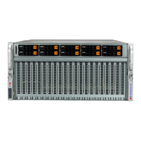
SuperServer SYS-420GU-TNXR User's Manual 1.2 System Features The following views of the system display the main features. Refer to Appendix B for additional specifications. Front View Hybrid NVME Drives Control Panel CPU1 CPU2 Figure 1-1. Front View Expansion Slot Locations... -
Page 11: Control Panel
Chapter 1: Introduction Control Panel Figure 1-2. Control Panel Control Panel Features Item Feature Description The main power switch applies or removes primary power from the power supply to Power button the server but maintains standby power. The unit identification (UID) button turns on or off the blue light function of the UID button/LED Information LED and a blue LED on the rear of the chassis. -
Page 12: Rear View
SuperServer SYS-420GU-TNXR User's Manual Rear View PSU Release Handle Eight Expansion Slots PSU LED Indicator Power Supply Modules Figure 1-3. System: Rear View Expansion Slot Locations Item Description Controlled By Riser Slot1 OPROM SW2-PCIE0 Riser Slot2 OPROM CPU1 Riser Slot3 OPROM... -
Page 13: System Architecture
Chapter 1: Introduction 1.3 System Architecture This section shows the locations of the system's main components. Main Components 32 DIMM Slots Motherboard System Fans HDD Drive Module Figure 1-4. Main Component Locations... -
Page 14: Motherboard Layout
SuperServer SYS-420GU-TNXR User's Manual 1.4 Motherboard Layout Below is a layout of the X12DGU motherboard with jumper, connector and LED locations shown. See the table on the following page for descriptions. For detailed descriptions, pinout information and jumper settings, refer to... -
Page 15: Quick Reference Table
Chapter 1: Introduction Quick Reference Table Jumper Description Default Setting JBT1 CMOS Clear Open (Normal) JPME1 Manufacturing Mode Select Pins 1-2: normal JUID UID LED/BMC Reset Jumper Pins 1-2: UID LED BMC and PCH I²C/SDA to VRM and JVRM1/JVRM2 Pins 1/3 BMC I²C/SDA for VRM BMC and PCH I²C/SCL to VRM Select JWD1 Watch Dog Jumper... - Page 16 SuperServer SYS-420GU-TNXR User's Manual JCPU1_A_AIOM1/ JCPU1_B_AIOM1/ PCIe 4.0 x16 SlimSAS connectors for AIOM Networking AOC JCPU2_A_AIOM1/ JCPU2_B_AIOM1 J_CPU1_AIOMSB1/ Connectors for AIOM Networking AOC J_CPU2_AIOMSB1 US1_NVME1/ US2_NEME1/ PCIe 4.0 x16 SlimSAS connectors for NVMe devices US3_NVME1/ US4_NVME1 US1_A_NIC1~2/ US1_B_NIC1~2/ US2_A_NIC1~2/ US2_B_NIC1~2/ PCIe 4.0 x16 SlimSAS connectors for I/O riser cards...
-
Page 17: System Block Diagram
Chapter 1: Introduction System Block Diagram The block diagram below shows the connections and relationships between the subsystems and major components of the overall system. X12DGU PCIe [48..63] PCIe [64..79] PCIe [48..63] PCIe [64..79] NIC2 NIC2 PCIe [80..95] PCIe [80..95] PEX2 NIC1 NIC1... -
Page 18: Chapter 2 Server Installation
SuperServer SYS-420GU-TNXR User's Manual Chapter 2 Server Installation 2.1 Overview This chapter provides advice and instructions for mounting your system in a server rack. If your system is not already fully integrated with processors, system memory etc., refer to Chapter 3 for details on installing those specific components. -
Page 19: Server Precautions
Chapter 2: Server Installation • In single rack installations, stabilizers should be attached to the rack. In multiple rack in- stallations, the racks should be coupled together. • Always make sure the rack is stable before extending a server or other component from the rack. -
Page 20: Mechanical Loading
SuperServer SYS-420GU-TNXR User's Manual Mechanical Loading Equipment should be mounted into a rack so that a hazardous condition does not arise due to uneven mechanical loading. Circuit Overloading Consideration should be given to the connection of the equipment to the power supply circuitry and the effect that any possible overloading of circuits might have on overcurrent protection and power supply wiring. -
Page 21: Rack Mounting
Chapter 2: Server Installation 2.3 Rack Mounting This section provides information on installing a 4U chassis into a rack unit with the rails provided. There are a variety of rack units on the market, so the assembly procedure may differ slightly. Also refer to the installation instructions for your rack unit. Note: This rail will fit a rack between 26.5"and 36.4"... -
Page 22: Installing The Inner Rails
SuperServer SYS-420GU-TNXR User's Manual Installing the Inner Rails Installing the Inner Rail to the Chassis 1. Place the correct rail on the side of the chassis, aligning the hooks of the chassis with the inner rail holes. Make sure the rail faces "outward" so that it will fit the rack's mounting bracket. -
Page 23: Installing The Outer Rails Onto The Rack
Chapter 2: Server Installation Installing the Outer Rails onto the Rack Each end of the assembled outer rail includes a bracket with hooks and square, spring-loaded pegs to fit into the square holes in your rack. Installing the Outer Rail 1. -
Page 24: Installing The Server Onto The Rack
SuperServer SYS-420GU-TNXR User's Manual Installing the Server onto the Rack Once rails are attached to the chassis and the rack, you can install the server. Installing the Chassis into a Rack Caution: The assembled system may weigh over 160 lbs. Use a lift and multiple people to move it. -
Page 25: Removing The Chassis From The Rack
Chapter 2: Server Installation Removing the Chassis from the Rack Caution! The system is heavy. It is dangerous for a single person to remove it from the rack. Have sufficient personnel or use a lift to support the chassis. 1. Loosen the thumbscrews that hold the front of the server to the rack. 2. -
Page 26: Chapter 3 Maintenance And Component Installation
SuperServer SYS-420GU-TNXR User's Manual Chapter 3 Maintenance and Component Installation This chapter provides instructions on installing and replacing main system components. To prevent compatibility issues, only use components that match the specifications and/or part numbers given. Installation or replacement of most components require that power first be removed from the system. -
Page 27: Accessing The System
Chapter 3: Maintenance and Component Installation 3.2 Accessing the System Located at the chassis front is a storage tray that houses 10 2.5" SATA3/NVMe drives. To reach the mid-chassis fans, the middle section of the top cover can be opened. Finally, the rear and middle cover can be removed to access the expansion tray and the motherboard below the expansion tray. - Page 28 SuperServer SYS-420GU-TNXR User's Manual Opening the Middle Cover 1. Slide the two buttons on the middle cover towards the center. 2. Lift the cover open. Slide Slide Figure 3-2. Removing Middle Cover...
- Page 29 Chapter 3: Maintenance and Component Installation Removing the Rear and Middle Cover 1. Remove the five screws on the top cover at the rear of the chassis. Remove the four screws on the side of the top cover. 2. Slide the two buttons on the middle cover towards the center 3.
-
Page 30: Processor And Heatsink Installation
Thermal grease is pre-applied on a new heatsink. No additional thermal grease is needed. • Refer to the Supermicro website for updates on processor and memory support. • All graphics in this manual are for illustrations only. Your components may look different. - Page 31 Chapter 3: Maintenance and Component Installation 1. The 3rd Gen Intel Xeon Scalable Processor = Cutout = Pin 1 = CPU Key Processor Top View...
- Page 32 SuperServer SYS-420GU-TNXR User's Manual 2. The Processor Carrier Carrier Top View = Cutout = Pin 1 = CPU Key Carrier Bottom View...
- Page 33 Chapter 3: Maintenance and Component Installation 3. Heatsink Note: Exercise extreme care when handling the heatsink. Pay attention to the edges of heatsink fins, which can be sharp! To avoid damaging the heatsink, please do not apply excessive force on the fins.
-
Page 34: Overview Of The Cpu Socket
SuperServer SYS-420GU-TNXR User's Manual Overview of the CPU Socket The CPU socket is protected by a plastic protective cover. Plastic Protective Cover CPU Socket... -
Page 35: Overview Of The Processor Carrier Assembly
Chapter 3: Maintenance and Component Installation Overview of the Processor Carrier Assembly The processor carrier assembly contains a Intel® Xeon® Scalable Processor and a processor carrier. Carefully follow the instructions given in the installation section to place a processor into the carrier to create a processor carrier. 1. -
Page 36: Overview Of The Processor Heatsink Module
SuperServer SYS-420GU-TNXR User's Manual Overview of the Processor Heatsink Module The Processor Heatsink Module (PHM) contains a heatsink, a processor carrier, and the Intel® Xeon® Scalable Processor 1. Heatsink 2. Processor Carrier 3. The Intel® Xeon® Scalable Processor Processor Bottom View... -
Page 37: Creating The Processor Carrier Assembly
Chapter 3: Maintenance and Component Installation Creating the Processor Carrier Assembly The processor carrier assembly contains a Intel® Xeon® Scalable Processor and a processor carrier. To create the processor carrier assembly, please follow the steps below: 1. Hold the processor with the LGA lands (with Gold CPU contacts) facing down. Locate the small, gold triangle at the corner of the processor and the corresponding hollowed triangle on the processor carrier as shown in the graphics below. - Page 38 SuperServer SYS-420GU-TNXR User's Manual 1. Locate the lever on the CPU socket and press the lever down as shown below. Lever 2. Using Pin 1 as a guide, carefully align the CPU keys (A & B) on the processor against the CPU keys on the carrier (a &...
- Page 39 Chapter 3: Maintenance and Component Installation 1. After the processor is placed inside the carrier, examine the four sides of the processor, making sure that the processor is properly seated on the carrier. Processor Carrier Processor Carrier Assembly Assembly (Bottom View) (Top View)
-
Page 40: Creating The Processor Heatsink Module (Phm)
SuperServer SYS-420GU-TNXR User's Manual Creating the Processor Heatsink Module (PHM) After creating the processor carrier assembly, please follow the instructions below to mount the processor carrier into the heatsink to form the processor heatsink module (PHM). Note: If this is a new heatsink, the thermal grease has been pre-applied on the underside. -
Page 41: Preparing The Cpu Socket For Installation
Chapter 3: Maintenance and Component Installation Preparing the CPU Socket for Installation This motherboard comes with a plastic protective cover installed on the CPU socket. Remove it from the socket to install the Processor Heatsink Module (PHM). Gently pull up one corner of the plastic protective cover to remove it. -
Page 42: Preparing To Install The Processor Heatsink Module (Phm) Into The Cpu Socket
SuperServer SYS-420GU-TNXR User's Manual Preparing to Install the Processor Heatsink Module (PHM) into the CPU Socket After assembling the Processor Heatsink Module (PHM), you are ready to install it into the CPU socket. To ensure the proper installation, please follow the procedures below: 1. -
Page 43: Installing The Processor Heatsink Module (Phm)
Chapter 3: Maintenance and Component Installation Installing the Processor Heatsink Module (PHM) 1. Align peek nut "A", which is next to the triangle (Pin 1) on the heatsink, against threaded fastener "a" on the CPU socket. Then align peek nuts "B", "C", "D" on the heatsink against threaded fasteners "b", "c", "d"... - Page 44 SuperServer SYS-420GU-TNXR User's Manual 1. With a T30-bit screwdriver, tighten all peek nuts in the sequence of "A", "B", "C", and "D" with even pressure. To avoid damaging the processor or socket, do not use a force greater than 12 lbf-in when tightening the screws.
-
Page 45: Removing The Processor Heatsink Module From The Cpu Socket
Chapter 3: Maintenance and Component Installation Removing the Processor Heatsink Module from the CPU Socket Before removing the processor heatsink module (PHM) from the motherboard, unplug the AC power cord from all power supplies after shutting down the system. Then follow the steps below: 1. -
Page 46: Removing The Carrier Assembly From The Processor Heatsink Module (Phm)
SuperServer SYS-420GU-TNXR User's Manual Removing the Carrier Assembly from the Processor Heatsink Module (PHM) To remove the processor carrier assembly from the PHM, please follow the steps below: 1. Detach four plastic clips (marked a, b, c, d) on the processor carrier assembly from the four corners of heatsink (marked A, B, C, D) in the drawings below. -
Page 47: Removing The Processor From The Processor Carrier Assembly
Chapter 3: Maintenance and Component Installation Removing the Processor from the Processor Carrier Assembly Once you have removed the processor carrier assembly from the PHM, you are ready to remove the processor from the processor carrier by following the steps below. 1. -
Page 48: Memory Installation
SuperServer SYS-420GU-TNXR User's Manual 3.4 Memory Installation Note: Check the Supermicro website for recommended memory modules. Important: Exercise extreme care when installing or removing DIMM modules to prevent any possible damage. Memory Support The X12DGU supports RDIMM/LRDIMM DDR4 ECC memory with speeds of 3200/2933/2666 MHz in 32 memory slots and up to 8TB Intel Optane PMem 200 Series. -
Page 49: Memory Population Table For Intel® Xeon® Scalable Processor
Chapter 3: Maintenance and Component Installation Memory Population Table for Intel® Xeon® Scalable Processor DDR4 Memory Population Table for X12DP 32-DIMM Motherboards When 1 CPU is used: Memory Population Sequence 1 CPU & 1 DIMM CPU1: P1-DIMMA1 1 CPU & 2 DIMMs CPU1: P1-DIMMA1/P1-DIMME1 (Note) 1 CPU &... -
Page 50: Dimm Module Population Sequence
SuperServer SYS-420GU-TNXR User's Manual DIMM Module Population Sequence When installing memory modules, the DIMM slots should be populated in the following order: DIMMA1, DIMME1, DIMMC1, DIMMG1, DIMMB1, DIMMF1, DIMMD1, DIMMH1, then DIMMA2, DIMME2, DIMMC2, DIMMG2, DIMMB2, DIMMF2, DIMMD2, DIMMH2. •... -
Page 51: Dimm Installation
Chapter 3: Maintenance and Component Installation DIMM Installation US3_B_UBB2 US1_B_UBB2 US1_A_UBB2 US1_B_UBB1 US1_A_UBB1 US2_B_UBB2 US2_A_UBB2 US2_B_UBB1 US2_A_UBB1 US3_A_UBB2 US3_B_UBB1 US3_A_UBB1 US4_B_UBB2 US4_A_UBB2 US4_B_UBB1 US4_A_UBB1 SW1 UBB1B SW1 UBB0A SW2 UBB1B SW2 UBB1A SW3 UBB1B SW1 UBB1A SW1 UBB0B SW2 UBB0B SW2 UBB0A SW3 UBB1A SW3 UBB0B... -
Page 52: Motherboard Battery
SuperServer SYS-420GU-TNXR User's Manual 3.5 Motherboard Battery The motherboard uses non-volatile memory to retain system information when system power is removed. This memory is powered by a lithium battery residing on the motherboard. Replacing the Battery Begin by removing power from the system as described in section 3.1. -
Page 53: Storage Drives
Safe to remove NVMe device Green Blinking at 1 Hz Attention state- do not remove NVMe device Note: Enterprise level hard disk drives are recommended for use in Supermicro chassis and servers. For information on recommended HDDs, see the Supermicro website, http://www. supermicro.com/products/nfo/files/storage/SBB-HDDCompList.pdf. -
Page 54: Removing/Installing Drives
SuperServer SYS-420GU-TNXR User's Manual Removing/Installing Drives Removing Drive Carriers from the Chassis 1. Press the release button on the drive carrier. This extends the drive carrier handle. 2. Use the handle to pull the drive and its carrier out of the chassis as shown below. - Page 55 Chapter 3: Maintenance and Component Installation Installing a 2.5" Hard Drive 1. Place the hard drive carrier on a flat surface. 2. The physical size of the drive does not permit using the stubs to hold the right side of the drive.
-
Page 56: Hot-Swap For Nvme Drives
SuperServer SYS-420GU-TNXR User's Manual Hot-Swap for NVMe Drives Supermicro servers support NVMe surprise hot-swap. For even better data security, NVMe orderly hot-swap is recommended. NVMe drives can be ejected and replaced remotely using IPMI. Ejecting a Drive 1. IPMI > System > Storage Monitoring > Physical View 2. -
Page 57: Checking The Temperature Of An Nvme Drive
Chapter 3: Maintenance and Component Installation Checking the Temperature of an NVMe Drive There are two ways to check using IPMI. Checking a Drive • IPMI > System > Storage Monitoring > Physical View - Shows the temperatures of all NVMe drives •... -
Page 58: Storage Tray
SuperServer SYS-420GU-TNXR User's Manual Storage Tray The storage tray can be removed to access the Redstone baseboard Removing the Storage Tray 1. Remove all drives from the storage tray for easier handling. See the Storage Drive instruction at the beginning of this section. -
Page 59: Expansion Cards
3.7 Expansion Cards The system has eight PCIe 4.0 x16 slots for expansion cards. Note: Expansion cards are recommended to be serviced by Supermicro due to the optimized density of the 4U form factor. Installing an Expansion Card in the 4U Chassis 1. -
Page 60: System Fans
SuperServer SYS-420GU-TNXR User's Manual 3.8 System Fans Figure 3-10. CPU Fan Replacement Changing a Mid-Chassis Fan 1. Identify the failed fan using BMC. 2. Open the middle cover as described in Section 3.2. 3. Squeeze both tabs at the side of the fan module and pull the fan out of the chassis. -
Page 61: Overheating
Overheat Temperature Setting Some backplanes allow the overheat temperature to be set at 45, 50, or 55 by changing a jumper setting. For more information, consult the backplane user manual at www.supermicro. com. (Click Support, then the Manuals link.) Responses If the server overheats: 1. -
Page 62: Air Shroud
SuperServer SYS-420GU-TNXR User's Manual Air Shroud Typically the air shrouds do not need to be installed. In the rare instance where the air shroud needs to be replace follow the instructions below. The air shroud will cover half of the motherboard and funnel air from the fans to the CPU heatsinks. -
Page 63: Gpu Air Shroud
Chapter 3: Maintenance and Component Installation GPU Air Shroud Three GPU air shrouds funnel cooling air to the GPUs. The GPU air shroud kit contains a sponge (not shown) that is installed onto the chassis floor to support the UBB. Installing or Replacing the Air Shroud 1. -
Page 64: Power Supply
The SYS-420GU-TNXR features 3000W Titanium Level (96%+) redundant power supply modules. The power modules can be changed without powering down the system. New units can be ordered directly from Supermicro or authorized distributors. These power supplies are auto-switching capable. An amber light will be illuminated on the power supply when the power is off. -
Page 65: Chapter 4 Motherboard Connections
Chapter 4: Motherboard Connections Chapter 4 Motherboard Connections This section describes the connections on the motherboard and provides pinout definitions. Note that depending on how the system is configured, not all connections are required. The LEDs on the motherboard are also described here. A motherboard layout indicating component locations may be found in Chapter Please review the Safety Precautions in... -
Page 66: Headers And Connectors
The JTPM1 header is used to connect a Trusted Platform Module (TPM)/Port 80, which is available from Supermicro (optional). A TPM/Port 80 connector is a security device that supports encryption and authentication in hard drives. It allows the motherboard to deny access if the TPM associated with the hard drive is not installed in the system. - Page 67 Chapter 4: Motherboard Connections 6-pin BMC External I C Header A System Management Bus header for the BMC is located at JIPMB1. Connect the appropriate cable here to use the IPMB I C connection on your system. Refer to the layout for the location of JIPMB1.
- Page 68 Intel Intel C621A chipset. Connecting a proper SATA cable to JS1/JS2/JS3 to use SATA 3.0 connections. Advanced I/O Module (AIOM) Connectors Four Supermicro proprietary Advanced I/O Module (AIOM) connectors that provide two PCIe 4.0 x16 connections to add-on module are located at JCPU1_A_AIOM1/JCPU1_B_ AIOM1/ JCPU2_A_AIOM1/JCPU2_B_AIOM1. JCPU1_A_AIOM1 and JCPU1_B_AIOM1 are connected to CPU1.
-
Page 69: Jumpers
Chapter 4: Motherboard Connections 4.3 Jumpers To modify the operation of the motherboard, jumpers are used to choose between optional settings. Jumpers create shorts between two pins to change the function associated with it. Pin 1 is identified with a square solder pad on the printed circuit board. See the motherboard layout page for jumper locations. - Page 70 SuperServer SYS-420GU-TNXR User's Manual BMC and PCH I²C/SDA to VRM and BMC and PCH I²C/SCl to VRM Select Jumper Use JVRM1 and JVRM2 to select between BMC and PCH I²C/SDA for VRM support or BMC and PCH I²C/SCl for VRM support. Connect a cable to JVRM1 and JVRM2 to enable BMC and PCH I²C/SDA for VRM support.
-
Page 71: Led Indicators
Chapter 4: Motherboard Connections 4.4 LED Indicators BMC LAN LEDs A dedicated BMC LAN connection is provided on the rear side of the motherboard. The LED on the right indicates activity, and the LED on the left indicates the speed of the connection. Refer to the table below for more information. -
Page 72: Input/Output Ports
SuperServer SYS-420GU-TNXR User's Manual 4.5 Input/Output Ports See the figure below for the locations and descriptions of the various I/O ports on the rear of the motherboard. Figure 4-1. Rear I/O Ports Rear I/O Ports Description Description UID LED/BMC reset switch USB1 (USB 3.0) -
Page 73: Front Control Panels
1, located at JFP1, contains header pins for various buttons and LED indications with I²C support for front access. This front control panel headers are designed specifically for use with Supermicro chassis. See the figure below for the pin-out descriptions for JFP1. Power On and BMC/BIOS Status LED Button The Power On and BMC/BIOS Status LED button is located on Pin 1 of the front control panel header located at JFP1. - Page 74 SuperServer SYS-420GU-TNXR User's Manual UID LED The unit identifier LED connection is located on Pin 3 of JFP1. See the figure below for more information on JFP1. Fail LED (Information LED for OH/FF/PF) The Fail LED (Information LED for OH/Fan Fail/PWR Fail) connection is located on Pin 4 of JFP1.
- Page 75 Chapter 4: Motherboard Connections Standby Power LED The LED indicator for standby power is located on Pin 8 of JFP1. If this LED is on, standby power is on. RoT (Root of Trust) Power LED The Power LED for RoT (Root of Trust) connection is located on Pin 9 of JFP1. If this LED is on, power for the RoT chip is on.
-
Page 76: Chapter 5 Software
1. Create a method to access the Microsoft Windows installation ISO file. That can be a USB flash, media drive, or the BMC KVM console. 2. Retrieve the proper RST/RSTe driver. Go to the Supermicro web page for your motherboard and click on "Download the Latest Drivers and Utilities", select the proper driver, and copy it to a USB flash drive. - Page 77 Chapter 5: Software 4. During Windows Setup, continue to the dialog where you select the drives on which to install Windows. If the disk you want to use is not listed, click on “Load driver” link at the bottom left corner. Figure 5-2.
-
Page 78: Driver Installation
The Supermicro website contains drivers and utilities for your system at https://www. supermicro.com/wdl/driver. Some of these must be installed, such as the chipset driver. After accessing the website, go into the CDR_Images (in the parent directory of the above link) and locate the ISO file for your motherboard. Download this file to a USB flash drive or media drive (you may also use a utility to extract the ISO file if preferred). -
Page 79: Superdoctor ® 5
5.3 SuperDoctor ® The Supermicro SuperDoctor 5 is a program that functions in a command-line or web-based interface for Windows and Linux operating systems. The program monitors such system health information as CPU temperature, system voltages, system power consumption, fan speed, and provides alerts via email or Simple Network Management Protocol (SNMP). -
Page 80: Bmc
There are several BIOS settings that are related to BMC. For general documentation and information on BMC, visit our website at: www.supermicro.com/en/solutions/management-software/bmc-resources BMC ADMIN User Password For security, each system is assigned a unique default BMC password for the ADMIN user. -
Page 81: Chapter 6 Optional Components
Chapter 6: Optional Components Chapter 6 Optional Components This chapter describes optional system components and installation procedures. 6.1 Optional Parts List Redstone GPU Optional Parts List Description Part Number Quantity GPU Heatsink SNK-P4009P GPU Air shroud MCP-310-45805-0B Sheet-Metal Tray for Redstone UBB MCP-240-45808-0N PCIe Transition Board AOM-PCIE4-SXM4-Q-P... -
Page 82: Plx2 To Gpu2 Cable
Chapter 6: Optional Components PLX2 to GPU2 Cable Two 75-cm, slimSAS cables (CBL-SAST-1275L4F-85) used to connect the GPU to the motherboard. PLX3 to GPU3 Cable Two 60-cm, slimSAS cables (CBL-SAST-1255L4F-85) used to connect the GPU to the motherboard. PLX4 to GPU4 Cable Two 40-cm, slimSAS cables (CBL-SAST-1240L4F-85) used to connect the GPU to the motherboard. -
Page 83: Intel Virtual Raid On Cpu (Vroc)
Chapter 6: Optional Components 6.2 Intel Virtual RAID on CPU (VROC) Intel Virtual RAID on CPU (Intel VROC) is an enterprise RAID solution for NVMe SSDs ® directly attached to Intel Xeon Scalable processors. Intel Volume Management Device (VMD) is an integrated controller inside the CPU PCIe root complex. •... -
Page 84: Additional Information
Chapter 6: Optional Components Additional Information Additional information is available on the product page for the Supermicro add-on card and the linked manuals. www.supermicro.com/products/accessories/addon/AOC-VROCxxxMOD.cfm Hardware Key The Intel VROC hardware key is a license key that detects the Intel VROC SKU and activates the function accordingly. -
Page 85: Enabling Nvme Raid
Chapter 6: Optional Components Enabling NVMe RAID RAID for NVMe SSDs must be enabled through the UEFI BIOS. 1. Install the patch as described in the Restrictions and Requirements section on a previous page. 2. Reboot the server. 3. Press [DEL] key to enter BIOS. 4. - Page 86 Chapter 6: Optional Components Figure 6-2. BIOS VMD Setting Examples...
- Page 87 Chapter 6: Optional Components 13. Select Strip Size (Default 64KB). 14. Select Create Volume. 15. If another RAID is needed, start again at step 6. 16. Press [F4] to save and reboot. Figure 6-3. Created Volume without Figure 6-4. Created Volume with enabling RAID spanned over VMD enabling RAID spanned over VMD Controller...
-
Page 88: Status Indications
Chapter 6: Optional Components Status Indications An LED indicator on the drive carrier shows the RAID status of the drive. Drive Carrier Status LED Indicator Status State (red) Normal function Locating 4 Hz blink Fault Solid on Rebuilding 1 Hz Blink IBPI SFF 8489 Defined Status LED States Hot Swap Drives Intel VMD enables hot-plug and hot-unplug for NVMe SSDs, whether from Intel or other... -
Page 89: Chapter 7 Troubleshooting And Support
Chapter 7 Troubleshooting and Support 7.1 Information Resources Website A great deal of information is available on the Supermicro website, supermicro.com. Figure 7-1. Supermicro Website • Specifications for servers and other hardware are available by clicking the Products option. •... -
Page 90: Baseboard Management Controller (Bmc)
Security Center for recent security notices Supermicro Phone and Addresses 7.2 Baseboard Management Controller (BMC) The system supports the Baseboard Management Controller (BMC). BMC is used to provide remote access, monitoring and management. There are several BIOS settings that are related to BMC. -
Page 91: Troubleshooting Procedures
Chapter 7: Troubleshooting and Support 7.3 Troubleshooting Procedures Use the following procedures to troubleshoot your system. If you have followed all of the procedures below and still need assistance, refer to the Technical Support Procedures Returning Merchandise for Service section(s) in this chapter. Power down the system before changing any non hot-swap hardware components. -
Page 92: No Video
• Memory: Make sure that the memory modules are supported. Refer to the product page on our website at www.supermicro.com. Test the modules using memtest86 or a similar utility. • Storage drives: Make sure that all drives work properly. Replace if necessary. - Page 93 Also check the Control panel Overheat LED. • Adequate power supply: Make sure that the power supply provides adequate power to the system. Make sure that all power connectors are connected. Refer to the Supermicro website for the minimum power requirements. •...
-
Page 94: Crash Dump Using Bmc
In the event of a processor internal error (IERR) that crashes your system, you may want to provide information to support staff. You can download a crash dump of status information using BMC. The BMC manual is available at https://www.supermicro.com/en/solutions/ management-software/bmc-resources. Check BMC Error Log 1. -
Page 95: Uefi Bios Recovery
Warning: Do not upgrade the BIOS unless your system has a BIOS-related issue. Flashing the wrong BIOS can cause irreparable damage to the system. In no event shall Supermicro be liable for direct, indirect, special, incidental, or consequential damages arising from a BIOS update. - Page 96 USB device or a writable CD/DVD. Note 1: If you cannot locate the "Super.ROM" file in your drive disk, visit our website at www.supermicro.com to download the BIOS package. Extract the BIOS binary image into a USB flash device and rename it "Super.ROM" for the BIOS recovery use.
- Page 97 Chapter 7: Troubleshooting and Support Note: At this point, you may decide if you want to start the BIOS recovery. If you decide to proceed with BIOS recovery, follow the procedures below. 4. When the screen as shown above displays, use the arrow keys to select the item "Proceed with flash update"...
- Page 98 Chapter 7: Troubleshooting and Support 7. Press <Del> continuously during system boot to enter the BIOS Setup utility. From the top of the tool bar, select Boot to enter the submenu. From the submenu list, select Boot Option #1 as shown below. Then, set Boot Option #1 to [UEFI AP:UEFI: Built-in EFI Shell]. Press <F4>...
- Page 99 Chapter 7: Troubleshooting and Support Note: Do not interrupt this process until the BIOS flashing is complete. 9. The screen above indicates that the BIOS update process is complete. When you see the screen above, unplug the AC power cable from the power supply, clear CMOS, and plug the AC power cable in the power supply again to power on the system.
-
Page 100: Cmos Clear
Chapter 7: Troubleshooting and Support 7.6 CMOS Clear JBT1 is used to clear CMOS, which will also clear any passwords. Instead of pins, this jumper consists of contact pads to prevent accidentally clearing the contents of CMOS. To Clear CMOS 1. -
Page 101: Where To Get Replacement Components
7.7 Where to Get Replacement Components If you need replacement parts for your system, to ensure the highest level of professional service and technical support, purchase exclusively from our Supermicro Authorized Distributors/System Integrators/Resellers. A list can be found at: http://www.supermicro.com. -
Page 102: Vendor Support Filing System
For issues related to Red Hat Enterprise Linux, since it is a subscription based OS, contact your account representative. 7.9 Feedback Supermicro values your feedback as we strive to improve our customer experience in all facets of our business. Please email us at techwriterteam@supermicro.com to provide feedback on our manuals. -
Page 103: Appendix A Standardized Warning Statements For Ac Systems
Supermicro's Technical Support department for assistance. Only certified technicians should attempt to install or configure components. Read this appendix in its entirety before installing or configuring components in the Supermicro chassis. These warnings may also be found on our website at http://www.supermicro.com/about/... - Page 104 Appendix A: Standardized Warning Statements Warnung WICHTIGE SICHERHEITSHINWEISE Dieses Warnsymbol bedeutet Gefahr. Sie befinden sich in einer Situation, die zu Verletzungen führen kann. Machen Sie sich vor der Arbeit mit Geräten mit den Gefahren elektrischer Schaltungen und den üblichen Verfahren zur Vorbeugung vor Unfällen vertraut. Suchen Sie mit der am Ende jeder Warnung angegebenen Anweisungsnummer nach der jeweiligen Übersetzung in den übersetzten Sicherheitshinweisen, die zusammen mit diesem Gerät ausgeliefert wurden.
- Page 105 SuperServer SYS-420GU-TNXR User's Manual . ٌ ا ك ً ف حالة و ٌ يك أى تتسبب ف اصابة جسذ ة ٌ هذا الزهز ع ٌ خطز !تحذ ز قبل أى تعول عىل أي هعذات،يك عىل علن بالوخاطز ال ا ٌجوة عي الذوائز...
- Page 106 Appendix A: Standardized Warning Statements Warnung Vor dem Anschließen des Systems an die Stromquelle die Installationsanweisungen lesen. ¡Advertencia! Lea las instrucciones de instalación antes de conectar el sistema a la red de alimentación. Attention Avant de brancher le système sur la source d'alimentation, consulter les directives d'installation. .יש...
- Page 107 SuperServer SYS-420GU-TNXR User's Manual Warnung Dieses Produkt ist darauf angewiesen, dass im Gebäude ein Kurzschluss- bzw. Überstromschutz installiert ist. Stellen Sie sicher, dass der Nennwert der Schutzvorrichtung nicht mehr als: 250 V, 20 A beträgt. ¡Advertencia! Este equipo utiliza el sistema de protección contra cortocircuitos (o sobrecorrientes) del edificio.
- Page 108 Appendix A: Standardized Warning Statements Power Disconnection Warning Warning! The system must be disconnected from all sources of power and the power cord removed from the power supply module(s) before accessing the chassis interior to install or remove system components. 電源切断の警告...
- Page 109 SuperServer SYS-420GU-TNXR User's Manual يجب فصم اننظاو من جميع مصادر انطاقت وإ ز انت سهك انكهرباء من وحدة امداد انطاقت قبم انىصىل إىن امنناطق انداخهيت نههيكم نتثبيج أو إ ز انت مكىناث الجهاز 경고! 시스템에 부품들을 장착하거나 제거하기 위해서는 섀시 내부에 접근하기 전에 반드시 전원...
- Page 110 Appendix A: Standardized Warning Statements Attention Il est vivement recommandé de confier l'installation, le remplacement et la maintenance de ces équipements à des personnels qualifiés et expérimentés. !אזהרה .צוות מוסמך בלבד רשאי להתקין, להחליף את הציוד או לתת שירות עבור הציוד واملدربيه...
- Page 111 SuperServer SYS-420GU-TNXR User's Manual Warnung Diese Einheit ist zur Installation in Bereichen mit beschränktem Zutritt vorgesehen. Der Zutritt zu derartigen Bereichen ist nur mit einem Spezialwerkzeug, Schloss und Schlüssel oder einer sonstigen Sicherheitsvorkehrung möglich. ¡Advertencia! Esta unidad ha sido diseñada para instalación en áreas de acceso restringido. Sólo puede obtenerse acceso a una de estas áreas mediante la utilización de una herramienta especial,...
- Page 112 Appendix A: Standardized Warning Statements Battery Handling Warning! There is the danger of explosion if the battery is replaced incorrectly. Replace the battery only with the same or equivalent type recommended by the manufacturer. Dispose of used batteries according to the manufacturer's instructions 電池の取り扱い...
- Page 113 SuperServer SYS-420GU-TNXR User's Manual هناك خطر من انفجار يف حالة اسحبذال البطارية بطريقة غري صحيحة فعليل اسحبذال البطارية فقط بنفس النىع أو ما يعادلها مام أوصث به الرشمة املصنعة جخلص من البطاريات املسحعملة وفقا لحعليامت الرشمة الصانعة 경고! 배터리가 올바르게 교체되지 않으면 폭발의 위험이 있습니다. 기존 배터리와 동일하거나 제...
- Page 114 Appendix A: Standardized Warning Statements ¡Advertencia! Puede que esta unidad tenga más de una conexión para fuentes de alimentación. Para cortar por completo el suministro de energía, deben desconectarse todas las conexiones. Attention Cette unité peut avoir plus d'une connexion d'alimentation. Pour supprimer toute tension et tout courant électrique de l'unité, toutes les connexions d'alimentation doivent être débranchées.
- Page 115 SuperServer SYS-420GU-TNXR User's Manual Backplane Voltage Warning! Hazardous voltage or energy is present on the backplane when the system is operating. Use caution when servicing. バックプレーンの電圧 システムの稼働中は危険な電圧または電力が、 バックプレーン上にかかっています。 修理する際には注意く ださい。 警告 当系统正在进行时,背板上有很危险的电压或能量,进行维修时务必小心。 警告 當系統正在進行時,背板上有危險的電壓或能量,進行維修時務必小心。 Warnung Wenn das System in Betrieb ist, treten auf der Rückwandplatine gefährliche Spannungen oder Energien auf.
- Page 116 Appendix A: Standardized Warning Statements هناك خطز مه التيار الكهزبايئ أوالطاقة املىجىدة عىل اللىحة عندما يكىن النظام يعمل كه حذ ر ا عند خدمة هذا الجهاس 경고! 시스템이 동작 중일 때 후면판 (Backplane)에는 위험한 전압이나 에너지가 발생 합니다. 서비스 작업 시 주의하십시오. Waarschuwing Een gevaarlijke spanning of energie is aanwezig op de backplane wanneer het systeem in gebruik is.
- Page 117 SuperServer SYS-420GU-TNXR User's Manual תיאום חוקי החשמל הארצי !אזהרה .התקנת הציוד חייבת להיות תואמת לחוקי החשמל המקומיים והארציים تركيب املعدات الكهربائية يجب أن ميتثل للقىاويه املحلية والىطىية املتعلقة بالكهرباء 경고! 현 지역 및 국가의 전기 규정에 따라 장비를 설치해야 합니다.
- Page 118 Appendix A: Standardized Warning Statements Attention La mise au rebut ou le recyclage de ce produit sont généralement soumis à des lois et/ou directives de respect de l'environnement. Renseignez-vous auprès de l'organisme compétent. סילוק המוצר !אזהרה .סילוק סופי של מוצר זה חייב להיות בהתאם להנחיות וחוקי המדינה التخلص...
- Page 119 SuperServer SYS-420GU-TNXR User's Manual Warnung Gefährlich Bewegende Teile. Von den bewegenden Lüfterblätter fern halten. Die Lüfter drehen sich u. U. noch, wenn die Lüfterbaugruppe aus dem Chassis genommen wird. Halten Sie Finger, Schraubendreher und andere Gegenstände von den Öffnungen des Lüftergehäuses entfernt.
- Page 120 Verbindungskabeln, Stromkabeln und/oder Adapater, die Ihre örtlichen Sicherheitsstandards einhalten. Der Gebrauch von anderen Kabeln und Adapter können Fehlfunktionen oder Feuer verursachen. Die Richtlinien untersagen das Nutzen von UL oder CAS zertifizierten Kabeln (mit UL/CSA gekennzeichnet), an Geräten oder Produkten die nicht mit Supermicro gekennzeichnet sind.
- Page 121 .قيرح وأ لطع يف ببستي دق ىرخأ تالوحمو تالباك يأ مادختسا .ميلسلا سباقلاو لصوملا مجح لبق نم ةدمتعملا تالباكلا مادختسا تادعملاو ةيئابرهكلا ةزهجألل ةمالسلا نوناق رظحيUL وأCSA ( ةمالع لمحت يتلاوUL/CSA) لبق نم ةددحملاو ةينعملا تاجتنملا ريغ ىرخأ تادعم يأ عمSupermicro.
- Page 122 사항을 준수하여 제공되거나 지정된 연결 혹은 구매 케이블, 전원 케이블 및 AC 어댑터를 사용하십시오. 다른 케이블이나 어댑터를 사용하면 오작동이나 화재가 발생할 수 있습니다. 전기 용품 안전법은 UL 또는 CSA 인증 케이블 (코드에 UL / CSA가 표시된 케이블)을 Supermicro 가 지정한 제품 이외의 전기 장치에 사용하는 것을 금지합니다. Stroomkabel en AC-Adapter...
-
Page 123: Appendix B System Specifications
Appendix B: System Specifications Appendix B System Specifications Processors Dual 3rd Generation Intel® Xeon® Scalable processor Socket P+ (LGA-4189) Chipset Intel® C621A BIOS AMI 32MB SPI Flash EEPROM Memory 32 DIMM slots up to 8TB: 32x 256 GB DRAM 3200/2933/2666MHz ECC DDR4 RDIMM/LRDIMM Storage Drives 10 2.5"... - Page 124 Appendix B: System Specifications Operating Environment Operating Temperature: 10º to 35º C (50º to 95º F) Non-operating Temperature: -40º to 60º C (-40º to 140º F) Operating Relative Humidity: 8% to 90% (non-condensing) Non-operating Relative Humidity: 5% to 95% (non-condensing) Regulatory Compliance FCC, ICES, CE, VCCI, RCM, UKCA, NRTL, CB Applied Directives, Standards...
Need help?
Do you have a question about the SuperServer SYS-420GU-TNXR and is the answer not in the manual?
Questions and answers