
Related Manuals for Avalue Technology EBM-SKLU-B1


Summary of Contents for Avalue Technology EBM-SKLU-B1
- Page 1 EBM-SKLU-B1 Intel® 6th Generation ULT Processor 5.25” Mini Module User’s Manual Ed –27 July 2021 Part No. E2047582702R...
- Page 2 Disclaimer Avalue Technology Inc. reserves the right to make changes, without notice, to any product, including circuits and/or software described or contained in this manual in order to improve design and/or performance. Avalue Technology assumes no responsibility or liability for the...
- Page 3 Applications that are described in this manual are for illustration purposes only. Avalue Technology Inc. makes no representation or warranty that such application will be suitable for the specified use without further testing or modification.
- Page 4 A product returned without proof of the purchase date is not eligible for warranty service. Write the RMA number visibly on the outside of the package and ship it prepaid to your dealer. 4 EBM-SKLU-B1 User’s Manual...
-
Page 5: Table Of Contents
Amplifier connector (JSPK_L1) ....................28 2.3.20 SPI connector (JSPI1) ....................... 29 2.3.21 EC Debug connector (JEC1) ..................... 29 2.3.22 Battery connector (JBAT1) ......................30 2.3.23 LPC connector (JLPC1) ......................30 3.BIOS Setup ........................31 Introduction ......................32 EBM-SKLU-B1 User’s Manual... - Page 6 System Agent (SA) Configuration ..................52 3.6.3.1.1 Graphics Configuration ......................53 3.6.3.1.2 Memory Configuration ......................54 3.6.3.2 PCH-IO Configuration ......................55 3.6.3.2.1 PCI Express Configuration ....................55 3.6.3.2.2 USB Configuration ......................... 58 3.6.3.2.3 HD Audio Configuration ......................58 6 EBM-SKLU-B1 User’s Manual...
- Page 7 Install Touch Driver ....................66 Install ME Driver ...................... 69 Install VGA Driver ....................70 Install Ethernet Driver ....................72 Install Serial IO Driver ..................... 74 Install TPM2.0 Driver ....................76 Install USB3.0 Driver ....................77 5. Mechanical Drawing ....................78 EBM-SKLU-B1 User’s Manual...
-
Page 8: Getting Started
1.2 Packing List Before you begin installing your single board, please make sure that the following materials have been shipped: 1 x EBM-SKLU-B1 Intel® 6th Generation ULT Processor 5.25” Mini Module 8 EBM-SKLU-B1 User’s Manual... -
Page 9: Document Amendment History
User’s Manual 1.3 Document Amendment History Revision Date Comment July 2021 Avalue Initial Release EBM-SKLU-B1 User’s Manual... -
Page 10: Manual Objectives
We strongly recommend that you study this manual carefully before attempting to set up EBM-SKLU-B1 or change the standard configurations. Whilst all the necessary information is available in this manual we would recommend that unless you are confident, you contact your supplier for guidance. -
Page 11: System Specifications
16 bit GPIO (2 x 10 pin wafer w/2.0mm pitch ) 8 x In, 8 x Out SATA Power 1 x 1 x 2 pin wafer w/2.0mm pitch for SATA Power CPU/System 1 x 4 pin header w/2.54mm pitch EBM-SKLU-B1 User’s Manual 11... - Page 12 Amplifier 2W Per Channel Line-Out and Amp Ethernet 1 x Intel I210AT GbE controller LAN Chip 1 x Intel I219LM Gigabit Ethernet PHY LAN Spec. 10/100/1000 Base-Tx compatible Mechanical & Environmental Power +12V ~ +26V Requirement 12 EBM-SKLU-B1 User’s Manual...
- Page 13 5 30 min. per each axis 6 IEC 60068-2-64 Test:Fh 1 One corner , three edges, six faces Drop Test 2 ISTA 2A, IEC-60068-2-32 Test:Ed OS Information Windows 10 IoT Note: Specifications are subject to change without notice. EBM-SKLU-B1 User’s Manual 13...
-
Page 14: Architecture Overview-Block Diagram
EBM-SKLU-B1 User’s Manual 1.6 Architecture Overview—Block Diagram The following block diagram shows the architecture and main components of EBM-SKLU-B1. 14 EBM-SKLU-B1 User’s Manual... -
Page 15: Hardware Configuration
User’s Manual 2. Hardware Configuration EBM-SKLU-B1 User’s Manual 15... -
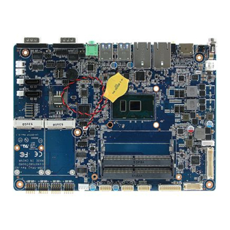
Page 16: Product Overview
EBM-SKLU-B1 User’s Manual 2.1 Product Overview 16 EBM-SKLU-B1 User’s Manual... -
Page 17: Jumper And Connector List
JCOMS1 Clear CMOS 3 x 1 header, pitch 2.00mm Connectors Label Function Note JBKLSEL2 LCD brightness DC/PWM mode select 2 2 x 1 header, pitch 2.00mm JBKL1 LCD Inverter connector 5 x 1 wafer, pitch 2.00mm EBM-SKLU-B1 User’s Manual 17... - Page 18 SATAPW1/2 SATA Power connector 1/2 2 x 1 wafer, pitch 2.00mm SATA1/2 Serial ATA connector 1/2 SIM1 SIM card slot HDMI1 HDMI connector LOUT1 Audio line-out connector JEDP1 eDP_Panel connector 10 x 2 wafer, pitch 1.25mm 18 EBM-SKLU-B1 User’s Manual...
-
Page 19: Setting Jumpers & Connectors
In Serial Port 1 mode RS-232 RS-422 RS-485 In Serial Port 2 mode RS-232 RS-422 RS-485 AT SEL ATX SEL Touch off Touch on 2.3.2 Serial port 1/2 RS-232/422/485 mode select (JCOM_SEL1/2) RS-232* RS-422/ 485 JCOM_SEL1 JCOM_SEL2 * Defaul EBM-SKLU-B1 User’s Manual 19... -
Page 20: Serial Port 1/ 2 Pin9 Signal Select (Jri1/ Jri2)
EBM-SKLU-B1 User’s Manual 2.3.3 Serial port 1/ 2 pin9 signal select (JRI1/ JRI2) Ring* +12V JRI1 JRI2 * Default 2.3.4 Clear CMOS (JCOMS1) Normal* Clear CMOS * Default 20 EBM-SKLU-B1 User’s Manual... -
Page 21: Lcd Brightness Dc/Pwm Mode Select 1/2 (Jbklsel1/2)
User’s Manual 2.3.5 LCD brightness DC/PWM mode select 1/2 (JBKLSEL1/2) PWM Mode* JBKLSEL1 JBKLSEL2 DC Mode OS Driver * Default Note: JBKLSEL1/2 can’t be used simultaneously. 2.3.6 LCD Inverter connector (JBKL1) Signal +12V LVDS_BKLT_EN LVDS_BKLTCTL EBM-SKLU-B1 User’s Manual 21... -
Page 22: Cpu Fan Connector (Cpufan1)
EBM-SKLU-B1 User’s Manual 2.3.7 CPU fan connector (CPUFAN1) Signal EC_TACH0 +12V 2.3.8 Serial port 3/4/5/6 connector (JCOM3/JCOM4/JCOM5/JCOM6) Signal PIN PIN Signal JCOM3 COM_RI# JCOM4 COM_RTS# COM_CTS# JCOM5 COM_DSR# JCOM6 COM_TXD COM_DTR# COM_DCD# COM_RXD 22 EBM-SKLU-B1 User’s Manual... -
Page 23: Edp_Panel Connector (Jedp1)
Signal +V3512_EDP +V3512_EDP EDP_Panel_TXP2 17 EDP_Panel_HPD EDP_Panel_TXN2 15 14 EDP_Panel_AUXP EDP_Panel_TXP1 11 12 EDP_Panel_AUXN EDP_Panel_TXN1 EDP_Panel_TXP0 EDP_Panel_TXP3 EDP_Panel_TXN0 EDP_Panel_TXN3 2.3.10 Front Panel connector (JLED1) Signal PIN PIN Signal PWRBTN# +5VSB LAN2_ACT#_LED +5VSB LAN1_ACT#_LED HDD_LED# +5VSB PWR_LED- EBM-SKLU-B1 User’s Manual 23... -
Page 24: General Purpose I/O Connector (Jdio1)
General purpose I/O connector (JDIO1) Signal PIN PIN Signal SMB_DATA_5655 17 18 SMB_CLK_5655 DIO_GP27 DIO_GP17 DIO_GP26 DIO_GP16 DIO_GP25 DIO_GP15 DIO_GP24 DIO_GP14 DIO_GP23 DIO_GP13 DIO_GP22 DIO_GP12 DIO_GP21 DIO_GP11 DIO_GP20 DIO_GP10 2.3.12 Touch panel connector (JTOUCH1) Signal THX+ THX- THPROBE_R THY+ THY- 24 EBM-SKLU-B1 User’s Manual... -
Page 25: Sata Power Connector 1/2 (Satapw1/2)
User’s Manual 2.3.13 SATA Power connector 1/2 (SATAPW1/2) Signal SATAPW2 SATAPW1 2.3.14 Power connector (DCIN1) Signal Signal +VIN_26V +VIN_26V EBM-SKLU-B1 User’s Manual 25... -
Page 26: Lvds Connector (Jlvds1)
10 LVDS_DATA0_P LVDS_DATA1_N 11 12 LVDS_DATA0_N LVDS_DATA3_P 15 16 LVDS_DATA2_P LVDS_DATA3_N 17 18 LVDS_DATA2_N LVDS_DATA5_P 21 22 LVDS_DATA4_P LVDS_DATA5_N 23 24 LVDS_DATA4_N LVDS_DATA7_P 27 28 LVDS_DATA6_P LVDS_DATA7_N 29 30 LVDS_DATA6_N LVDS_CLK2_P LVDS_CLK1_P LVDS_CLK2_N LVDS_CLK1_N +12V +12V 26 EBM-SKLU-B1 User’s Manual... -
Page 27: Usb Connector (Jusb3)
User’s Manual 2.3.16 USB connector (JUSB3) Signal PIN PIN Signal USB_Z_PP5 USB_Z_PP6 USB_Z_PN5 USB_Z_PN6 +5VSB +5VSB 2.3.17 USB connector (JUSB4) Signal PIN PIN Signal USB_Z_PP7 USB_Z_PP8 USB_Z_PN7 USB_Z_PN8 +5VSB +5VSB EBM-SKLU-B1 User’s Manual 27... -
Page 28: Amplifier Connector (Jspk_R1)
EBM-SKLU-B1 User’s Manual 2.3.18 Amplifier connector (JSPK_R1) Signal SPK_R+ SPK_R- 2.3.19 Amplifier connector (JSPK_L1) Signal SPK_L+ SPK_L- 28 EBM-SKLU-B1 User’s Manual... -
Page 29: Spi Connector (Jspi1)
User’s Manual 2.3.20 SPI connector (JSPI1) Signal PIN PIN Signal HOLD# SPI_SI SPI_SO SPI_CLK SPI0_CS0# +3.3VSB 2.3.21 EC Debug connector (JEC1) Signal EC_SMDAT_DEBUG EC_SMCLK_DEBUG EBM-SKLU-B1 User’s Manual 29... -
Page 30: Battery Connector (Jbat1)
EBM-SKLU-B1 User’s Manual 2.3.22 Battery connector (JBAT1) Signal +RTCBAT 2.3.23 LPC connector (JLPC1) Signal PIN PIN Signal LPC_SERIRQ CLK2_LPC_PORT80 LPC_AD3 LPC_LFRAME# LPC_AD2 RST_PORT80# LPC_AD1 +3.3VSB LPC_AD0 30 EBM-SKLU-B1 User’s Manual... -
Page 31: Bios Setup
User’s Manual 3.BIOS Setup EBM-SKLU-B1 User’s Manual 31... -
Page 32: Introduction
If the message disappears before you respond and you still wish to enter Setup, restart the system to try again by turning it OFF then ON or pressing the "RESET" button on the system case. You may also restart by simultaneously pressing <Ctrl>, <Alt>, and <Delete> keys. 32 EBM-SKLU-B1 User’s Manual... -
Page 33: Using Setup
Note: Some of the navigation keys differ from one screen to another. To Display a Sub Menu Use the arrow keys to move the cursor to the sub menu you want. Then press <Enter>. A “” pointer marks all sub menus. EBM-SKLU-B1 User’s Manual 33... -
Page 34: Getting Help
BIOS Vendor and your systems manufacturer to provide the absolute maximum performance and reliability. Even a seemingly small change to the chipset setup has the potential for causing you to use the override. 34 EBM-SKLU-B1 User’s Manual... -
Page 35: Bios Setup
<Enter> to accept and enter the sub-menu. 3.6.1 Main Menu This section allows you to record some basic hardware configurations in your computer and set the system clock. EBM-SKLU-B1 User’s Manual 35... -
Page 36: System Language
Visit the Avalue website (www.avalue.com.tw) to download the latest product and BIOS information. 3.6.2 Advanced Menu This section allows you to configure your CPU and other system devices for basic operation through the following sub-menus. 36 EBM-SKLU-B1 User’s Manual... -
Page 37: Trusted Computing
Enable or Disable Storage Hierarchy. Enabled[Default], Disabled Enable or Disable Endorsement Endorsement Hierarchy Enabled[Default], Hierarchy. Select the TCG2 Spec Version Support. 1.0[Default], 1.0: the Compatible mode for TPM2.0 UEFI Spec Version Win8/Win10, 1.x: For TCG2 newer spec for Win10. EBM-SKLU-B1 User’s Manual 37... -
Page 38: Apci Settings
Disabled[Default], ErP Function ErP Function (Deep S5). Enabled Off[Default] PWR-On After PWR-Fail AC loss resume. Last state Disabled[Default], 30 sec 40 sec 50 sec Watch Dog Select WatchDog. 1 min 2 min 10 min 30 min 38 EBM-SKLU-B1 User’s Manual... -
Page 39: Amt Configuration
Extension. Note: iAMT H/W is always Disabled Intel AMT enabled. This option just controls the Enabled[Default], BIOS extension execution. If enabled, this requires additional firmware in the SPI device. Disabled[Default] OEMFlag Bit 15: Un-Configure ME Un-Configure ME Enabled, without password. EBM-SKLU-B1 User’s Manual 39... -
Page 40: Pch-Fw Configuration
GPDMA Work-Around[Default], Select the desired fTPM solution to be fTPM Switch Selection MSFT QFE Solution used. 3.6.2.4.1 Firmware Update Configuration Item Option Description Disabled [Default], ME FW Image Re-Flash Enable/Disable Me FW Image Re-Flash function. Enabled 40 EBM-SKLU-B1 User’s Manual... -
Page 41: It8528 Super Io Configuration
Set Parameters of Serial Port 3 (COMC). Serial Port 4 Configuration Set Parameters of Serial Port 4 (COMD). Serial Port 5 Configuration Set Parameters of Serial Port 5 (COME). Serial Port 6 Configuration Set Parameters of Serial Port 6 (COMF). EBM-SKLU-B1 User’s Manual 41... -
Page 42: Serial Port 1 Configuration
3.6.2.5.1 Serial Port 1 Configuration Item Option Description Enabled[Default], Serial Port Enable or Disable Serial Port (COM). Disabled 3.6.2.5.2 Serial Port 2 Configuration Item Option Description Enabled[Default], Serial Port Enable or Disable Serial Port (COM). Disabled 42 EBM-SKLU-B1 User’s Manual... -
Page 43: Serial Port 3 Configuration
3.6.2.5.3 Serial Port 3 Configuration Item Option Description Enabled[Default], Enable or Disable Serial Port Serial Port Disabled (COM). 3.6.2.5.4 Serial Port 4 Configuration Item Option Description Enabled[Default], Enable or Disable Serial Port Serial Port Disabled (COM). EBM-SKLU-B1 User’s Manual 43... -
Page 44: Serial Port 5 Configuration
3.6.2.5.5 Serial Port 5 Configuration Item Option Description Enabled[Default], Serial Port Enable or Disable Serial Port (COM). Disabled 3.6.2.5.6 Serial Port 6 Configuration Item Option Description Enabled[Default], Serial Port Enable or Disable Serial Port (COM). Disabled 44 EBM-SKLU-B1 User’s Manual... -
Page 45: H/W Monitor
3.6.2.6 H/W Monitor Item Options Description Enabled, Smart Fan Function Enables or Disables Smart Fan. Disabled[Default] 3.6.2.7 S5 RTC Wake Settings Item Options Description Wake system from S5 Disabled[Default], Enable or disable System wake on alarm EBM-SKLU-B1 User’s Manual 45... -
Page 46: Serial Port Console Redirection
Select Dynamic Time, System will wake on the current time + Increase minute(s). 3.6.2.8 Serial Port Console Redirection Item Options Description Disabled[Default], Console Redirection Console Redirection Enable or Disable. Enabled 3.6.2.8.1 Legacy Console Redirection Settings 46 EBM-SKLU-B1 User’s Manual... -
Page 47: Cpu Configuration
When enabled, a VMM can utilize the Disabled Intel Virtualization Technology additional hardware capabilities provided Enabled[Default] by Vanderpool Technology. Disabled Turbo Mode Turbo Mode. Enabled[Default] Disabled CPU C states Enable or disable CPU C state. Enabled[Default] EBM-SKLU-B1 User’s Manual 47... -
Page 48: Intel Txt Configuration
EBM-SKLU-B1 User’s Manual C0/C1 Package C State limit Package C State limit. Auto[Default] 3.6.2.10 Intel TXT Configuration 48 EBM-SKLU-B1 User’s Manual... -
Page 49: Sata Configuration
Aggressive LPM Support Disabled state. Enabled[Default] Port 0/1/2 Enable or Disable SATA Port. Disabled, Hard Disk Drive [Default] Identify the SATA port is connected to Solid SATA Device Type Solid State Drive State Drive or Hard Disk Drive. EBM-SKLU-B1 User’s Manual 49... -
Page 50: Network Stack Configuration
EBM-SKLU-B1 User’s Manual 3.6.2.12 Network Stack Configuration Item Options Description Enabled Network Stack Enable/Disable UEFI Network Stack. Disabled[Default] 3.6.2.13 CSM Configuration Item Options Description Enabled CSM Support Enable/Disable CSM Support. Disabled[Default] 50 EBM-SKLU-B1 User’s Manual... -
Page 51: Usb Configuration
Maximum time the device will take before it properly reports itself to the Host Controller. Auto[Default] ‘Auto’ uses default value: for a Root port it is Device power-up delay Manual 100ms, for a Hub port the delay is taken form Hub descriptor. EBM-SKLU-B1 User’s Manual 51... -
Page 52: Chipset
EBM-SKLU-B1 User’s Manual 3.6.3 Chipset 3.6.3.1 System Agent (SA) Configuration Item Option Description Enabled[Default] VT-d VT-d capability. Disabled 52 EBM-SKLU-B1 User’s Manual... -
Page 53: Graphics Configuration
1920x1080 24/2 1680x1050 24/2 Enabled[Default] Active Internal LVDS (eDP->Ch7511- Active LVDS (CH7511) Disabled to-LVDS). LVDS Back Light PWM Select LVDS back light PWM duty. 100%[Default] 200[Default] LVDS Back Light PWM Select LVDS back light PWM Frequency Frequency. EBM-SKLU-B1 User’s Manual 53... -
Page 54: Memory Configuration
Maximum Memory Maximum Memory Frequency Selections in /1800/1867/2000/2133/2200 Frequency Mhz. /2400/2600/2667/2800/2933 /3000/3200 Dynamic[Default] Maximum Value of TOLUD. Dynamic 1GB/1.25GB/1.5GB/1.75GB assignment would adjust TOLUD Max TOLUD /2GB/2.25GB/2.5GB/2.75GB automatically based on largest MMIO length /3GB/3.25GB/3.5GB of installed graphic controller. 54 EBM-SKLU-B1 User’s Manual... -
Page 55: Pch-Io Configuration
User’s Manual 3.6.3.2 PCH-IO Configuration Item Option Description Disabled PCH LAN Controller Enable or disable onboard NIC. Enabled[Default] Enable/Disable LAN Phy driving Disabled[Default] LAN PHY Drives LAN_WAKE# LAN_WAKE# else platform drives Enabled LAN_WAKE#. 3.6.3.2.1 PCI Express Configuration EBM-SKLU-B1 User’s Manual 55... - Page 56 L0s State AUTO – BIOS auto ASPM Support configure DISABLE – Disables ASPM. L0sL1 Auto Disabled L1.1 L1 Substates PCI Express L1 Substates settings. L1.2 L1.1 & L1.2[Default], Auto[Default] Gen1 PCIe Speed Select PCI Express port speed. Gen2 Gen3 56 EBM-SKLU-B1 User’s Manual...
- Page 57 L0s State AUTO – BIOS auto ASPM Support configure DISABLE – Disables ASPM. L0sL1 Auto Disabled L1.1 L1 Substates PCI Express L1 Substates settings. L1.2 L1.1 & L1.2[Default], Auto[Default] Gen1 PCIe Speed Select PCI Express port speed. Gen2 Gen3 EBM-SKLU-B1 User’s Manual 57...
-
Page 58: Usb Configuration
Disabled[Default], and root ports for faster enumeration. Option to disable Compliance Mode. Default FALSE[Default], XHCI Disable Compliance Mode is FALSE to not disable Compliance Mode. TRUE Set TRUE to disable Compliance Mode. 3.6.3.2.3 HD Audio Configuration 58 EBM-SKLU-B1 User’s Manual... -
Page 59: Security
HD Audio Enabled disabled Enabled = HDA will be Auto[Default], unconditionally enabled Auto = HDA will be enabled if present, disabled otherwise. 3.6.4 Security Administrator Password Set setup Administrator Password User Password Set User Password EBM-SKLU-B1 User’s Manual 59... -
Page 60: Secure Boot Menu
1.System running in User mode Secure Boot Enabled with enrolled Platform Key(PK) 2.CSM function is disabled. Secure Boot mode selector. ‘Custom’ Mode enables users to Standard Secure Boot Mode Custom[Default] change Image Execution policy and manage Secure Boot Keys. 60 EBM-SKLU-B1 User’s Manual... -
Page 61: Key Management
User’s Manual 3.6.4.1.1 Key Management Item Option Description Enabled, Install Factory default Secure Boot Keys Provision Factory Default keys Disabled[Default] when System is in Setup Mode. 3.6.5 Boot EBM-SKLU-B1 User’s Manual 61... -
Page 62: Save And Exit
Disabled[Default] initialization of a minimal set of devices Fast Boot Enabled required to launch active boot option. Has no effect for BBS boot options. Boot Option #1 Set the system boot order. 3.6.6 Save and exit 62 EBM-SKLU-B1 User’s Manual... -
Page 63: Save Changes And Reset
This option restores all BIOS settings to the factory default. This option is useful if the controller exhibits unpredictable behavior due to an incorrect or inappropriate BIOS setting. 3.6.6.4 Launch EFI Shell from filesystem device Attempts to Launch EFI Shell application (Shellx64.efi) from one of the available filesystem devices. EBM-SKLU-B1 User’s Manual 63... -
Page 64: Drivers Installation
EBM-SKLU-B1 User’s Manual 4. Drivers Installation Note: Installation procedures and screen shots in this section are for your reference and may not be exactly the same as shown on your screen. 64 EBM-SKLU-B1 User’s Manual... -
Page 65: Install Chipset Driver
All drivers can be found on the Avalue Official Website: http://www.avalue.com.tw. Note: The installation procedures and screen shots in this section are based on Windows 10 operation system. Step 3. Click Install. Step1. Click Next. Step 4. Setup completed. Step 2. Click Accept. EBM-SKLU-B1 User’s Manual 65... -
Page 66: Install Touch Driver
Windows 10 operation system. Step 3. Click Next. Step1. Click Next to start installation. Step 4. Click Next. Step 2. Click Next to proceed setup. Step 5. Click Next. 66 EBM-SKLU-B1 User’s Manual... - Page 67 User’s Manual Step 6. Click OK. Step 9. Click Next. Step 10. Click Next. Step7. Click Next. Step 8. Click Next to proceed setup. Step 11. Click Next. EBM-SKLU-B1 User’s Manual 67...
- Page 68 EBM-SKLU-B1 User’s Manual Step 12. Setup completed 68 EBM-SKLU-B1 User’s Manual...
-
Page 69: Install Me Driver
Windows 10 operation system. Step 3. Click Next to continue installation. Step 4. Installing. Step1. Click Next to start installation. Step 5. Click Finish to complete setup. Step 2. Click Next. EBM-SKLU-B1 User’s Manual 69... -
Page 70: Install Vga Driver
Windows 10 operation system. Step 3. Click Next. Step 1. Click Next to continue installation. Step 4. Click Next. Step 2. Step 5. Click Next. Click Yes to accept license agreement. 70 EBM-SKLU-B1 User’s Manual... - Page 71 User’s Manual Step 6. Click Finish to complete setup. EBM-SKLU-B1 User’s Manual 71...
-
Page 72: Install Ethernet Driver
Windows 10 operation system. Step 3. Click Next. Step 4. Click Next to continue. Step 1. Click Install Drivers and Software to continue installation. Step 2. Click Next. Step 5. Click Install. 72 EBM-SKLU-B1 User’s Manual... - Page 73 User’s Manual Step 6. Installing. Step 7. Click Finish to complete setup. EBM-SKLU-B1 User’s Manual 73...
-
Page 74: Install Serial Io Driver
Note: The installation procedures and screen shots in this section are based on Windows 10 operation system. Step 3. Click Next. Step 4. Click Next. Step 1. Click Next to continue installation. Step 5. Installing. Step 2. Click Next. 74 EBM-SKLU-B1 User’s Manual... - Page 75 User’s Manual Step 6. Click Finish to complete setup. EBM-SKLU-B1 User’s Manual 75...
-
Page 76: Install Tpm2.0 Driver
All drivers can be found on the Avalue Official Website: http://www.avalue.com.tw. Note: The installation procedures and screen shots in this section are based on Windows 10 operation system. Step 3. Setup completed. Step 1. Click Yes to continue setup. Step 2. Installing. 76 EBM-SKLU-B1 User’s Manual... -
Page 77: Install Usb3.0 Driver
Windows 10 operation system. Step 3. Click Next to continue installation. Step 4. Installing. Step1. Click Next to start installation. Step 2. Click Next. Step 5. Click Finish to complete setup. EBM-SKLU-B1 User’s Manual 77... -
Page 78: Mechanical Drawing
EBM-SKLU-B1 User’s Manual 5. Mechanical Drawing 78 EBM-SKLU-B1 User’s Manual... - Page 79 User’s Manual Unit: mm EBM-SKLU-B1 User’s Manual 79...
- Page 80 EBM-SKLU-B1 User’s Manual Unit: mm 80 EBM-SKLU-B1 User’s Manual...
Need help?
Do you have a question about the EBM-SKLU-B1 and is the answer not in the manual?
Questions and answers