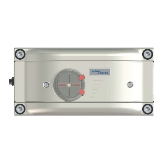
Spirax Sarco SP7-21 Quick Start Manual
Smart positioner
Hide thumbs
Also See for SP7-21:
- Installation and maintenance instructions manual (56 pages) ,
- Manual (64 pages) ,
- Installation and maintenance instructions (4 pages)
Table of Contents
Advertisement
Quick Links
3440754/2
Throughout the document SP7-2* is written
where the information is relevant to all
versions; the SP7-20, SP7-21 and SP7-22.
Where the information is specific it will be
referenced as the version appropriate.
IM-P706-06 CTLS Issue 2
SP7-20, SP7-21 and SP7-22
Smart Positioner
Quick start guide
SP7-20, SP7-21 and SP7-22 Smart Positioner
1.
Safety information
2.
Installation
3.
Approvals
4.
Declaration of conformity
IM-P706-06
CTLS Issue 2
© Copyright 2022
1
Advertisement
Table of Contents

Summary of Contents for Spirax Sarco SP7-21
- Page 1 Quick start guide Safety information Throughout the document SP7-2* is written Installation where the information is relevant to all versions; the SP7-20, SP7-21 and SP7-22. Where the information is specific it will be Approvals referenced as the version appropriate. Declaration of conformity SP7-20, SP7-21 and SP7-22 Smart Positioner ©...
-
Page 2: Safety Information
1. Safety information Safe operation of these products can only be guaranteed if they are properly installed, commissioned, used and maintained by qualified personnel (see SP7-20, SP7-21 and SP7-22 Installation manual IM-P706-03) in compliance with the operating instructions. General installation and safety instructions for pipeline and plant construction, as well as the proper use of tools and safety equipment must also be complied with. -
Page 3: Installation
The usable span is 90 °, which must be entirely within the measuring range, but does not necessarily need to run symmetrically to the longitudinal axis. Note: During installation make sure that the actuator travel or rotation angle for position feedback is implemented correctly. SP7-20, SP7-21 and SP7-22 Smart Positioner IM-P706-06 CTLS Issue 2... - Page 4 Set the valve mid stroke and align the lever horizontal (item 6 Fig. 3) then tighten mounting bolt (item 4 Fig. 4) (lever moves between the arrow marks Item 4 Fig. 6). SP7-20, SP7-21 and SP7-22 Smart Positioner IM-P706-06 CTLS Issue 2...
- Page 5 Adjust the height of the positioner on the yoke or column until the lever is horizontal (based on a visual check) at half stroke of the valve. Items 1, 4 and 5 to be ordered separately SP7-20, SP7-21 and SP7-22 Smart Positioner IM-P706-06 CTLS Issue 2...
- Page 6 HMI menu in order to ensure optimum linearisation. The default setting is actuator bolt on lever 2.8 Actuator bolts on the lever (Rear view) Potentiometer lever Actuator bolts Valve stem Valve yoke Positioner Fig. 7 SP7-20, SP7-21 and SP7-22 Smart Positioner IM-P706-06 CTLS Issue 2...
- Page 7 Place the adapter in the proper position on the feedback shaft and fasten with threaded pins (2). One of the threaded pins must be locked in place on the flat side of the feedback shaft. Fig. 9 SP7-20, SP7-21 and SP7-22 Smart Positioner IM-P706-06 CTLS Issue 2...
- Page 8 2.11 Screwing the attachment bracket onto the positioner (1) Attachment bracket Fig. 10 2.12 Screwing the positioner onto the actuator Fig. 11 SP7-20, SP7-21 and SP7-22 Smart Positioner IM-P706-06 CTLS Issue 2...
-
Page 9: Electrical Connections
2.15 Electrical data for inputs and outputs Note : When using the device in potentially explosive atmospheres, note the additional connection data in Use in potentially explosive atmospheres in IM-P706-03. SP7-20, SP7-21 and SP7-22 Smart Positioner IM-P706-06 CTLS Issue 2... -
Page 10: Analog Input
Binary input DI Terminals +81/−82 Supply voltage 24 Vdc (12 to 30 Vdc) Input ‘logical 0’ 0 to 5 Vdc Input ‘logical 1’ 11 to 30 Vdc Input Current Maximum 4 mA SP7-20, SP7-21 and SP7-22 Smart Positioner IM-P706-06 CTLS Issue 2... -
Page 11: Connection On The Device
The connecting terminals are delivered closed and must be unscrewed before inserting the wire. Strip the wires to approximately 6 mm (0.24"). Connect the wires to the connecting terminals in line with the connection diagram. SP7-20, SP7-21 and SP7-22 Smart Positioner IM-P706-06 CTLS Issue 2... -
Page 12: Pneumatic Connections
Free of oil, water and dust in accordance with DIN/ISO 8573-1. Pollution and oil content in accordance with Class 3:3:3 Do not exceed the maximum output pressure of the actuator *** Independent of supply pressure SP7-20, SP7-21 and SP7-22 Smart Positioner IM-P706-06 CTLS Issue 2... -
Page 13: Standard Automatic Adjustment
Check mechanical mounting in accordance with Mechanical Mounting on page XX and repeat the standard automatic adjustment. * The zero position is determined automatically and saved during standard automatic adjustment, counter- clockwise (CTCLOCKW) for linear actuators and clockwise (CLOCKW) for rotary actuators. SP7-20, SP7-21 and SP7-22 Smart Positioner IM-P706-06 CTLS Issue 2... - Page 14 Ambient temperature: −40 ~ 65 °C/80 °C/85 °C (-40 ~ 149 °F/176 °F/185 °F) CCC/NEPSI Rating: NEPSI EX d IIC T4/T5/T6 Gb Certification number: GYJ22.1768X Ambient temperature: -40 °C ~ 65 °C/80 °C/85 °C (-40 °F ~ 149 °F/176 °F/185 °F) SP7-20, SP7-21 and SP7-22 Smart Positioner IM-P706-06 CTLS Issue 2...
-
Page 15: Declaration Of Conformity
On behalf of: Spirax Sarco Ltd, (name, function): M Sadler Steam Business Development Engineering Product Integrity & Compliance Manager (place and date of issue): Cheltenham 2021-11-01 GNP237-EU-C/03 issue 1 (EN) Page 1/1 SP7-20, SP7-21 and SP7-22 Smart Positioner IM-P706-06 CTLS Issue 2... - Page 16 SP7-20, SP7-21 and SP7-22 Smart Positioner IM-P706-06 CTLS Issue 2...


Need help?
Do you have a question about the SP7-21 and is the answer not in the manual?
Questions and answers