Table of Contents
Advertisement
IM-P343-46
3.568.5275.306
CTLS Issue 3
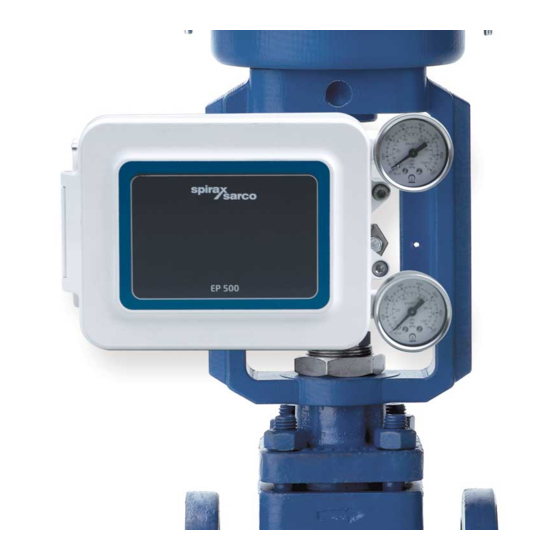
EP500
Advanced
ATEX Electropneumatic Positioner
Installation and Maintenance Instructions
2.
information
Technical
3. Installation
5. Maintenance
8. Approvals
© Copyright 2017
IM-P343-46 CTLS Issue 3
1
Printed in GB
Advertisement
Table of Contents

Related Manuals for Spirax Sarco EP500


Summary of Contents for Spirax Sarco EP500
- Page 1 IM-P343-46 3.568.5275.306 CTLS Issue 3 EP500 Advanced ATEX Electropneumatic Positioner Installation and Maintenance Instructions 1. Safety information information Technical 3. Installation 4. Commissioning 5. Maintenance 6. Spare parts 7. Fault finding 8. Approvals © Copyright 2017 IM-P343-46 CTLS Issue 3...
- Page 2 1. Safety information Safe operation of these products can only be guaranteed if they are properly i n s t a l l e d , c o m m i s s i o n e d , u s e d a n d m a i n t a i n e d by q u a l i f i e d p e r so n n e l (see Section 1.11) in compliance with the operating instructions.
- Page 3 1.16 Returning products Customers and stockists are reminded that under EC Health, Safety and Environment Law, when returning products to Spirax Sarco they must provide information on any hazards and the precautions to be taken due to contamination residues or mechanical damage which may present a health, safety or environmental risk.
- Page 4 2. General product information 2.1 Introduction The EP500 is a 2 wire loop powered positioner requiring a 4-20 mA control signal, and is designed for use with linear pneumatic valve actuators. The positioner compares the electrical signal from a controller with the actual valve position and varies a pneumatic output signal to the actuator accordingly.
- Page 5 2.3 Applications The EP500 can be used with any actuator that conforms to NAMUR, this includes all of the following Spirax Sarco pneumatic actuators: PN1000 and PN2000 series PNS3000 and PNS4000 series PN9000 series TN2000 series 2.4 Materials Part Material...
- Page 6 For best performance, set the air supply pressure to about 0.5 bar g above the pressure required to fully travel the actuator. Check all connections for leaks. Please note however that the EP500 bleeds air in normal operation at a rate of approximately 0.1 Nm³ / hour at 1.4 bar supply pressure.
- Page 7 4-20 mA Fig. 3 The barrier shall be chosen in accordance with intrinsic safety parameters declared for the EP500 positioner. Please refer to the technical sheet. IM-P343-46 CTLS Issue 3...
- Page 8 3.3 Mounting the positioner onto the actuator The EP500 can be attached onto any type of valve and actuator conforming to NAMUR standards. The unit can be attached in the traditional centered position (Figures 4 and 5) in line with the actuator central axis or side mounted (Figures 6 and 7) to enable the operator to view frontally the stem of the valve.
- Page 9 Step 2 Using the 2 off M6 pan head screws, securely attach the 'T' shaped sliding pin holder to the valve actuator coupling block (Figure 8). Fig. 8 Depending on the travel of the valve actuator and depending on the actuator yoke, apply a medium strength thread locker to the sliding pin and screw into the correct hole on the sliding pin holder and tighten.
- Page 10 Step 3 Attach the bracket to the actuator with the screw M8 x 20 with washers (Figure 10). Take care to insert the feedback pin in the slot of the feedback lever while you attach the positioner (Figure 11) Fig. 10 Fig.
- Page 11 Step 4 Air connections and electrical connections. Fig. 12 Connect the pneumatic output of the positioner to the actuator Warning For a perfect pneumatic seal, put the thread sealant (liquid Teflon) on the fitting thread and screw the connection with a torque: Minimum : 12 N m Maximum : 15 N m Connect the air supply...
- Page 12 Step 5 Fig. 14 After properly completing the wiring and before retightening the M50 Ex d cap, make sure that the M5 x 10 screw - Ex d locking cap is fully tightened, using a 4 mm allen key. Fig. 15 After manually screwing the cap Ex d M50 cap, loosen the Ex d locking cap M5 x 10 screw, using a 4 mm allen key, by exerting...
- Page 13 Step 6 Open the lid of the positioner. The positioner will be in this configuration: the spring of the SPAN disconnected. Fig. 16 Turn the ZERO dial (the green one), until the valve is opened at 50% Slightly loosen the M8 x 14 screw that is connecting the mounting bracket on to the actuator yoke.
- Page 14 Fig. 18 Correct placement Fig. 19 Incorrect placement Loosen the allen screw Rotate the lever to the Tighten the allen screw (black), (black), with a 4 mm key vertical position with a 4 mm key Fig. 20 4. Hook the spring to the respective pin on the SPAN IM-P343-46 CTLS Issue 3...
- Page 15 4. Commissioning 4.1 Set the valve action Firstly, with reference to Figure 21, determine the action that is relevant to your application. To change the slider turn the red gear until the slider is positioned into the correct half of the span arm. Please note that the arrow illustrates the stem movement direction when the input control signal increases.
- Page 16 4.2 Set sensitivity Xp regulation Fig. 22 We recommend not to change the Xp regulation until you familiarise with the product and with this regulation. To increase positioner sensitivity close the adjusting screw, to decrease sensitivity open the screw. Do not open the screw beyond the mechanical lock. Xp closed means the positioner is very reactive and consuming a small amount of air.
- Page 17 ZERO regulation Fig. 23 Feed the EP500 with a current input of 4 mA, turn the ZERO (green knob), till it reaches the value of the desired pressure and the valve opening reaches the starting position. Feed the EP500 with an input current of 20 mA, turn the SPAN (red knob), until it reaches the desired pressure and the valve is fully opened or reaches the desired opening percentage according to the application requirements.
- Page 18 4.3 Damping screw Fig. 24 The calibration of damping screw will be carried out during plant operation, it has the purpose of limiting, if necessary, the speed of the pneumatically operated valve: the reduction of the air flow to the servo motor may introduce delays in the positioning of the valve for which it is recommended for use only in the case of servomotors of small capacity and when there is a major tendency to cyclical swings.
- Page 19 5. Maintenance 5.1 Regular maintenance 1. Drain any build-up within the air supply filter set as impurities such as oil, water and dirt will cause inconsistent operation. 2 .Ensure air supply is at the correct pressure (see Section 3.3.2 and refer to the actuator TI). 3.
- Page 20 Always order spares by using the description in the column headed 'Available spares' and a description of the product. Example: 1 off Gauge 0 - 2 bar for a Spirax Sarco EP500 electropneumatic positioner. 1, 2, 3 1, 2, 3 Fig.
- Page 21 4. If the equipment is being returned under warranty, please indicate: Date of purchase ii. Original order number Please return all items to your local Spirax Sarco branch. Please ensure all items are suitably packed for transit (preferably in the original cartons). IM-P343-46 CTLS Issue 3...
- Page 22 7. Fault finding Output pressure too low or zero Cause Remedy a. No control signal a. Restore mA signal b. Low air supply pressure b. Verify actuator air pressure requirement c. Clogged or dirty sensitivity adjuster c. Clean adjuster see Section 5.2.1 d.
- Page 23 Actuator failing to fully open valve Cause Remedy a. Output pressure too low a. Refer to previous fault b. Incorrect travel adjustment b. Recalibrate see c. Valve / actuator coupling incorrect d. Reset (refer to valve / actuator IMI's) d. Actuator too small e.
- Page 24 8. Approvals IM-P343-46 CTLS Issue 3...
- Page 25 IM-P343-46 CTLS Issue 3...
- Page 26 IM-P343-46 CTLS Issue 3...
- Page 27 IM-P343-46 CTLS Issue 3...
- Page 28 IM-P343-46 CTLS Issue 3...
Need help?
Do you have a question about the EP500 and is the answer not in the manual?
Questions and answers