Advertisement
Table of Contents
IM-P343-16
3.568.5275.226
CH Issue 7 - 2016
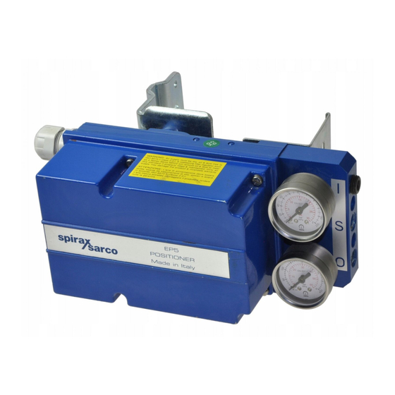
EP5 and ISP5 Series
Electropneumatic Positioners
Installation and Maintenance Instructions
Attention: Additional instructions are required when a ATEX
intrisically safety instrument ISP5 is used in an explosion risk area.
1. Safety information
2. Introduction
3. Installation
4. Commissioning
5. Maintenance
6. Spare parts
7. Fault finding
© Copyright 2016
E X P E R T I S E
S O L U T I O N S
S U S T A I N A B I L I T Y
Advertisement
Table of Contents


Need help?
Do you have a question about the EP5 Series and is the answer not in the manual?
Questions and answers