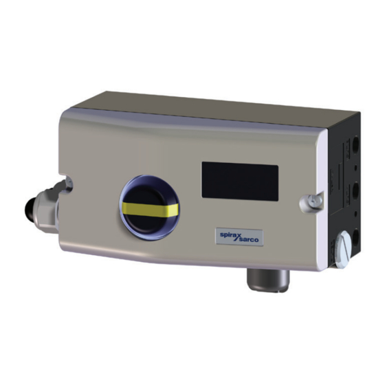
Spirax Sarco SP7-10 Quick Start Manual
Digital positioner
Hide thumbs
Also See for SP7-10:
- Manual (64 pages) ,
- Installation and maintenance instructions manual (48 pages) ,
- Installation and maintenance instructions (4 pages)
Table of Contents
Advertisement
Advertisement
Table of Contents

Summary of Contents for Spirax Sarco SP7-10
- Page 1 3440753/1 IM-P706-05 CTLS Issue 1 SP7-10, SP7-11 and SP7-12 Digital positioner Quick start guide Safety information Installation Approvals Declaration of conformity SP7-10, SP7-11 and SP7-12 Digital positioner © Copyright 2022 IM-P706-05 CTLS Issue 1...
-
Page 2: Safety Information
Throughout the document SP7-1* is written where the information is relevant to all versions; the SP7-10, SP7-11 and SP7-12. Where the information is specific it will be referenced as the version appropriate... -
Page 3: Installation
Tighten the screws so that they are hand tight Attach the follower guide (1) and clamp plates (2) with screws (4) and spring washers (3) to the actuator stem. Fig. 2 SP7-10, SP7-11 and SP7-12 Digital positioner IM-P706-05 CTLS Issue 1... - Page 4 4 fig. 3). 2.4 Mounting on a yoke Attach the mount bracket (2) with screw (4) and washer (3) to the yoke (1). Fig. 4 SP7-10, SP7-11 and SP7-12 Digital positioner IM-P706-05 CTLS Issue 1...
- Page 5 Recommended range for linear actuators: −28 to 28° Minimum angle: 25° Note After mounting, check whether the positioner is operating within the measuring range. SP7-10, SP7-11 and SP7-12 Digital positioner IM-P706-05 CTLS Issue 1...
- Page 6 Potentiometer lever Actuator bolts Valve stem Valve yoke Positioner Fig. 7 2.9 Actuator bolts on the Valve (rear view) Potentiometer lever Actuator bolts Valve stem Valve yoke Positioner Fig. 8 SP7-10, SP7-11 and SP7-12 Digital positioner IM-P706-05 CTLS Issue 1...
- Page 7 2. One of the threaded pins must be locked in place on the flat side of the feedback shaft. Fig. 9 2.11 Screwing the attachment bracket onto the positioner (1) Attachment bracket Fig. 10 SP7-10, SP7-11 and SP7-12 Digital positioner IM-P706-05 CTLS Issue 1...
-
Page 8: Electrical Connections
After mounting, check whether the operating range of the actuator matches the measuring range of the positioner, refer to measuring and operating ranges of the positioner on page 4. Fig. 11 2.13 Electrical connections Positioner SP7-10 Control Unit Electrical Connection Basic device Terminal Function/comments +11/−12 Analog input +81/−82... -
Page 9: Connection On The Device
The connecting terminals are delivered closed and must be unscrewed before inserting the wire. Strip the wires to approximately 6 mm (0.24 in). Connect the wires to the connecting terminals in line with the connection diagram. SP7-10, SP7-11 and SP7-12 Digital positioner IM-P706-05 CTLS Issue 1... -
Page 10: Pneumatic Connections
Free of oil, water and dust in accordance with DIN/ISO 8573-1. Pollution and oil content in accordance with Class 3:3:3 Do not exceed the maximum output pressure of the actuator *** Independent of supply pressure SP7-10, SP7-11 and SP7-12 Digital positioner IM-P706-05 CTLS Issue 1... -
Page 11: Standard Automatic Adjustment
Check mechanical mounting in accordance with Mechanical mounting on page 14 and repeat the standard automatic adjustment. * The zero position is determined automatically and saved during standard automatic adjustment, counter- clockwise (CTCLOCKW) for linear actuators and clockwise (CLOCKW) for rotary actuators. SP7-10, SP7-11 and SP7-12 Digital positioner IM-P706-05 CTLS Issue 1... -
Page 12: Declaration Of Conformity
Signed for and on behalf of: Spirax Sarco Ltd, (signature): (name, function): M Sadler Head of Engineering Steam Business Development (place and date of issue): Cheltenham SP7-10, SP7-11 and SP7-12 Digital positioner 2022-03-14 GNP237-EU-C/04 issue 1 (EN) Page 1/25 IM-P706-05 CTLS Issue 1...


Need help?
Do you have a question about the SP7-10 and is the answer not in the manual?
Questions and answers