Spirax Sarco SP7-10 Installation And Maintenance Instructions Manual
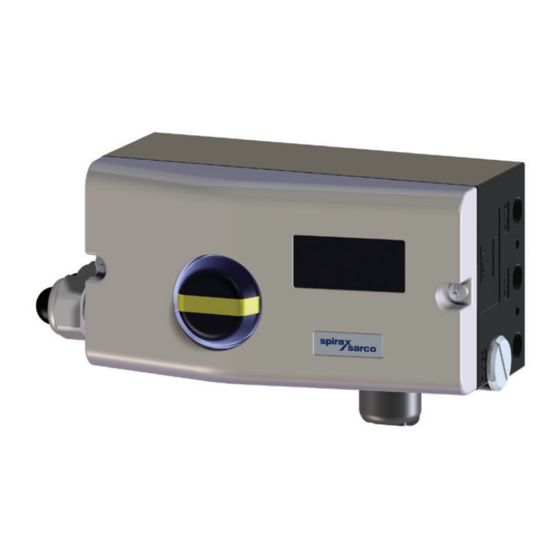
Digital positioner
Hide thumbs
Also See for SP7-10:
- Manual (64 pages) ,
- Quick start manual (13 pages) ,
- Installation and maintenance instructions (4 pages)
Table of Contents
Advertisement
Advertisement
Table of Contents

Related Manuals for Spirax Sarco SP7-10


Summary of Contents for Spirax Sarco SP7-10
- Page 1 3440750/1 IM-P706-02-US Issue 1 SP7-10 Digital positioner Installation and Maintenance Instructions Safety information General product information Installation Commissioning Operation Troubleshooting SP7-10 Digital positioner © Copyright 2021 IM-P706-02-US Issue 1 Printed in US...
- Page 2 Work(s) may not be used, sold, licensed, transferred, copied or reproduced in whole or in part or in any manner or form other than as expressly granted here without the prior written consent of Spirax-Sarco Limited. SP7-10 Digital positioner IM-P706-02-US Issue 1...
-
Page 3: Table Of Contents
4.7 Setting the mechanical limit switch with proximity switches 4.8 Setting the mechanical limit switch with 24 V micro-switches Operation 5.1 Parameterization of the device 5.2 HART Parameter Overview ® Troubleshooting 6.1 Error codes 6.2 Alarm codes 6.3 Message codes SP7-10 Digital positioner IM-P706-02-US Issue 1... -
Page 4: Safety Information
Consider: flammable materials, substances hazardous to health, extremes of temperature. 1.6 Hazardous environment around the product Consider: lack of oxygen (e.g. tanks, pits), dangerous gases, extremes of temperature, hot surfaces, fire hazard (e.g. during welding), excessive noise, moving machinery. SP7-10 Digital positioner IM-P706-02-US Issue 1... - Page 5 1.10 Tools and consumables Before starting work ensure that you have suitable tools and / or consumables available. Use only genuine Spirax Sarco replacement parts. 1.11 Protective clothing Consider whether you and / or others in the vicinity require any protective clothing to protect against the hazards of, for example, chemicals, high / low temperature, radiation, noise, falling objects, and dangers to eyes and face.
- Page 6 Customers and stockists are reminded that under EC Health, Safety and Environment Law, when returning products to Spirax Sarco they must provide information on any hazards and the precautions to be taken due to contamination residues or mechanical damage which may present a health, safety or environmental risk.
-
Page 7: General Product Information
The SP7-1 is an electronically configurable positioner with communication capabilities designed for mounting on pneumatic linear or rotary actuators. Fully automatic determination of the control parameters and adaptation to the positioner allow for considerable time savings as well as optimum control behavior. SP7-10 Digital positioner IM-P706-02-US Issue 1... -
Page 8: Installation
Fig. 3 that the ac tuator travel or rot ation angle for position f e e d b a c k i s i m p l e m e n t e d correctly. SP7-10 Digital positioner IM-P706-02-US Issue 1... - Page 9 Lever with follower pin 10 Screws (for mechanical stroke 11 Spring washers 10 to 35 mm [0.39 to 1.38 in] 12 Clamp plates 20 to 100 mm [0.79 to 3.94 in]) 13 Follower guide Washers Screws SP7-10 Digital positioner IM-P706-02-US Issue 1...
- Page 10 3.1.4 Attaching a follower guide to the actuator Fig. 5 Tighten the screws so that they are hand tight Attach the follower guide (1) and clamp plates (2) with screws (4) and spring washers (3) to the actuator stem. SP7-10 Digital positioner IM-P706-02-US Issue 1...
- Page 11 Align the mount bracket in the oblong hole to ensure that the operating range is symmetrical. Set the valve mid stroke and align the lever horizontal (item 4 fig. 7). Then tighten mounting bolt (item 4 fig. 7) (lever moves between the arrow marks item 4 fig. 8). SP7-10 Digital positioner IM-P706-02-US Issue 1...
- Page 12 Tighten the nuts so that they are hand-tight. Note Fig. 8 Adjust the height of the positioner on the cast iron yoke or columnar yoke until the lever is horizontal (based on a visual check) at half stroke of the valve. SP7-10 Digital positioner IM-P706-02-US Issue 1...
- Page 13 Select the chosen bolt position in the HMI menu in order to ensure optimum linearization. The default setting is actuator bolt on lever SP7-10 Digital positioner IM-P706-02-US Issue 1...
- Page 14 3.1.10 Actuator bolts on the lever (rear view) Potentiometer lever Actuator bolts Valve stem Valve yoke Positioner Fig. 10 3.1.11 Actuator bolts on the Valve (rear view) Potentiometer lever Actuator bolts Valve stem Valve yoke Positioner Fig. 11 SP7-10 Digital positioner IM-P706-02-US Issue 1...
- Page 15 Four M6 screws each (4), spring washers (3) and washers (2) to fasten the attachment bracket (6) to the positioner Four M5 screws (7), Spring washers (8) and washers (9) to fasten the attachment bracket to the actuator Required tools: Wrench, size 8/10 Allen key, size 3 SP7-10 Digital positioner IM-P706-02-US Issue 1...
- Page 16 Place the adapter in the proper position on the feedback shaft and fasten with threaded pins (2). One of the threaded pins must be locked in place on the flat side of the feedback shaft. SP7-10 Digital positioner IM-P706-02-US Issue 1...
- Page 17 Fig. 14 3.1.15 Screwing the positioner onto the actuator Note After mounting, check whether the operating range of the actuator matches the measuring range of the positioner, refer to General on page 14. Fig. 15 SP7-10 Digital positioner IM-P706-02-US Issue 1...
-
Page 18: Electrical Connections
The SP7-1 can be fitted either with proximity switches or micro-switches as limit switches. It is not possible to combine both variants. For the version SP7-1 Control Unit with SP7-1 Remote Sensor, the limit switches are located in the SP7-1 Remote Sensor. SP7-10 Digital positioner IM-P706-02-US Issue 1... - Page 19 9.7 V at 20 mA Impedance at 20 mA 485 Ω Note The SP7-1 Remote Sensor can be fitted either with proximity switches or micro-switches as limit switches. It is not possible to combine both variants. SP7-10 Digital positioner IM-P706-02-US Issue 1...
- Page 20 4 to 20 mA (split ranges can be parameterized) Signal range in the event of an error > 20 mA (alarm level) Supply voltage, two-wire technology 24 Vdc (11 to 30 Vdc) Characteristic curve rising or falling (configurable) Deviation < 1 % SP7-10 Digital positioner IM-P706-02-US Issue 1...
- Page 21 Terminals +41/−42, +51/−52 Supply voltage Maximum 24 V AC/DC Load rating Maximum 2 A Contact surface 10 µm Gold (AU) 3.2.14 Mechanical position indicator Indicator disc in enclosure cover linked with device feedback shaft. SP7-10 Digital positioner IM-P706-02-US Issue 1...
-
Page 22: Connection On The Device
The connecting terminals are delivered closed and must be unscrewed before inserting the wire. Strip the wires to approximately 6 mm (0.24 in). Connect the wires to the connecting terminals in line with the connection diagram. SP7-10 Digital positioner IM-P706-02-US Issue 1... - Page 23 0.14 to 1.0 mm (AWG26 to AWG18) Flexible with wire end sleeve no plastic sleeve 0.25 to 0.5 mm (AWG23 to AWG22) Flexible with wire end sleeve with plastic sleeve 0.25 to 0.5 mm (AWG23 to AWG22) SP7-10 Digital positioner IM-P706-02-US Issue 1...
-
Page 24: Connection On Device - Sp7-1 Control Unit With Sp7-1 Remote Sensor
Housing 2 (SP7-1 Remote Sensor) contains the position sensor and is suitable for mounting on linear or part-turn actuators. The following options may be installed, depending on the configuration ordered. Optical position indicator Mechanical feedback contacts designed as proximity switches or micro-switches. SP7-10 Digital positioner IM-P706-02-US Issue 1... - Page 25 If the SP7-1 Control Unit is fastened so that it is it non-conductive, the housing must be grounded (SP7-1 Control Unit and SP7-1 Remote Sensor housing with the same electric potential); otherwise control deviations could occur with regard to analog position feedback. Use wire end ferrules when connecting. SP7-10 Digital positioner IM-P706-02-US Issue 1...
-
Page 26: Connection On Device - Sp7-1 Control Unit For Remote Position Sensor
The SP7-1 Control Unit contains the electronics and pneumatics along with the following options (where applicable): Analog position feedback Digital position feedback Any position sensor (4 to 30 kΩ, with line break detection 4 to 18 kΩ) can be connected. SP7-10 Digital positioner IM-P706-02-US Issue 1... - Page 27 If the SP7-1 Control Unit is fastened such that it is it non-conductive, the housing must be grounded (SP7-1 Control Unit and remote position sensor housing with the same electric potential); otherwise control deviations could occur with regard to analog position feedback. Use wire end ferrules when connecting. SP7-10 Digital positioner IM-P706-02-US Issue 1...
- Page 28 The supply air pressure required to apply the actuating force must be adjusted in line with the output pressure in the actuator. The operating range of the positioner is between 1.4 to 6 bar (20 to 90 psi)***. *** 1.4 to 5.5 bar (20 to 80 psi) marine version SP7-10 Digital positioner IM-P706-02-US Issue 1...
-
Page 29: Pneumatic Connections - Air Supply
Free of oil, water and dust in accordance with DIN/ISO 8573-1. Pollution and oil content in accordance with Class 3:3:3 Do not exceed the maximum output pressure of the actuator *** Independent of supply pressure SP7-10 Digital positioner IM-P706-02-US Issue 1... -
Page 30: Commissioning
−28 to 28° Rotary actuators −57 to 57° Minimum angle 25° Perform standard automatic adjustment in accordance with standard automatic adjustment. Commissioning of the positioner is now complete, and the device is ready for operation. SP7-10 Digital positioner IM-P706-02-US Issue 1... -
Page 31: Operating Modes
Since self-optimization in operating mode 1.0 is subject to several factors during control operation with adaptation, incorrect adjustments could appear over an extended period. Positioning not active. *** For high-speed mode, press ARROW UP and ARROW DOWN simultaneously. SP7-10 Digital positioner IM-P706-02-US Issue 1... -
Page 32: Standard Automatic Adjustment
Check mechanical mounting in accordance with Mechanical Mounting on page 14 and repeat the standard automatic adjustment. * The zero position is determined automatically and saved during standard automatic adjustment, counter-clockwise (CTCLOCKW) for linear actuators and clockwise (CLOCKW) for rotary actuators. SP7-10 Digital positioner IM-P706-02-US Issue 1... -
Page 33: Sample Parameters
Press and hold down MODE and ENTER simultaneously, A dditionally quickly press and release ARROW UP 2×, The following is now shown in the display: Release MODE and ENTER. The following is now shown in the display: SP7-10 Digital positioner IM-P706-02-US Issue 1... -
Page 34: Setting The Option Modules
Attach the housing cover and screw it onto the housing. Tighten the screws so that they are hand- tight. Attach the symbol label to mark the minimum and maximum valve positions on the housing cover. Note: The labels are located on the inside of the housing cover. SP7-10 Digital positioner IM-P706-02-US Issue 1... -
Page 35: Setting The Mechanical Limit Switch With Proximity Switches
Fasten the lower washer with the special adjustment retainer and rotate the upper washer manually. Connect the microswitch. Attach the housing cover and screw it on to the housing. Tighten the screws so that they are hand-tight. SP7-10 Digital positioner IM-P706-02-US Issue 1... -
Page 36: Operation
Operating buttons for menu navigation 5.1.2 Value display with unit This 7-segment display with four digits indicates parameter values or parameter reference numbers. For values, the physical unit (°F, %, mA) is also displayed. SP7-10 Digital positioner IM-P706-02-US Issue 1... - Page 37 On the configuration level the active operating mode is deactivated. The I/P module is in neutral position. The control operation is inactive SP7-10 Digital positioner IM-P706-02-US Issue 1...
-
Page 38: Hart
5.2 HART Parameter Overview ® Operating level Parameter "EXIT" ENTER ENTER Configuration level MODE ENTER MODE Fig. 23 SP7-10 Digital positioner IM-P706-02-US Issue 1... - Page 39 Operating range, MAX_RGE 100.0 to 10.0 P3.1 range max. CLOCKWISE, P3.2 ZERO_POS Zero position Zero position CTCLOCKWISE CTCLOCKWISE Return to EXIT Return Function NV_SAVE P3.3 operating level Parameter description HART continued on next page ® SP7-10 Digital positioner IM-P706-02-US Issue 1...
- Page 40 0.0 to 45.0 P6.4 close Dead angle DANG_UP Dead angle 100% 55.0 to 100.0 100.0 P6.5 open BOLT_POS Bolt position Actuator position LEVER, STEM LEVER P6.6 Return to P6.7 EXIT Return Function NV_SAVE operating level SP7-10 Digital positioner IM-P706-02-US Issue 1...
- Page 41 4.0 to 20.0; 3.8 signal output to 4.0 bis 20.5 NV_SAVE clipping to 20.5 mA 3.8 to 20.5 mA range Return to EXIT Return Function P8.8 operating level Parameter description HART continued on next page ® SP7-10 Digital positioner IM-P706-02-US Issue 1...
- Page 42 5; 7 P11.4 Return to P11.5 EXIT Return Function NV_SAVE operating level *Activation by Spirax Sarco Service only Note For detailed information on the parameterization of the device, consult the associated configuration and parameterization instructions. SP7-10 Digital positioner IM-P706-02-US Issue 1...
-
Page 43: Troubleshooting
If the error still persists, made to restore the the device must be data. This compensates returned for repair to the for intermittent errors manufacturer. in the communication environment with the EEPROM. Error codes continued on next page SP7-10 Digital positioner IM-P706-02-US Issue 1... - Page 44 If the error can be the safe position. After reproduced and occurs approx. 5 seconds, the in the same position after positioner is automatically resetting, the device must reset. be returned for repair to the manufacturer. SP7-10 Digital positioner IM-P706-02-US Issue 1...
-
Page 45: Alarm Codes
PC with suitable software). ALARM 7 The specified limit value Reset the counter (only for the travel counter has possible via a connected been exceeded. PC with suitable software). SP7-10 Digital positioner IM-P706-02-US Issue 1... -
Page 46: Message Codes
SPR_ERR Actual spring action is different from the adjusted one. Time-out; parameter could not be determined within two minutes; TIMEOUT Auto-adjust was automatically stopped. SP7-10 Digital positioner IM-P706-02-US Issue 1... - Page 47 SP7-10 Digital positioner IM-P706-02-US Issue 1...
- Page 48 SP7-10 Digital positioner IM-P706-02-US Issue 1...
Need help?
Do you have a question about the SP7-10 and is the answer not in the manual?
Questions and answers