Table of Contents

Subscribe to Our Youtube Channel
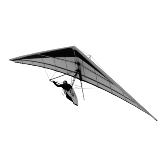
Related Manuals for Aeros FOX-18


Summary of Contents for Aeros FOX-18
- Page 1 HANG GLIDER FOX-18 OWNER / SERVICE MANUAL Manufactured by: Tel: (380 44) 4554120 AEROS Ltd. Fax: (380 44) 4554116 Post-Volynskaya St. 5 E-mail: INFO@AEROS.COM.UA Kiev 03061 Web-site: http://www.aeros.com.ua Ukraine November 2022...
- Page 2 AMENDMENTS Section Pages Date of Comments correction...
-
Page 3: Table Of Contents
12. Glider Tuning ……………………………………………………………………………………………. 18 13. Removing the Sail from the Airframe and Re-installing……………………………………………….20 14. Fox-18 Breakdown for Shipping Procedure in a 2.4 Meters Short Package………………………..22 15. Fox-18 Reassembly after Shipping Procedure from a 2.4 Meters Short Package…………………26 16. Maintenance.………………………………………………………………………………………………28 17. - Page 4 Please read and be sure you thoroughly understand this manual before flying the Fox-18. Be sure you are familiar with the glider and the contents of this manual before initial operation.
-
Page 5: Technical Information And Operating Limitations
The Fox 18 is not suitable for dual flight. Flight operation of the Fox-18 should be limited to non-aerobatic maneuvers; those in which the pitch angle will not exceed 30 degrees nose up or nose down from the horizon and the bank angle will not exceed 60 degrees. -
Page 6: Fox-18 Reassembly After Shipping Procedure
The sail mount screws on the front part of the leading edge tubes # 1 must be unscrewed, otherwise the excess sail tension will not allow tightening the sail. The sail mount screws have to be screwed back after you accomplish all steps in section “Fox-18 set-up procedure” from item 4.1 through item 4.8. -
Page 7: Fox-18 Set-Up Procedure
3.6 Zip up the glider bag zipper (fig. 3). Figure 3 4. FOX-18 SET-UP PROCEDURE 4.1 Lay the glider on the ground, with the bag zipper up and at right angles to the wind. 4.2 Undo the zipper and take the speed bar out of the pack. - Page 8 4.4 Flip the glider upright on the control bar. Try to set the speed bar on level ground. Remove the glider bag and all the Velcro sail ties. Take the batten bag with battens out of the pack. Do not remove the leading edge tip protection bags at this time (fig.
- Page 9 At the trailing edge on the top surface of the wing find the sweep (crossbar tensioning) wires pull handle webbing. Pull the sweep wires handle rearwards along the keel tube, checking that the sweep wires are not twisted. The king post will rise up when doing so. Attach the shackle of the sweep wires to the hook, which is placed on the keel tube (fig.
- Page 10 Aeros convention is that red marked battens go in the left wing and green marked battens in the right. Battens are numbered from the centre outwards, and the longest batten in a Fox-18 is designated as the "No.
-
Page 11: Preflight Procedure
(fig. 21). WARNING DO NOT FLY WITHOUT THE NOSECONE! Figure 21 For more information on Fox-18 set up procedure, see the video: https://www.youtube.com/watch?v=zfJfo0Q4Fu4 5. PREFLIGHT PROCEDURE Conduct a complete preflight inspection of the glider, checking all assemblies, which have not already been checked. - Page 12 Figure 24 Figure 25 Check that the sail mount strap is properly secured on the LE plastic cap (fig. 25). Figure 26 Along the trailing edge, left wing: Check that there are no tears in the sail material along the trailing edge. Check that all battens are properly secured.
- Page 13 Check the kingpost top for proper attachment of the bridles and condition of the top rear wire, carabiner and bridle wires. Along the trailing edge, right wing: Same as for the left wing. At the right tip: Same as for the left tip. Along the right leading edge: Same as for the left leading edge.
-
Page 14: Laying The Glider Down Flat
8. SPEED TO FLY The range of trim speed for the Fox-18 is 30 - 32 km/h (19-20 mph). The speed bar position in front of the pilots face corresponds to this range. The range of stall speed for the Fox-18 is 25 - 26 km/h (16-17 mph). The glider is stable at the beginning of stall. -
Page 15: Aerotowing
Be prepared to pull in once clear of the cart if necessary so as not to climb more quickly than the tug. Note that the bar pressure of the Fox-18 will be relatively high during the aerotowing. - Page 16 11.2 Remove the keel tube extension from the keel tube and support the glider under the keel tube with it. 11.3 Pull out the outboard sprogs, swing them towards the leading edge and fix with Velcro (fig. 33). Figure 33 11.4 Remove all top surface battens including the tip battens, except for the battens # 1.
- Page 17 Figure 37 Figure 38 11.11 Lift the nose batten string up, then pull it sideways and down, so that the nose batten tip lowered from the top of the keel tube (fig. 39). 11.12 Pull the sail out away from the keel until it is even on top and bottom. Roll the sail gently and carefully, parallel to the trailing edge of the front and then outboard portion of the sail (fig.
-
Page 18: Glider Tuning
If the battens tensioned too much, the handling will become harder. Make sure the batten tension on both wings is identical. All battens on the Fox-18 (except for the tip battens) are tensioned by lever batten tips. The desired batten tension can be easily adjusted by the threaded batten tip adjuster. -
Page 19: Removing The Sail From The Airframe And Re-Installing
On Fox-18, the hang loop fore and aft position is adjusted by repositioning the hang loops on the keel. Hang loop fore and aft position is adjusted by moving the holding belt with the Velcro (and with the hang loops inside) along the keel tube upper surface at the desired position. - Page 20 13.1.2 Spread the wings slightly. Remove all battens from the sail including the keel batten. Remove the screws that tether the nose part of the sail at the leading edge tubes (fig. 47). Undo the sail mount webbing Velcro and remove the sail mount webbing from the plastic end at the rear leading edge (fig. 48). Figure 47 Figure 48 Note: Reassemble the hardware removed in its place in original order so that it doesn’t get lost.
- Page 21 13.1.12 If you need to send the sail out for repair, remove the Mylar and the transverse battens. The Mylar is removed from the front end of the Mylar pocket. It helps to secure the opposite end of the sail to something solid, so that you can lay the leading edge out straight and pull the Mylar straight out of the pocket.
-
Page 22: Fox-18 Breakdown For Shipping Procedure In A 2.4 Meters Short Package
14. Fox-18 BREAKDOWN FOR SHIPPING PROCEDURE IN A 2.4 METERS SHORT PACKAGE The Fox-18 design allows for the glider transportation in a 2.4 meters short package. Please read and be sure you thoroughly understand this manual before braking down you glider in to a short package. - Page 23 14.3 Unbolt bottom and upper side wires from the crossbar and feed the upper side wire through the hole and out of the sail (fig. 54). Figure 54 Figure 55 14.4 Unbolt the upper front wire from the nose plate and feed it through the hole and out of the sail (fig. 55).
- Page 24 14.14 Detach the rear part of the keel tube and fold it along. Disconnect leading edge tubes and crossbar tubes. 14.15 Fold lower control frame fittings as shown on fig. 58. Roll up all wires as shown on fig. 58 and fig.
-
Page 25: Fox-18 Reassembly After Shipping Procedure From A 2.4 Meters Short Package
Figure 65 Figure 66 Fox-18 reassembling procedure from a 2.4 meters short package is reverse to its breakdown procedure. Please read written above manual and be sure you thoroughly understand it before reassembling your glider from a 2.4 meters short package. - Page 26 15.2 Check completeness of the frame parts and make sure they have no damage after transportation. Rotate the control frame around its apex backwards so, that the control frame lower fittings are directed aft. Connect the rear keel tube with the front keel tube. Figure 67 Figure 68 Figure 69...
- Page 27 side up; the slit edge is at the front and on the bottom. The easiest way to install the Mylar is to push it into the pocket using a long lofting batten attached to the end of the Mylar insert, which is first inserted in the pocket.
-
Page 28: Maintenance
Aeros directly. It is not always obvious which items require attention and which is not. Minor dents or dings in a non-critical location on an airframe tube may not require any repair or maintenance. On the other hand, a wire that has been kinked one time can fail very quickly after that, and should be replaced immediately. - Page 29 16.2.2 Anytime you have the sail off the frame, inspect all of the batten pockets and batten pocket terminations. 16.2.3 Replace bottom side wires and the hang loop. 16.3 SPECIAL CIRCUMSTANCES 16.3.1 Any time you suffer a crash or extremely hard landing you should have an “annual” inspection done on your glider to insure that you find all damaged parts.
-
Page 30: Transportation And Storage
Fox-18 Batten number Sail height above keel tube, mm 2 - 2 3 - 3 4 - 4 6 -6 If measured distances are less than those of written in the table above, the glider should not be flown until readjusted. -
Page 31: In Closing - A Few Words On Your Safety
- Your glider is delivered to you ready to fly. Do not make any adjustments, which are not described in this manual. - If you are in doubt about any aspect of your glider, you should consult your dealer or Aeros for advice. - Only fly after having attended a good school, recognized by your hang gliding federation.
Need help?
Do you have a question about the FOX-18 and is the answer not in the manual?
Questions and answers