
Related Manuals for Aeros COMBAT-C


Summary of Contents for Aeros COMBAT-C
- Page 1 HANG GLIDER COMBAT-C MANUAL OWNER / SERVICE Manufactured by: AEROS Ltd. Tel: (380 44) 4554120 Post-Volynskaya St. 5 Fax: (380 44) 4554116 Kiev 03061 E-mail: INFO@AEROS.COM.UA Ukraine http:// www.aeros.com.ua April 2020...
-
Page 3: Table Of Contents
Table of Contents Introduction..…………………………………………..………….…..…………………………………………….4 Technical information and operating limitations …....…..………………………………………….5 Combat-C reassembly after shipping procedure…....…..……………..………………………………6 Combat-C breakdown for shipping procedure..….…...…...…...…..……………………………… 7 Combat-C set-up procedure......…..…....……....…….……………………………...8 Preflight procedure…………………………….………….………….…………….………………………………12 Laying the glider down flat……………..……….….……………………….….……........14 Launching and flying the Combat-C....…........……..........15 Aerotowing ..………………………………………….…………………………………………………………….15 Using the VG system................……..........16 Using the movable hang point system…………………………………………………………………………...16... -
Page 4: Introduction
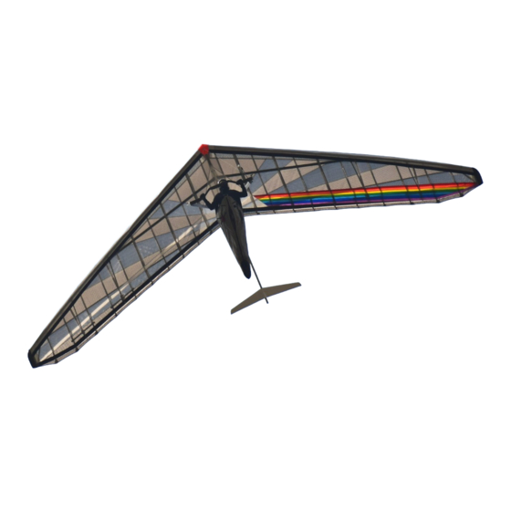
Combat C design is entirely based on the Combat GT hang glider. The Combat-C hang glider is an advanced product of Aeros Ltd. It is aimed at improvement of the modern competitive glider with very high performance combined with maximum safety and comfort. -
Page 5: Technical Information And Operating Limitations
TECHNICAL INFORMATION AND OPERATING LIMITATIONS The Combat-C has been designed for foot launched soaring flight. It has not been designed to be motorized, tethered, or towed. However it can be towed successfully using proper procedures. Flight operation of the Combat-C should be limited to non-aerobatic maneuvers; those in which the pitch angle will not exceed 30 degrees nose up or nose down from the horizon, and the bank angle will not exceed 60 degrees. -
Page 6: Combat-C Reassembly After Shipping Procedure
COMBAT-C REASSEMBLY AFTER SHIPPING PROCEDURE 1. With the glider in the bag (4 meters long) lay the glider on the ground. 2. Unzip the glider bag. Undo the Velcro straps. Remove the battens, the speedbar, the tail, the rear leading edge tubes, the main sprogs and the winglets from the glider bag. -
Page 7: Combat-C Breakdown For Shipping Procedure
Place Velcro ties around the glider. Put the speedbar, the tail and winglets between leading edges in the rear part of the glider. Put the glider bag back on and zip it up (Fig. 6). COMBAT-C BREAKDOWN FOR SHIPPING PROCEDURE This process will basically be the reverse of reassembling after breakdown for shipping. Before beginning, read through the section above on how to re-install the rear leading edges. -
Page 8: Combat-C Set-Up Procedure
3mm (1/8’’) from one batten to the other along the full length of the battens. Aeros convention is that green marked battens go in the right wing and red marked battens in the left wing. - Page 9 Figure 10 Figure 11 Install the lever batten tips into the hem of the trailing edge. At each batten, make sure the opening in the underside of the trailing edge hem is spread to accept the tab on the batten tip. Make sure the tab slides fully into the hem (Fig.10).
- Page 10 - pressing on the joint, push the partly folded batten towards the keel section, straightening the batten completely. When de-rigging the glider simply reverse the procedure written above. The adjustable tip lever batten is fixed to the LE # 3 tube with the threaded adjuster, giving a possibility to adjust the sail tension and to correct a light asymmetry in the glider with VG off, if necessary.
- Page 11 14. Install the nosecone taking care to align it so that it lies flat on the top and bottom of the sail (Fig.20). WARNING Don’t fly without the nosecone. Figure 18 15. Attach plastic winglets. Put front part of the winglet between the sail and the outer part of the leading edge tube (Fig.19).
-
Page 12: Preflight Procedure
If there is a slack between the keel and the tail we recommend wrap the keel tube with a tape or sticky Dacron as shown on the figure 25. WARNING It is prohibited to fly the Combat-C without the tail. 19. Do a complete preflight inspection of the glider (see the Section “Preflight procedure”). PREFLIGHT PROCEDURE Conduct a complete preflight inspection of the glider, checking all assemblies, which have not already been checked. - Page 13 - Open the main sprog access zipper and look inside, making sure that the crossbar / leading edge junction is assembled properly and safely secured with the nut, side wires are properly secured between the crossbar and the leading edge plate, that the thimbles are not cocked on the tang. Check that the sail is not caught on the crossbar end, or on any of the hardware Check the sprog hardware, and the sprog cable attachments at both ends of each sprog cable (Fig.26).
-
Page 14: Laying The Glider Down Flat
Check that the tail is properly installed. Along the trailing edge, right wing: Same as for the left wing. At the right tip: Same as for the left tip. Along the right leading edge: Same as for the left leading edge. Under the glider at the control bar: Sight down the down tubes, making sure that they are straight. -
Page 15: Launching And Flying The Combat-C
LAUNCHING AND FLYING THE COMBAT-C Before launching, hook in to the glider and do a careful hang check. We recommend that you hang as close to the base tube as possible - this will give you lighter control pressures and better control in both roll and pitch. -
Page 16: Using The Vg System
If your glider is equipped with the movable hang point system, refer to the Movable Hang Point System Manual for correct operation. LANDING THE COMBAT-C Under ideal conditions, landing approaches are best done so as to include a long straight final into the wind at a speed above best L/D speed. -
Page 17: Combat-C Breakdown
Figure 30 We wish you many happy landings! COMBAT-C BREAKDOWN Break down of the glider is the reverse of assembly. 1. Start with the VG set full loose. Remove the nosecone. Remove the tail. Remove any instruments. - Page 18 9. Detach the front wires at the nose plate. 10. Pull the sail out away from the keel until it is even on top and bottom. Roll the sail gently and carefully, parallel to the trailing edge of the front and then outboard portion of the sail. Try to roll the sail in such way that the leading edge portion remains as smooth as possible.
-
Page 19: Removing The Sail From The Airframe And Re-Installing
REMOVING THE SAIL FROM THE AIRFRAME AND RE-INSTALLING Many maintenance and repair procedures will require the removal of the sail from the frame. Please follow these instructions when removing and reinstalling the sail. Please read all the instructions for each operation before beginning. -
Page 20: Combat-C Stability Systems
Secure the sail mount tangs with the nuts at the nose plates after you accomplish all steps in section “Combat-C set-up procedure” from item 1 through item 8. 17. Do a very careful and complete preflight of the glider according to the normal preflight procedure as explained earlier in this manual. - Page 21 Aeros directly. It is not always obvious which items require attention and which may not. Minor dents or dings in a non-critical location on an airframe tube may not require any repair or maintenance.
- Page 22 Aeros Ltd or by the manufacture of the crossbeam. Conclusion about further possibility to use the crossbeam can be made only after loading the crossbeam and can be done by a representative of Aeros Ltd or by the manufacture of the crossbeam only.
-
Page 23: Glider Tuning
CG ADJUSTMENT You will find that the pitch trim of the Combat-C, as well as the basetube position at trim, changes with VG setting. At VG loose, the Combat-C will normally be trimmed very close to stall. The bar position at trim at VG loose will be relatively far out. - Page 24 3. Fully open the sprog access zipper. Place the worktop of the angle meter under the middle part of the sprog so that the entire worktop surface of the angle meter touches the sprog. The scale of the angle meter will show the sprog angle (Fig.38). Sprog angle Combat-C 12.7 Combat-C 13.5 Main sprogs, deg Outboard sprogs, deg...
- Page 25 To adjust the main sprog height: 1. Fully unzip the access zipper to gain access to the crossbar-LE junction (Fig.40). 2. Remove the pin from the sprog threaded adjuster at the front of the sprog. Remove the sprog rope pin from the crossbar.
-
Page 26: Transportation And Storage
NOTE The excess tensioned battens will worsen the handling. All battens on the Combat-C, except for the plug-on battens are tensioned by lever batten tips. The desired batten tension can be easily adjusted by the threaded lever batten tip adjuster (Fig. 42). -
Page 27: In Closing - A Few Words On Your Safety
Your glider is delivered to you ready to fly. Do not make any adjustments, which are not described in this manual. If you are in doubt about any aspect of your glider, you should consult your dealer or Aeros for advice. Only fly after having attended a good school, recognized by your hang gliding federation.
Need help?
Do you have a question about the COMBAT-C and is the answer not in the manual?
Questions and answers