Table of Contents
Advertisement
Quick Links
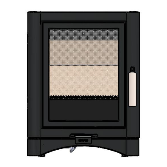
Installation & Operating Instructions
For The Evolution 5 Gas Stove MK2
Remote or Manual Control
Conventional, Top or Rear Flue, Natural Gas Stove
IT IS A REGULATION THAT THESE INSTRUCTIONS ARE HANDED TO THE
CUSTOMER AFTER THE INSTALLATION IS COMPLETE. IT IS ALSO THE
RESPONSIBILTY OF THE INSTALLATION ENGINEER TO ENSURE THE
CUSTOMER IS ABLE TO FULLY OPERATE THE APPLIANCE AND IS AWARE
OF ANY CLEANING OR MAINTENANCE REQUIRMENTS.
Please note: Gas installations MUST only be carried out by installers who
are Gas Safe registered.
Warning
- Appliance should not be used if the glass in the door is
cracked, damaged or broken.
This product is not suitable for primary heating purposes.
Chimney closure plates are not supplied
200759_2 TB Jan 2021
Advertisement
Table of Contents

Subscribe to Our Youtube Channel
Related Manuals for Broseley Evolution 5 MK2


Summary of Contents for Broseley Evolution 5 MK2
- Page 1 Installation & Operating Instructions For The Evolution 5 Gas Stove MK2 Remote or Manual Control Conventional, Top or Rear Flue, Natural Gas Stove IT IS A REGULATION THAT THESE INSTRUCTIONS ARE HANDED TO THE CUSTOMER AFTER THE INSTALLATION IS COMPLETE. IT IS ALSO THE RESPONSIBILTY OF THE INSTALLATION ENGINEER TO ENSURE THE CUSTOMER IS ABLE TO FULLY OPERATE THE APPLIANCE AND IS AWARE OF ANY CLEANING OR MAINTENANCE REQUIRMENTS.
-
Page 2: Table Of Contents
Contents Introduction Packing List Specification Dimensions Hearth Requirements Chimney Requirements Assembly Base Skirtings Burner Installation Mica Board Installation Connecting the TTB Sensor Ceramics Index 11 - 12 Positioning the logs Gas Connection & Pressure Testing Spillage Testing Operating the Stove Slide Control Version Operating the Stove Remote Control Version with Display 17 - 25 Maintenance / Cleaning / Curing the Paint... -
Page 3: Introduction
Introduction THANK YOU FOR PURCHASING A BROSELEY GAS STOVE Broseley Fires Ltd was founded as an appliance and design development and manufacturing company in 1975. Since then we have built up an enviable reputation for the quality, reliability and fuel efficiency of our stoves. -
Page 4: Specification
Specification Heat Input (Gross) 5.7kW Gas Category Supply Pressure 20 mbar Gas Rate 0.538 m Injector Type Stamped E5 125mm (5”) Flue diameter Country of destination GB, IE Efficiency Class Class 1 Nominal Output 4.3kW 130 mg/kWh (GCV) Please note this product is designed to only use natural gas G20. Dimensions WEIGHT 90 Kg All dimensions are in millimetres. -
Page 5: Hearth Requirements
Hearth Requirements The appliance needs to be located onto a solid non-combustible hearth with a minimum thickness of 12mm. The hearth must be capable of withstanding the weight of the appliance. NB Side measurements taken from the Lid of the stove (Dimension E on page 4): Rear measurement taken from the dilution box Ensure all minimum clearances to combustible materials are complied with as below:... -
Page 6: Chimney Requirements
Chimney Requirements Please note Broseley Fires do not provide flue pipes, closure plates or any other associated accessory. Top or Rear Flue Outlet The stove must be installed in accordance with current gas and buildings regulations BS5871: Part1. The appliance can be installed in any adequate area suitable for solid fuel fires and stoves. -
Page 7: Base Skirtings
Assembly – Base Skirting To make the gas supply connection (and also to replace batteries) on the stove you will first need to remove the base skirting’s. There are three skirting’s in total (one either side and one at the front). The side skirting’s are held in place by a key slot and a magnet, to remove simply slide the skirting away from you (towards the back of the stove) and pull free. -
Page 8: Burner Installation
Assembly - Burner Installation The burner will come pre-fitted, however please ensure all components are present and fitted as per the information below to ensure nothing has moved (or become damaged) in transit. You will need a 10mm socket for the burner and allen keys for the door when fitting / replacing these items. -
Page 9: Mica Board Installation
Assembly – Mica Board Installation As with the burner, the Mica boards will be pre-fitted into the stove. The information below will assist with the removal/re- installation should they need to be removed for maintenance purposes. First fit the rear mica board in front of the burner bracket as shown opposite Rest the top mica board (2) onto the rear, whilst holding the top mica in position, insert... -
Page 10: Connecting The Ttb Sensor
Assembly - Fitting Pilot to Valve and TTB sensor MANUAL VERSION With the burner installed, thread the 2 x TTB wires from the pilot / thermocouple to the rear of the stove. Attach the two spade connections to the TTB which is fitted to the bracket shown in Fig 1. -
Page 11: Ceramics Index
Assembly – Ceramics Index Ceramic Index 1 of 2 Main Fuel Bed Location Points 200759_2 Issue 3... - Page 12 Assembly – Ceramics Index Ceramic Index 2 of 2 Front Log Right hand log with split Rear Log Final Assembly 200759_2 Issue 3...
-
Page 13: Positioning The Logs
Broseley Fires will not be liable for any associated costs. 1: Place the main fuel bed onto the base plate... -
Page 14: Gas Connection & Pressure Testing
If the gas pressure is not as per above it will be the sole responsibility of the fitter to rectify and Broseley Fires will not be liable for any associated costs. -
Page 15: Spillage Testing
Spillage Testing A Spillage Test MUST be carried out before the installed fire is left with the customer. Carry out the test by first closing all doors and windows in the room containing the fire. Ensure that the fire is burning at full rate for a minimum of 10-15 minutes. Using a lighted smoke match, run it along under the rear edge of the stove. -
Page 16: Operating The Stove Slide Control Version
Operating the Stove - Manual Control Version It is important to read these instructions thoroughly before lighting the stove. The control for ignition, low and high setting is located on the front of the stove, the indicators in the control shows the burner position i.e. ignition, low, high or off The pilot light is located at the front left corner of the fuel bed. -
Page 17: Operating The Stove Remote Control Version With Display
Operating the Stove - Remote Control Version Quick start user instructions This control is situated on the lower right hand side of your fire. The drawing below shows the main features of the control. The control requires 3 AA size alkaline batteries to be inserted under the battery compartment cover. - Page 18 Operating the Stove - Remote Control Version Handset Ensure the power isolator switch on the front corner of Fire Control is in the on position I. NOTE: For safety reasons a button must be pressed and released for the command to be recognized.
- Page 19 Operating the Stove - Remote Control Version Operating instruction The handset comes already paired to work with the fire and the time set etc. Please read these instructions carefully and watch the instructional YouTube video through your internet web browser if necessary. Do not try pairing the handset thinking that it is not paired it is more likely the handset is not being pressed correctly.
- Page 20 Operating the Stove - Remote Control Version 3) Setting the time Should you have to set the time or change the time you need to enter the SETUP menu. Hold the handset to unlock the keypad and keep held throughout the following steps, (if you release too soon the menu will exit and you will have to start again).
- Page 21 Operating the Stove - Remote Control Version Setting the temperature display to Celsius or Fahrenheit Press and release the + or - button to toggle between C and F. When the display shows the desired symbol, press and releases the “SET”...
- Page 22 Operating the Stove - Remote Control Version Other Modes than Manual mode Depending upon the model of fire, your handset maybe enabled to have some automatic features, namely, Thermostat mode, timed thermostat mode and snooze mode. Snooze mode can be selected to work with in conjunction with either manual or thermostatic modes.
- Page 23 Operating the Stove - Remote Control Version Pairing Gas control with handset after handset has been made free to pair as above operation: • Ensure all the batteries are fitted correctly and with the power isolator slide switch on the TESC Fire control put in the “I” position). •...
- Page 24 Operating the Stove - Remote Control Version Snooze mode in Thermostatic mode The same thing as above can be done before or during a thermostatic mode operation (see below). Thermostatic mode The handset has within it a thermostat sensor and this can be set so the fire will heat the room to match the temperature set in the handset.
- Page 25 Operating the Stove - Remote Control Version Paging the handset If you have misplaced the handset you can page it by pressing the + button only on the fire control for around 5 seconds. The handset will flash and make a noise to help you to locate it.
-
Page 26: Maintenance / Cleaning / Curing The Paint
Maintaining the Stove Important Note: Should the glass door become broken or damaged in any way, turn your stove off and do not attempt to re-light it. Contact your dealer for a replacement to be fitted before relighting the appliance. The glass used in this appliance is a ceramic type glass suitable for operation up to 750 degrees do not use any other types of glass in this appliance. -
Page 27: Trouble-Shooting / Servicing
Trouble-shooting The gas pilot will not ignite or stay lit • Ensure the gas is turned on at the appliance and the meter / cylinder. • Check for blockages (especially after the pressure test point connection). • Is there a strong spark being generated, If not firstly check that the spade connection is push fully into the pilot assembly. - Page 28 Servicing Instructions Servicing should be carried out annually by a qualified installation gas safe engineer. • To open the door, remove the screw from above the handle to allow the door to open (Long allen key supplied). • Remove the logs and clean any dust and debris from the top of the burner unit and the inside of the stove.
-
Page 29: Commissioning Form
Commissioning Form THIS SECTION MUST BE COMPLETED AND SIGNED BY THE INSTALLATION ENGINEER PLEASE LEAVE WITH THE CUSTOMER AND THE APPLIANCE. Size of Governor setting: ___________ Length and size of gas supply: __________ Meter pressure Fire only on: ________________ Meter pressure with all other appliances on: __________________ Burner pressure Fire only on: _______________ Burner pressure with all other appliances on: __________________ Gas rate - Natural Gas - Time for 1 cubic foot in seconds: ___________... -
Page 30: Guarantee
The rights given in this guarantee are limited to the UK mainland and are in addition to any to which you may have a statutory entitlement. Please retain your purchase receipt. We will need to see this in the event of a claim under warranty. Broseley Fires LTD 19-34 Bedesway, Bede Industrial Estate, Jarrow, Tyne and Wear, NE32 3BE. -
Page 31: Energy Efficiency Rating
Energy Efficiency Rating Top Flue Option Rear Flue Option 200759_2 Issue 3... - Page 32 (shown in the tables above). This product MUST be installed by a Gas Safe Registered Installer. Full details are provided in this manual. Broseley Fires Ltd, 19-34 Bedesway, Bede Industrial Estate, Jarrow, Tyne and Wear, NE32 3BE. 200759_2 Issue 3...
Need help?
Do you have a question about the Evolution 5 MK2 and is the answer not in the manual?
Questions and answers