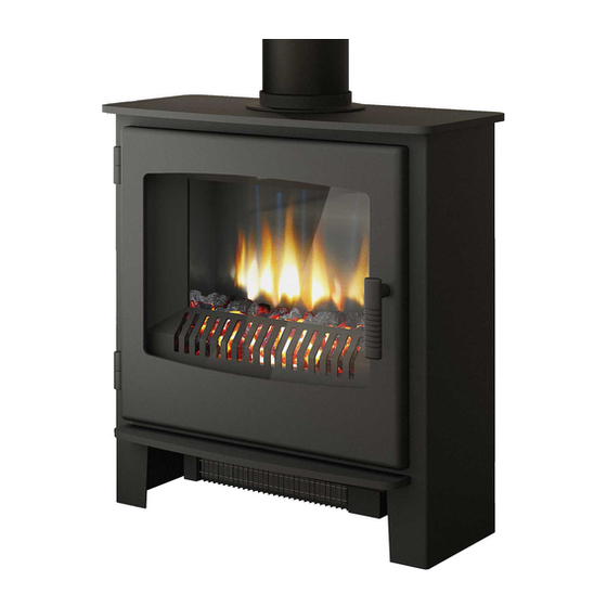
Broseley IGNITE 5 Installation & Operating Instructions Manual
Lpg q5 stoves.
manual control
conventional, top or rear flue, lpg gas stove
Hide thumbs
Also See for IGNITE 5:
- Installation & operating instructions manual (26 pages) ,
- Installation & operating instructions manual (32 pages)
Table of Contents
Advertisement
Installation & Operating Instructions
For LPG Q5 Stoves
IGNITE 5 GAS STOVE – (CD1)
HEREFORD 5 GAS STOVE – (CD2)
DESIRE 5 GAS STOVE – (SD1)
Manual Control
Conventional, Top or Rear Flue, LPG Gas Stove
END
PLEASE LEAVE THESE INSTRUCTIONS WITH THE
USER
Please note: Gas installations MUST only be carried out by installers who
are Gas Safe registered.
Warning
- Appliance should not be used if the glass in the door is
cracked, damaged or broken.
200768_1
1
Advertisement
Table of Contents

Related Manuals for Broseley IGNITE 5


Summary of Contents for Broseley IGNITE 5
- Page 1 Installation & Operating Instructions For LPG Q5 Stoves IGNITE 5 GAS STOVE – (CD1) HEREFORD 5 GAS STOVE – (CD2) DESIRE 5 GAS STOVE – (SD1) Manual Control Conventional, Top or Rear Flue, LPG Gas Stove PLEASE LEAVE THESE INSTRUCTIONS WITH THE...
-
Page 2: Table Of Contents
Contents Introduction Packing List Specification & Dimensions Hearth Requirements Chimney Requirements Assembly Burner Installation Mica Board Installation Connecting the TTB Sensor Ceramics Index Positioning the logs / Fitting the Decorative Log Retainer 11-13 Gas Connection & Pressure Testing Spillage Testing Maintenance Operating the Stove Cleaning the Stove / Curing the Paint... -
Page 3: Introduction
Introduction THANK YOU FOR PURCHASING A BROSELEY GAS STOVE Broseley Fires Ltd, a family run company, was founded as an appliance and design development company in 1975. Since then we have built up an enviable reputation for the quality, reliability and fuel efficiency of our stoves. -
Page 4: Specification & Dimensions
Specification Heat Input (Gross) 5.0kW Gas Category Supply Pressure 37 mbar Gas Rate 0.181 m Injector Size 7 x 0.45mm (L5) Flue diameter 125mm (5”) Country of destination GB, IE Efficiency Class Class 2 Nominal Output 3.5kW NOx Class 4 Top Flue, 5 Rear Flue Please note this product is designed to only use LPG Gas G31 Propane. -
Page 5: Hearth Requirements
Hearth Requirements The appliance needs to be located onto a solid non-combustible hearth with a minimum thickness of 12mm. The hearth must be capable of withstanding the weight of the appliance. NB Side measurements taken from the Lid of the stove (Dimension E on page 4): Rear measurement taken from the dilution box Ensure all minimum clearances to combustible materials are complied with as below:... -
Page 6: Chimney Requirements
Chimney Requirements Please note Broseley Fires do not provide flue pipes, closure plates or any other associated accessory. Top or Rear Flue Outlet The stove must be installed in accordance with current gas and buildings regulations BS5871: Part1. The appliance can be installed in any adequate area suitable for solid fuel fires and stoves. -
Page 7: Burner Installation
Assembly - Burner Installation The burner will come pre-fitted, however please ensure all components are present and fitted as per the information below prior to commencing installation. You will need a pozi drive screwdriver when fitting/replacing these items. 1) Remove the stove body from its packaging and stand it in position. 2) To open the door, remove the handle by rotating it anti-clockwise until it clears the thread. -
Page 8: Mica Board Installation
Assembly – Mica Boards First fit the rear mica board as Now fit one of the side mica boards shown above. ensuring that the board is snug between the front of the stove and the rear mica Next rest the top mica board onto Finally fit the reaming side mica the side board (this board will board and allow the top board to... -
Page 9: Connecting The Ttb Sensor
Assembly - Fitting TTB sensor With the burner installed, thread the TTB connection cable from the interrupter to the TTB sensor (mounted on the rear panel of the stove). Thermo Couple Connection Cable TTB sensor (located just below the rear Interrupter flue outlet). -
Page 10: Ceramics Index
Broseley Fires Ltd accepts no responsibility for any injury sustained whilst handling hot ceramics. Ceramics which are placed other than in accordance with these instructions will be the sole responsibility of the fitter to rectify, and Broseley Fires will not be liable for any associated costs. -
Page 11: Positioning The Logs / Fitting The Decorative Log Retainer
Assembly – Positioning of the Logs STEP 1 – Place the main ceramic base in position as below Using the 2 off M5 C/Sunk Bolts provided, locate the decorative trim behind the stove opening as shown and secure in position. Although it is possible to position all of the ceramics first, we recommend fitting the log retainer at this point as it will make things easier. - Page 12 Assembly – Positioning of the Logs STEP 2 – Place the front log with the two cut outs in on the front of the main base so it touches the rear of the log retainer STEP 3 – Place the large rear log in position across the rear of the base as below 200768_1...
- Page 13 Assembly - Positioning the Logs STEP 4 – The final positioned across centre, ensure the right hand part of the log (as you look at it) is touching both the front right hand side of the main base so it tilted back over.
-
Page 14: Gas Connection & Pressure Testing
If the gas pressure is not as per above it will be the sole responsibility of the fitter to rectify and Broseley Fires will not be liable for any associated costs. -
Page 15: Spillage Testing
Spillage Testing A Spillage Test MUST be carried out before the installed stove is left with the customer. Carry out the test by first closing all doors and windows in the room containing the fire. Ensure that the fire is burning at full rate for a minimum of 10-15 minutes. Using a lighted smoke match, run it along under the rear edge of the stove. -
Page 16: Maintenance
Maintenance Door adjustment In the case of the door rope not providing an adequate seal to the room, products of combustion may enter the room (see warning notes), to ensure an adequate seal the door may need to be periodically adjusted as the rope seal wears with use. Hinge Adjustment (seal on Left hand side is not compressed): DESIRE (SD1) AND IGNITE (CD1) MODELS ONLY ... -
Page 17: Operating The Stove
Operating the Stove It is important to read these instructions thoroughly before lighting the stove. The gas stove operates with a traditional permanent pilot light. The knob for ignition and power control are located on the lower right hand side of the stove, the indicator in the plate shows the knob position (Marked on knob) The pilot light is located at the front left corner of the main ceramic. -
Page 18: Cleaning The Stove / Curing The Paint
Cleaning the Stove / Curing the Paint Important Note: Should the glass door become broken or damaged in any way, turn your stove off and do not attempt to re-light it. Contact your dealer for a replacement to be fitted before relighting the appliance. -
Page 19: Trouble-Shooting
Trouble-shooting The gas pilot will not ignite or stay lit Ensure the gas is turned on at the appliance and the meter / cylinder. Is there a strong spark being generated, check connections if not. The pilot gas button must be held in for at least 20 seconds once the pilot is established to ensure the safety thermocouple is heated sufficiently. - Page 20 Trouble-shooting The main burner does not seem to burn correctly or will not stay alight Ensure gas pressures and flow rates are correct. Test with all ceramics removed Confirm that the flame pattern is even across the surface of the burner by removing all of the ceramics.
-
Page 21: Servicing
Servicing Instructions Servicing should be carried out annually by a qualified installation gas safe engineer. To open the door, remove the handle by rotating it anti-clockwise until it clears the thread. The handle acts like a nut on a thread and once removed will allow the door to open fully. -
Page 22: Guarantee
THIS SECTION MUST BE COMPLETED AND SIGNED BY THE INSTALLATION ENGINEER PLEASE LEAVE WITH THE CUSTOMER AND THE APPLIANCE. Size of Governor setting: (i.e.) Propane Gas 37mbar. Length and size of gas supply: _______________ Meter pressure Stove only on: ________________ Meter pressure with all other appliances on: __________________ Burner pressure Stove only on: _______________ Burner pressure with all other appliances on: __________________... - Page 23 Should you wish to claim under the warranty, please contact the supplier / dealer from whom you purchased the appliance. Do not claim directly to Broseley Fires, or Be Modern, as they are unable to process any direct claim from an end user.
Need help?
Do you have a question about the IGNITE 5 and is the answer not in the manual?
Questions and answers