Table of Contents
Advertisement
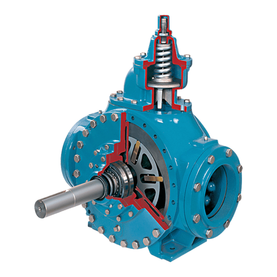
BLACKMER POWER PUMPS
INSTALLATION OPERATION AND MAINTENANCE INSTRUCTIONS
MODELS: HXL6G, HXL8G, HXLJ8G, HXL10E
TABLE OF CONTENTS
Technical Data ........................................................... 2
Initial Pump Start Up Information................................ 2
Pre-Installation Cleaning ............................................ 3
Location and Piping .................................................... 3
Pump Mounting .......................................................... 3
Coupling Alignment .................................................... 4
Pump Rotation ........................................................... 4
To Change Pump Rotation ......................................... 4
Check Valves ............................................................. 4
Manual Bypass Valves ............................................... 4
Pre-Start Up Check List .............................................. 5
Start Up Procedures ................................................... 5
Running the Pump in Reverse Rotation ..................... 5
Flushing the Pump ..................................................... 6
Pump Relief Valve ...................................................... 6
Relief Valve Setting and Adjustment .......................... 6
Torque Table .............................................................. 7
Scheduled Maintenance ............................................. 7
Strainers ............................................................... 7
Lubrication ............................................................ 7
Vane Replacement ..................................................... 8
Pump Disassembly (HXL6 and HXLJ8) ...................... 9
Pump Assembly (HXL6 and HXLJ8) ......................... 9
Pump Disassembly (HXL8 and HXL10) ................... 11
Pump Assembly (HXL8 and HXL10) ....................... 12
TROUBLE SHOOTING....................................................... 14
Numbers in parentheses following individual parts indicate
reference numbers on the Blackmer Parts List for the pump
being serviced.
PUMP PARTS LISTS
HXL6
HXL8, HXLJ8
102-A01
Blackmer pump manuals and parts lists may be obtained
from
Blackmer's
website (www.blackmer.com)
contacting Blackmer Customer Service.
HXL10
102-A02
102-A04
This is a SAFETY ALERT SYMBOL.
When you see this symbol on the product, or in the
manual, look for one of the following signal words and be
alert to the potential for personal injury, death or major
Warns of hazards that WILL cause serious personal
injury, death or major property damage.
Page
Warns of hazards that CAN cause serious personal
injury, death or major property damage.
Warns of hazards that CAN cause personal injury
Indicates special instructions which are very
important and must be followed.
Blackmer Power Pumps MUST only be installed in
systems, which have been designed by qualified
engineering personnel. The system MUST conform to all
applicable local and national regulations and safety
standards.
This manual is intended to assist in the installation and
operation of Blackmer Power pumps, and MUST be kept
with the pump.
Pump service shall be performed by qualified technicians
ONLY. Service shall conform to all applicable local and
national regulations and safety standards.
Thoroughly review this manual, all instructions and
hazard warnings, BEFORE performing any work on the
pump.
Maintain ALL system and pump operation and hazard
warning decals.
or
by
960229
INSTRUCTIONS NO. 102-A00
Section
102
Effective
Jun 2020
Replaces
Jan 2014
SAFETY DATA
property damage
or property damage.
NOTICE:
NOTICE:
Advertisement
Table of Contents

Subscribe to Our Youtube Channel
Related Manuals for BLACKMER HXL6G


Summary of Contents for BLACKMER HXL6G
-
Page 1: Table Of Contents
TROUBLE SHOOTING............14 hazard warnings, BEFORE performing any work on the pump. Numbers in parentheses following individual parts indicate reference numbers on the Blackmer Parts List for the pump Maintain ALL system and pump operation and hazard being serviced. warning decals. -
Page 2: Pump Data
If replacement parts are needed, or if information pertaining to the pump is required, this data must be furnished to a Blackmer representative. TECHNICAL DATA *... -
Page 3: Installation
INSTALLATION NOTICE: ALL piping and fittings MUST be properly supported to Blackmer power pumps must only be installed in prevent any piping loads from being placed on the pump. systems designed by qualified engineering personnel. 10. Check alignment of pipes to pump to avoid strains which System design must conform with all applicable might later cause misalignment. -
Page 4: Coupling Alignment
INSTALLATION COUPLING ALIGNMENT TO CHANGE PUMP ROTATION The pump must be directly coupled to a gear and/or driver The vanes (14) must be reversed so that the relief grooves with a flexible coupling. Verify coupling alignment after face in the direction of rotation. On HXL10, HXL8 and HXLJ8 installation of new or rebuilt pumps. -
Page 5: Operation
OPERATION START UP PROCEDURES NOTICE: Operation without guards in place can Consult the "General Pump Troubleshooting" section of this manual if difficulties during start up are experienced. cause serious personal injury, major property damage, or death. Start the motor. Priming should occur within one minute. Do not operate Check the inlet and discharge pressure gauges to ensure without guard... -
Page 6: Flushing The Pump
Replace the valve cap. NOTICE: After flushing the pump some residual fluid will remain in Refer to the individual Blackmer pump parts lists for various the pump and piping. spring pressure ranges. Unless specified otherwise, pumps NOTICE:... -
Page 7: Maintenance
MAINTENANCE TORQUE TABLE Capscrew Torque Values Bearing Failure to disconnect and lockout Head Cover electrical power before attempting 100 lbs-ft. 50 lbs-ft. maintenance can cause shock, burns or HXL6 (136 Nm) (68 Nm) death Hazardous voltage. 178 lbs-ft. 50 lbs-ft. 50 lbs-ft. -
Page 8: Vane Replacement
MAINTENANCE VANE REPLACEMENT NOTICE: Vanes may be replaced with the pump in the upright Maintenance shall be performed by qualified technicians position. only, following the appropriate procedures and warnings as presented in manual. Flush the pump per instructions in this manual. Drain and relieve pressure from the pump and system as required. -
Page 9: Pump Disassembly (Hxl6 And Hxlj8)
MAINTENANCE: HXL6 and HXLJ8 MODELS PUMP DISASSEMBLY – HXL6 and HXLJ8 Remove the top vane then rotate the shaft by hand to bring the next vane to the top until all the vanes have NOTICE: been removed. If the vanes are swollen or jammed in Follow all hazard warnings and instructions provided in their slots , the rotor-shaft must be removed as described the “Maintenance”... - Page 10 MAINTENANCE: HXL6 and HXLJ8 MODELS Remove the vanes (14) and push rods (77) from the rotor Set the pump upright. and shaft assembly. Inspect for wear and damage, and 10. Remove the outboard head and disc temporarily replace as follows: attached earlier.
-
Page 11: Pump Disassembly (Hxl8 And Hxl10)
MAINTENANCE: HXL8 and HXL10 MODELS PUMP DISASSEMBLY – HXL8 and HXL10 Remove the capscrews from the hub (21A) and slide the hub assembly off the shaft. The bearing, stationary seat and stationary O-ring of the mechanical seal (153B, NOTICE: 153D) will come off with the hub. Follow all hazard warnings and instructions provided in Pull the bearing (24) from the housing in the hub. -
Page 12: Pump Assembly (Hxl8 And Hxl10)
MAINTENANCE: HXL8 and HXL10 MODELS PUMP ASSEMBLY – HXL8 and HXL10 HXL10: Using a hoist, place the disc (71) on the head with the counterbored screw holes facing out. The word Before reassembling the pump, inspect all component “INTAKE” on the disc should be positioned so that it parts for wear or damage, and replace as required. - Page 13 MAINTENANCE: HXL8 and HXL10 MODELS 15. LOCKNUT ADJUSTMENT It is important that the bearing locknuts (24A) and lockwashers (24B) be installed and adjusted properly. Overtightened locknuts can cause bearing failure or a Operation without guards in place can broken lockwasher tang. Loose locknuts will allow the cause serious personal injury, major rotor to shift against the discs, causing wear.
-
Page 14: Troubleshooting
TROUBLESHOOTING NOTICE: Maintenance shall be performed by qualified technicians only, following the appropriate procedures and warnings as presented in this manual. SYMPTOM PROBABLE CAUSE Pump not wetted. Worn vanes. Suction valve closed. Internal control valve closed. Air leaks in the suction line. Strainer clogged. - Page 15 TROUBLESHOOTING NOTICE: Maintenance shall be performed by qualified technicians only, following the appropriate procedures and warnings as presented in this manual. SYMPTOM PROBABLE CAUSE Foreign objects entering the pump. Running the pump dry for extended periods of time. Cavitation. Viscosity too high for the vanes and /or the pump speed. Incompatibility with the liquids pumped.
- Page 16 1809 Century Avenue, Grand Rapids, Michigan 49503-1530 U.S.A. Telephone: (616) 241-1611 • Fax: (616) 241-3752 E-mail: blackmer @blackmer.com • Internet Address: www .blackmer.com 102-A00 page 16/16...
Need help?
Do you have a question about the HXL6G and is the answer not in the manual?
Questions and answers