Advertisement
INTRODUCTION
Thank you for purchasing our most advanced triple core stereo sound decoder available. Combined with any DCC System or the MRC Tech 6, our true live capture digital diesel Proto 2000 locos to life.
- Adjustable back EMF load control
- 16 bit sound control with 16 levels of sound volume
- Dual out of synch EMD 567B prime movers for realistic E Unit operation
- 1.5 amp capacity
- 2 different prime mover sounds- EMD 567B/Alco 244
- Programmable for either 2-digit (1-127) or 4-digit (1-9999) addresses
- Programmable start voltage and top voltage
- Programmable acceleration and deceleration rates
- Programmable 14, 28/ 128 speed steps
- Programmable user selectable 22 types of horns and 8 types of bells
- 17 light effects: ditch lights, mars light, gyra light...
- 28 accessory functions (F1-F28)
- Supports advanced consisting (CV19)
- Supports programming on the main (OPS mode)
- Compatible with NMRA DCC standards
- Complies with part 15 of FCC regulations
- Programmable individual sound volumes
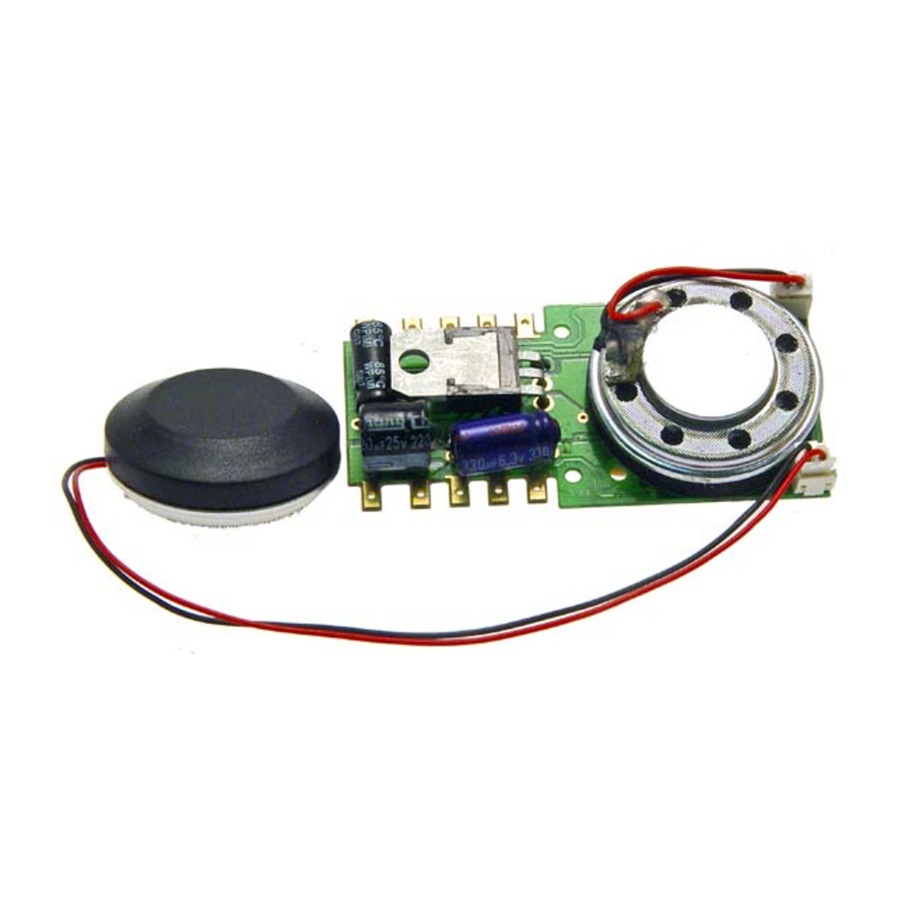
- True stereo sound comes with two 28mm speakers
INSTALLATION

Remove the screws that hold down the original PCB. Remove the original PCB and note the locomotives wire colors and locations from where they originate inside the chassis. Before removing the wires from the PCB study all wires and identify the four wheel pickup wires (each side has two wires connnected together) and two motor wires. Light wiring may be different depending the on road name. You must disconnect the motor terminals from the pickups, connect the pickup wires to the pickup tabs. Connect the correct motor terminals to the motor tabs.
The decoder is set up to use the LED or 1.5V bulbs. Install the wires to the decoder as noted in the following diagram. The tab marked common on the decoder is set to 5V for low voltage bulbs or LED's. If the light is not bright enough you can use any wheel pickup tab as common tab. You may need a 1k resistor if the light is too bright. Acc1 or Acc2 are used for extra lighting. This stereo decoder comes with two speakers for the E8/9 which has two diesel engines. Speaker # 2 should be placed in the front.

Standard DC loco wiring diagram:
The 'X' marks indicate where to disconnect (isolate).
OPERATION
The decoder has a default address #3. Select address #3 on your DCC. Release service brake (F5) and dynamic brake (F6). You will hear the brake release sound when you turn off F5. Move up the throttle and the loco should start to move. If the loco does not move on speed 1 you can add more start voltage by programming CV2 with a larger number. You can program the acceleration momentum CV3 and deceleration momentum CV4 to simulate a real train. The decoder has start up and shut down features. If the loco was previously shut down you have to start up the engine first. Press any function key to start up the engine. To shut down the engine you must bring the loco to idle and then press F8 three times.
This decoder has 22 different horns and 8 bells. You can use F19 or program CV50 to select horn. Also use F18 or program CV52 to select bell.
The decoder default is set to automatic notch mode. You can program CV122 to 3 for manual notch mode for realistic operation. In the manual notch mode the notch level is not controlled by loco speed. It is controlled by F9 ( notch up) and F8 ( notch down).
SERVICE BRAKING: To apply service brake set throttle to zero and press F5. The loco will slow down fast and you will hear the brake squeal. You can pump the brake by turning F5 on and off to stop the loco at desired location. The brake rate is proportional to deceleration rate that you program in CV4. If you forget to turn off F5 and move the throttle up. The loco will move. However, when you release the throttle the service brake will apply again. The service brake can only operate when throttle is at 0. If you don't hear the brake sound program CV115 with a value of 2.
DYNAMIC BRAKING: You can use dynamic braking, F6 to reduce the speed. When you turn on F6 the prime mover will notch down to 1 and you will hear the dynamic brake sound and the loco will down. When you release F6 the loco will speed up to the original speed. If you forget to turn off F6 and move throttle up it will automatically disable the dynamic brake and loco will start to move. To apply the dynamic brake again you have to cycle F6 off and on.
BACK EMF LOAD CONTROL (PID CONTROLLER)
This decoder is equipped with adjustable back EMF load control feature. It is a closed loop speed control. With back EMF load control the locomotive will maintain its speed regardless of pulling up hill or driving down hill. You may program the back EMF load control intensity, CV124, to a lower value to get less back EMF load control. This will enable the locomotive to slow down during uphill travel like a real locomotive.
The PID controller contains three components: proportional gain (CV113); the integral gain (CV114); and derivative gain (fixed). Designing (tuning) a PID controller is a kind of "rocket science". So we optimized these gains at the factory but still give the customer final adjustments. We recommend that you do not change these settings. Too much gain may cause the motor to oscilate (become unstable). Too little gain may cause a slow response. Additional knowledge of PID feedback control is required before attempting to adjust CV113 and CV114. If CV113 and CV114 are programmed incorrectly, the locomotive will not run smoothly. Program CV125 to "1" will automatically restore the default PID controller settings. If you can not get the PID controller work properly or you don't know to tune it, you should program CV6 to enable adaptive PID control to let the decoder to select the best back EMF control for your loco. You can also turn off the Back EMF load control by program CV124 with a value of 0 if the adaptive control fails.
LIGHT EFFECT PROGRAMMING CHART FOR CV#117/118/119
The decoder has 17 different lights effects. CV 117 controls both front and rear headlight effects. Use F0 to turn on or off the Headlights. CV118/CV119 control ACC1/ACC2 light effects. Use F3 to turn on or off ACC1 and ACC2. For ditch light operation you must program Cv118 and CV119 to the same ditch light type. In type A the ditch lights will flash when F2 (horn) or F3 is on. In type B the ditch lights will flash when F2 is on and stay on when F3 is on. If you use a value inconsistent with actual headlights, ( CV117), the headlights will default to normal on/off. For example trying to use a value of 14 in CV117 for firebox flicker, the headlights will default to normal on/off.
| Light effect CV117, CV118, CV119 | |
| Value | Light effect |
| 0 | Normal on/off |
| 1 | Dynamo effect (fading) |
| 2 | Dim, bright, off cycle |
| 3 | Rule 17 |
| 4 | Both headlights on |
| 5 | Ditch Light type A |
| 6 | Ditch Light type B |
| 7 | Gyralite |
| 8 | Mars Light |
| 9 | Prime strato light |
| 10 | Single strobe light |
| 11 | Double strobe light |
| 12 | Rotating beacon |
| 13 | Fred-flashing rear end device |
| 14 | Firebox Flicker A |
| 15 | Firebox Flicker B |
| 16 | Engine Exhaust Flicker |
If you use 1.5V bulbs or LED's, you should connect a 1k ohm resistor in series to one of the leads to reduce the voltage. You may need to adjust CV120 to for LED use. If you use Rule17 or the "dim-bright-off" light effect you may also need to program CV116 to adjust the brightness of the dim light.
| Function | Idle/Moving |
| F1 | Bell on/off |
| F2 | Horn |
| F3 | ACC 1 and ACC 2 on/off (CV 118/119) |
| F4 | Coupling 1 |
| F5 | Brake release (idle) / brake squeal (moving) |
| F6 | Dynamic brake on/off |
| F7 | Air hose firing/uncoupling lever |
| F8 | 3 times will shut down when in idle / Manual notch down |
| F9 | Engine cooling fan / Manual notch up |
| F10 | Rail wheel clack (only moving) |
| F11 | Traction air compressor |
| F12 | Change prime diesel mover type, (CV123, 4 types) |
| F13 | Master volume reduce by 1 |
| F14 | Master volume increase by 1 |
| F15 | Air compressor |
| F16 | Flange squeal |
| F17 | Air release |
| F18 | Change bell type (use F1 to turn off bell after adjustment) |
| F19 | Horn type select (total 22 different horns) |
| F20 | Associated loco sound |
| F21 | Change bell volume (use F1 to turn off bell after adjustment) |
| F22 | Change horn volume |
| F23 | Change diesel rumble volume |
| F24 | Safety valve pop |
| F25 | Air release |
| F26 | Flange noise |
| F27 | Sand drop |
| F28 | Ditch light flash enable/disable with Air release (CV 121) |
| CV123 value | Diesel type |
| 0 | Dual EMD 567B prime mover1 |
| 1 | Single EMD 567B prime mover1 |
| 2 | Dual AlCo 244 prime mover2 |
| 3 | Single AlCo 244 prime mover2 |
| 4 | All sounds off |
MRC will provide custom function re-mapping to meet your special railroading requirements, if needed, for a reasonable fee.
PROGRAMMING CV CHART
| CV | Description | Range | Default |
| CV1 | Short address | 1-127 | 3 |
| CV2 | Start voltage | 0-63 | 10 |
| CV3 | Acceleration, 1=1 sec, max is 63 sec to reach top speed | 0-63 | 0 |
| CV4 | Deceleration, 1=1 sec, max is 63 sec to stop at top speed | 0-63 | 0 |
| CV5 | Top voltage, 63=full speed, 0=half of the top speed | 0-63 | 63 |
| CV6 | Adaptive Back EMF control enable. 0=disable, 1=enable | 0-1 | 0 |
| CV29 | Basic configuration | --- | 2 |
| CV7 | Manufacturer version number | --- | 0 |
| CV8 | Manufacturer ID | --- | 143 |
| CV17 | Long address upper byte 192-231 | 192 | |
| CV18 | Long address low er byte | 0-255 | 3 |
| CV19 | Advanced consist address | 0-127 | 0 |
| CV21 | When CV21=0, functions follow its own address. CV21=1, functions follow the consist address | --- | 0 |
| CV37 | 0=normal, 1=F3 and F4 exchange | 0-1 | 0 |
| CV39 | 0=normal, 1=F5 and F6 exchange | 0-1 | 0 |
| CV42 | 0=normal, 1=F8 and F12 exchange | 0-1 | 0 |
| CV49 | Master sound volume, 16=max volume, 0=sound off | 0-16 | 16 |
| CV50 | Horn type | 0-3 | 0 |
| CV51 | Horn volume | 0-15 | 12 |
| CV52 | Bell type | 0-3 | 0 |
| CV53 | Bell volume | 0-15 | 12 |
| CV54 | Bell ring rate | 0-50 | 3 |
| CV55 | Prime mover volume | 0-15 | 12 |
| CV56 | Brake squeal volume | 0-15 | 12 |
| CV57 | Dynamic brake volume | 0-15 | 12 |
| CV58 | Air release volume | 0-15 | 12 |
| CV59 | Air pump volume | 0-15 | 12 |
| CV60 | Safety pop valve volume | 0-15 | 12 |
| CV61 | Engine cooling fan volume | 0-15 | 12 |
| CV62 | Coupling volume | 0-15 | 12 |
| CV63 | F3 control air release enable | 0-1 | 1 |
| CV64 | Rail w heel clack | 0-15 | 12 |
| CV65 | Kick start voltage | 0-63 | 63 |
| CV67-94 | 28 speed steps table w hile CV29.4=1 | 1-255 | linear |
| CV112 | Back EMF start speed adjudstment | 0-7 | 0 |
| CV113 | Back EMF Load control proportional gain Kp | 0-31 | 20 |
| CV114 | Back EMF Load control integral gain Ki | 0-31 | 10 |
| CV115 | Brake soundl type; 2=brake sound off | 0-2 | 0 |
| CV116 | Brightness of dim light in Rule 17 or dim-bright-off mode | 0-255 | 120 |
| CV117 | Headlight light effect | 0-15 | 0 |
| CV118-119 | Accessory light mode | 0-15 | 0 |
| CV120 | Light brightness | 0-255 | 255 |
| CV121 | Air compressor mode (1=change w ith engine rpm) | 0-1 | 0 |
| CV122 | Diesel Notch mode, 0=auto, 3=manual | 0-3 | 0 |
| CV123 | Diesel Primer Mover Select | 0-4 | 0 |
| CV124 | Back EMF Load control intensity (0=off) | 0-255 | 0 |
| CV125 | Programming to "1" w ill restore some CV's to factor settings | --- | 0 |
SPEED TABLE CV67-CV94 FOR 28 SPEED STEPS
When CV29's bit 4 is set to "1" it will use the speed table formed by CV67-CV94 to control speed (motor voltage). It allows you to setup each speed for all 28 speed steps. First, program CV29 to 18 for short addresses (1-127) or program CV29 to 50 for long addresses (128-9999) to enable speed table control. Then select throttle to 28 speed steps and run your loco at speed step 1. Use program CV on the main to change CV67's value (1-255) to adjust step 1's speed. The kick voltage, CV65 is only applied when the speed step changes from 0 to 1. You should switch between 0 to 1 many times to check step 1's speed. When done with CV67, select speed step 2 and program CV68. CV68's value must be greater then CV67's. When done with CV67-CV94, use read back CV to make sure their values are in increasing order.
Note: When using MRC Prodigy DCC to program addresses it will automatically disable the speed table (set CV29's bit 4 to "0"). Programming CV125 to 1 will also disable the speed table and re-program CV67-CV94 to a default linear speed setting.
TROUBLE SHOOTING
Loco running without any sound press F12, no chuff sound, press F6. Whenever the decoder doesn't work please use the program track to program CV #125 with value 1 to restore the decoder to factory settings. This should bring the decoder to life with address #3. This decoder should perform well with all DCC systems. The maximum DCC output should be less than 18 V. If the locomotive does not respond to commands, it may have lost its address. Please re-program the address and program CV19 to 0 (disable consist). If it responds slowly, you should clear its momentum by reprogramming CV3 and CV4 to zero. If step 1's speed is too high, you should program start voltage, CV2 to zero. If its top speed is too slow, program top voltage CV5 to 31. You should also clean the track to improve electrical pickup. Read your DCC system manual to learn how to program and operate the decoder. For more information about registers/CVs and their functions, please refer to the NMRA DCC Standard & Recommended Practices, RP-9.2.2. This is available directly from the NMRA or their website at www.nmra.org.
Send the decoder to:
Model Rectifier Corporation
Attn: Parts & Service
80 Newfield Avenue
Edison, NJ 08837-3817 U.S.A

Documents / Resources
References
Download manual
Here you can download full pdf version of manual, it may contain additional safety instructions, warranty information, FCC rules, etc.
Advertisement


Need help?
Do you have a question about the 0001922 and is the answer not in the manual?
Questions and answers