Table of Contents
Advertisement
Quick Links
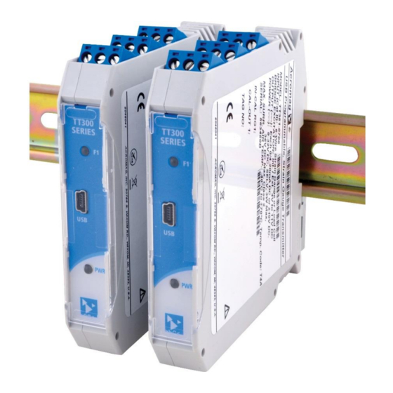
Model TT351-07x0, Bridge Input Transmitter
(Strain Gauges, Load Cell, or ±4mV to ±165mV DC)
USB Programmable, DIN Rail Mount, DC-Powered
Single Channel Transmitter w/
Sourcing Current or Voltage Output
USER'S MANUAL
ACROMAG INCORPORATED
Tel: (248) 295-0880
30765 South Wixom Road
Wixom, MI 48393-2417 U.S.A.
email: sales@acromag.com
Copyright 2018, Acromag, Inc., Printed in the USA.
8501140D
Data and specifications are subject to change without notice.
Advertisement
Table of Contents

Related Manuals for Acromag TT351-07 0 Series


Summary of Contents for Acromag TT351-07 0 Series
- Page 1 Sourcing Current or Voltage Output USER’S MANUAL ACROMAG INCORPORATED Tel: (248) 295-0880 30765 South Wixom Road Wixom, MI 48393-2417 U.S.A. email: sales@acromag.com Copyright 2018, Acromag, Inc., Printed in the USA. 8501140D Data and specifications are subject to change without notice.
-
Page 2: Table Of Contents
5 Input Calibration ......................45 6 Output Calibration ......................48 7 Diagnostics ........................49 8 Shunt Calibration ......................50 9 Load Cell Calibration ....................... 53 BLOCK DIAGRAM ..................... 54 Acromag, Inc. Tel: 248-295-0880 - 2 - - 2 - https://www.acromag.com http://www.acromag.com... - Page 3 This is very important where property loss or human life is involved. It is important that you perform satisfactory overall system design and it is agreed between you and Acromag, that this is your responsibility.
-
Page 4: Getting Started
Key Features • USB configured and calibrated using Windows software, or a wired USB-OTG connection to Android smartphones or tablets using the Acromag Agility app. • Thin 17.5mm wide enclosure for high-density mounting. • Isolated Input/Exc, Output, & Power – increases safety & noise immunity. -
Page 5: Application
Wheatstone bridge. It can optionally supply variable sensor topics, please visit our web site excitation and will measure both sensor output Vo and coincident excitation Vex, at www.acromag.com. Also see which it uses to compute requisite strain or load and linearly drive an isolated sourcing whitepaper 8500-699: output that supports 0-20mA or 4-20mA current, or ±10V, ±5V, 0-10V, 0-5V voltage... -
Page 6: Din Rail Mounting & Removal
DIN rail clip and use it as a lever to force the DIN rail spring clip down while pulling the bottom of the module outward until it disengages from the rail, and lift it from the rail. Acromag, Inc. Tel: 248-295-0880 - 6 - - 6 - https://www.acromag.com... -
Page 7: Electrical Connections
(use the config software to set Excitation to Ext). • clip side). Follow proper polarity Complete input connections prior to power-up to avoid propagating input offset. when making input connections. Acromag, Inc. Tel: 248-295-0880 - 7 - - 7 - https://www.acromag.com http://www.acromag.com... - Page 8 Model TT351-07x0 Strain Gauge Input Transmitter w/USB Sensor Input Connections... Acromag, Inc. Tel: 248-295-0880 - 8 - - 8 - https://www.acromag.com http://www.acromag.com...
-
Page 9: Digital Input Connections (Tare)
Variations in output load resistance has negligible effect on output accuracy sensor Gauge Factor and a when load limits are respected with respect to output type (see below). software gain of 1. Acromag, Inc. Tel: 248-295-0880 - 9 - - 9 - https://www.acromag.com... - Page 10 For sensitive applications with high-speed acquisition at the load, high frequency noise may be reduced significantly by placing a 0.1uF capacitor directly across the load, and as close to the load as possible. Acromag, Inc. Tel: 248-295-0880 - 10 - - 10 - https://www.acromag.com...
-
Page 11: Power Connections
This transmitter can be optionally powered (or redundantly powered) via the supply capable of delivering more DIN rail bus when coupled to an optional DIN rail bus connector (Acromag Model than 3A to the unit, it is 1005-063) with a bus terminal block (Acromag 1005-220 or 1005-221). This optional... -
Page 12: Optional Bus Power Connections
Important – End Stops: If this module uses the optionally powered (or redundantly powered) via the DIN rail bus for hazardous location installations (Class I, Division 2 or ATEX/IECEx Zone 2) it must use two end stops (Acromag 1027-222) to secure the terminal block and module (not shown). -
Page 13: Earth Ground Connections
(A PC commonly earth grounds its USB port contacting both the USB signal and shield ground which are held in common to the input circuit ground of this transmitter). Acromag, Inc. Tel: 248-295-0880 - 13 - - 13 - https://www.acromag.com... -
Page 14: Usb Connections
Windows-based PC connected to the unit via USB (Windows 7 or later required), or via a USB-OTG connection to an Android smartphone or tablet using the Acromag Agility mobile app. Refer to the drawing below to connect your PC or laptop to the transmitter to reconfigure or calibrate it using this software. -
Page 15: Emi Filter Installation
Note that individual cables may share a ferrite, but it is not good practice to combine isolated circuits inside the same ferrite, but rather separate isolated circuits for safety and greater noise immunity. Acromag, Inc. Tel: 248-295-0880 - 15 - - 15 - https://www.acromag.com... -
Page 16: Introduction To Strain
Vo and the sensor bridge excitation Vex. Using sensor milli-strain ( =0.003 or about specifications and these two measurements, the applied strain or load can be 3000 resolved from the bridge output signal. Acromag, Inc. Tel: 248-295-0880 - 16 - - 16 - https://www.acromag.com http://www.acromag.com... - Page 17 Adverse effects like this are the reason strain instruments provide additional parametric controls for rescaling their measurement as required, like utilizing Instrument Gauge Factor and Software Gain to help overcome application-induced skew in strain measurement. Acromag, Inc. Tel: 248-295-0880 - 17 - - 17 - https://www.acromag.com...
-
Page 18: The Wheatstone Bridge
Thus, bridge Vo will grow positive for a compressive stress on R4 driving negative strain and decreasing its resistance. This is the convention used throughout this manual. Acromag, Inc. Tel: 248-295-0880 - 18 - - 18 - https://www.acromag.com... - Page 19 Vo signal. Acromag, Inc. Tel: 248-295-0880 - 19 - - 19 - https://www.acromag.com...
- Page 20 Poisson’s ratio where applicable using permutations of the three basic bridge configurations: quarter, half, and full, where applicable. Acromag, Inc. Tel: 248-295-0880 - 20 - - 20 - https://www.acromag.com...
-
Page 21: Strain Bridge Equations
Poisson’s strain ±v. An active gauge measures axial strain when mounted in the same direction as the applied force and bending strain when mounted in a lateral direction to the applied force. Acromag, Inc. Tel: 248-295-0880 - 21 - - 21 - https://www.acromag.com... - Page 22 For Quarter-Bridge Type I or Type II, solving for the resultant strain will yield the following expression (note the absence of Poisson’s Ratio because it is often ignored at lower levels of strain less than ~5000µ): = (1 + Rl/Rg) * -4Vr/[GF*(1+2Vr)] Acromag, Inc. Tel: 248-295-0880 - 22 - - 22 - https://www.acromag.com...
- Page 23 Recall that diagonally opposite gauges reinforce each other for resistance/strain changes in the same direction, while adjacent gauges tend to cancel each other for resistance/strain in the same direction. Acromag, Inc. Tel: 248-295-0880 - 23 - - 23 - https://www.acromag.com...
- Page 24 Less Sensitive to than Type I strain (i.e. bottom of beam). Solving for the Full-Bridge Type II strain yields: Comp for Poisson’s (Higher ) = -2Vr / [GF*( + 1)]. Acromag, Inc. Tel: 248-295-0880 - 24 - - 24 - https://www.acromag.com...
- Page 25 Gauge Factor is initially set to 2 (roughly equivalent to the sensor Gauge Factor) and this makes indicated strain roughly equivalent to ideal strain, insofar as much as the application induced error is kept to a minimum. Acromag, Inc. Tel: 248-295-0880 - 25 - - 25 - https://www.acromag.com...
-
Page 26: Resolving Strain Or Load
“dummy” resistor be connected, while Type II will require an adjacent “dummy” gauge be connected to closely match the temperature coefficient of the active gauge over temperature. Acromag, Inc. Tel: 248-295-0880 - 26 - - 26 - https://www.acromag.com... - Page 27 Poisson’s contribution is greater. Use this figure to discern gauge positions and how they will affect the output signal magnitude and polarity. Acromag, Inc. Tel: 248-295-0880 - 27 - - 27 - https://www.acromag.com...
- Page 28 If HB completion is included, you can connect the bridge completion resistors to IN+ instead of IN- to flip the polarity of the bridge output Vo and remove the negative sign preceding each equation. Acromag, Inc. Tel: 248-295-0880 - 28 - - 28 - https://www.acromag.com...
-
Page 29: How The Tt351 Measures Strain And Load
ENOB2 per Gain2=1 and Input Filter from Specifications Table 1 and Resolution = ±10^[|ENOB-1|*LOG2] ADC Count 2 = |Resolution|*Vref1/Vref2 + |Resolution-1| Strain Computation Term Vr=Vo/Vex (see Strain formula per Bridge Type) Acromag, Inc. Tel: 248-295-0880 - 29 - - 29 - https://www.acromag.com... -
Page 30: Example Calculation For A Strain Gauge
Instrument Gauge Factor is substituted for Gauge Factor and a software gain different than 1 may be applied to scale the unit’s computed load or strain as required by your application, set during shunt-calibration or load cell calibration. Acromag, Inc. Tel: 248-295-0880 - 30 - - 30 - https://www.acromag.com... -
Page 31: Example Calculation For A Load Cell
32767 = 35453. Using this count, the unit solves for the Vo voltage, leading to Vo = measurements (see Minimum Load (34110-32767) *1.3661/(32*32768) = 0.0035V for our example. specification). Acromag, Inc. Tel: 248-295-0880 - 31 - - 31 - https://www.acromag.com... - Page 32 Specification Table 3). Acromag, Inc. Tel: 248-295-0880 - 32 - - 32 - https://www.acromag.com...
-
Page 33: Configuration Software
Strain Gauge Input Transmitter w/USB CONFIGURATION SOFTWARE Quick Overview – Android This transmitter can be setup & calibrated via the Acromag Agility™ Config Tool. This software APP can be downloaded free of charge from play.google.com. To connect to this transmitter, a USB OTG (On-The-Go) cable (5028-565) and USB A to Mini-B cable (4001-113) are required. -
Page 34: Quick Overview - Windows
[?] button in the upper-right hand corner page. of the screen and then click to point to a field or control to get a Help message pertaining to the item you pointed to. Acromag, Inc. Tel: 248-295-0880 - 34 - - 34 - https://www.acromag.com... - Page 35 Please use the Module pull-down menu selection Send Configuration to write your configuration page changes to the connected module before changing to the next page. Acromag, Inc. Tel: 248-295-0880 - 35 - - 35 - https://www.acromag.com http://www.acromag.com...
- Page 36 Help message pertaining to the item you pointed to. Acromag, Inc. Tel: 248-295-0880 - 36 - - 36 - https://www.acromag.com...
-
Page 37: Technical Reference
Now that you have made your connections and applied power, you can execute the TT351Config.exe software to begin configuration and testing (software is compatible with v7 or later versions of the Windows operating system). Acromag, Inc. Tel: 248-295-0880 - 37 - - 37 - https://www.acromag.com... - Page 38 1.800 SHUNT CALIBRATION Calibration Element Shunt Resistance Ohms Software Gain 1.000 Instrument Gauge Factor 2.000 LOAD CALIBRATION Reference Load 100.000 %FSR Software Gain 1.000 Indicated Load 100.000 %FSR Acromag, Inc. Tel: 248-295-0880 - 38 - - 38 - https://www.acromag.com http://www.acromag.com...
-
Page 39: Communication Setup
(TT300 models do not draw power from USB). After executing the Acromag Configuration software for the TT351, the screen shown at left will appear, if you have not... -
Page 40: 2 I/O Configuration
The only other way to preserve changes you make is to optionally save them to a reference file by using the “File – Save As...” pull-down menu command. Acromag, Inc. Tel: 248-295-0880 - 40 - - 40 - https://www.acromag.com... -
Page 41: Sensor Setup
Please use the Module pull-down menu selection Send Configuration to write your configuration page changes to the connected module before changing to the next page. Acromag, Inc. Tel: 248-295-0880 - 41 - - 41 - https://www.acromag.com... - Page 42 The remaining information varies according to the Input Type selection, SG Bridge type or Load Cell. Parameter fields that do not apply to your type selection will be grayed out on-screen. Acromag, Inc. Tel: 248-295-0880 - 42 - - 42 - https://www.acromag.com...
- Page 43 ADC input signal gain is set to adjust Vex as needed to boost its level if it droops too far 1,2,4,8,16,32,64, or 128 < REF1/|RO*Vex*OVR%/100|. below the nominal you select here. Acromag, Inc. Tel: 248-295-0880 - 43 - - 43 - https://www.acromag.com...
-
Page 44: Scaling/Computation
25 indicated input-to-output break points to to the connected module before changing to the next facilitate your own 24-segment linearization of the sensor’s page. indicated load/strain. Acromag, Inc. Tel: 248-295-0880 - 44 - - 44 - https://www.acromag.com http://www.acromag.com... -
Page 45: Input Calibration
DVM measurements, so be careful to accurately measure and record the MIN/MAX excitation levels to 4 decimal places. Acromag, Inc. Tel: 248-295-0880 - 45 - - 45 - https://www.acromag.com... - Page 46 (see the Diagnostics page for software Tare controls). values change more frequently for a sensor, while initial offset usually remains constant for the application sensor. Acromag, Inc. Tel: 248-295-0880 - 46 - - 46 - https://www.acromag.com http://www.acromag.com...
- Page 47 For computation of ideal or simulated strain values, the gain is 1 and the Gauge Factor of the sensor is used. In the calibration pages that follow, if you ever need to restore a calibration (or just the configuration), you can click on Module Restore… Acromag, Inc. Tel: 248-295-0880 - 47 - - 47 - https://www.acromag.com...
-
Page 48: Output Calibration
[Restore to Factory Default] Use to return the unit to its original factory configuration settings (does not restore calibration, only configuration). Useful as a sanitation tool to restore initial configuration when decommissioning a module. Acromag, Inc. Tel: 248-295-0880 - 48 - - 48 - https://www.acromag.com... -
Page 49: Diagnostics
(the measured excitation may differ slightly from your specified value due to limitations of adjustment resolution). The “Status” line will typically display “No error” in the Communication status field while polling. Acromag, Inc. Tel: 248-295-0880 - 49 - - 49 - https://www.acromag.com... -
Page 50: Shunt Calibration
Indicated Value is used to drive the Indicated millivoltage. transmitter output current and voltage range. Acromag, Inc. Tel: 248-295-0880 - 50 - - 50 - https://www.acromag.com... - Page 51 Es as follows: 2 * (1 + ) Full-Bridge Type II & III Es (micro-strain) = - Rg * 10 / (GF* N* (Rs+Rg). Full-Bridge Type I Acromag, Inc. Tel: 248-295-0880 - 51 - - 51 - https://www.acromag.com http://www.acromag.com...
- Page 52 (the Indicated Value is used to drive the transmitter’s analog output). You typically adjust Instrument Gauge Factor and/or Software Gain and click [Measure], until your indicated measurement closely matches the ideal or72 Simulated Strain. Acromag, Inc. Tel: 248-295-0880 - 52 - - 52 - https://www.acromag.com...
-
Page 53: Load Cell Calibration
[Calc Gain]: Click this button to have the software calculate the required Software Gain to equate Indicated Load with Reference Load. [Measure]: Click this button to utilize Software Gain and take a new measurement of Indicated Load. Acromag, Inc. Tel: 248-295-0880 - 53 - - 53 - https://www.acromag.com http://www.acromag.com... -
Page 54: Block Diagram
ADC, allowing it to boost the regulator output as from input ground. needed to closely match the required excitation and this helps overcome droop at the bridge. Acromag, Inc. Tel: 248-295-0880 - 54 - - 54 - https://www.acromag.com... - Page 55 ~4(10/73.2) to ~11(10/73.2), or REF1=0.5464V-1.5027V and is measured relative to REF2=1.8V (no gain is applied to REF1 measurement). Its measurement resolution is computed via its ENOB at gain=1 and filter level with count= ±resolution*REF1/1.8 + |resolution-1|). Acromag, Inc. Tel: 248-295-0880 - 55 - - 55 - https://www.acromag.com...
-
Page 56: Troubleshooting
Acromag. USB connection to your tablet/ phone to get this prompt. USB has not enumerated Use the Acromag USB isolator reset button to the device. trigger renumeration of the unit, or simply unplug/re-plug the USB cable to the transmitter. Software Fails to Detect Transmitter…... - Page 57 Acromag for repair or replacement. Acromag has Changing Input Filter Setting Affects Input Calibration… automated test equipment that You may notice a small shift This is normal.
-
Page 58: Service & Repair Assistance
Please refer to Acromag’s Service Policy and Warranty Bulletins or contact Acromag for complete details on how to obtain repair or replacement. Acromag, Inc. Tel: 248-295-0880 - 58 - - 58 - https://www.acromag.com... -
Page 59: Accessories
This is a 1-meter, USB A-miniB replacement cable for connection between the USB isolator and the DT/SP/TT33x transmitter. It is normally included in TTC-SIP. Note that Windows-USB or Android-USB OTG software for all DT/TT/SP Series models is available free of charge, online at www.acromag.com. Acromag, Inc. Tel: 248-295-0880 - 59 - - 59 - https://www.acromag.com... -
Page 60: Usb Otg Cable
This is a 6 inch, USB On-The-Go cable for connection between the USB A-mini B Cable and a mobile phone or tablet. It is required to use the Acromag Agility™ Config Tool App on an Android smartphone or tablet to configure the unit. -
Page 61: Specifications
1mV/V to 10mV/V (RO is sometimes referred to as sensor electrical sensitivity). The ADC sets its input range for the sensor Vo signal as the ±product of excitation Vex, Rated Output, and user-specification for Over-Load%/100. Acromag, Inc. Tel: 248-295-0880 - 61 - - 61 - https://www.acromag.com... - Page 62 HALF bridge completion jumper from input H to BRG- to bias the differential input signal or measurement error may result (see Electrical Connections). You may modify software gain on the Shunt Calibration page to scale your mV input. Acromag, Inc. Tel: 248-295-0880 - 62 - - 62 - https://www.acromag.com...
- Page 63 Note: At medium and high filter settings, the heavily attenuated 60Hz signal cannot be measured due to 4 order filtering by the input ADC which adds 80dB minimum of rejection at frequencies between 47Hz and 61Hz. Acromag, Inc. Tel: 248-295-0880 - 63 - - 63 - https://www.acromag.com...
- Page 64 ADC or output DAC (see output resolution). To calculate the equivalent number of bits of resolution corresponding to 0-100% of range having 43420 parts, NOB=LOG(Resolution)/LOG(2) = LOG(43420)/LOG(2)=15.4 bits. Acromag, Inc. Tel: 248-295-0880 - 64 - - 64 - https://www.acromag.com...
- Page 65 The TT351 has a unique feature built into its Over-Range OVR specification that can be used to increase input resolution for some applications by limiting the application over-range below 150%, and this is explained below: Acromag, Inc. Tel: 248-295-0880 - 65 - - 65 - https://www.acromag.com...
-
Page 66: Output
1 bit for every halving of this range. The actual I/O resolution is the lowest resolution of the input A/D and output D/A relative to the I/O range. Acromag, Inc. Tel: 248-295-0880 - 66 - - 66 - https://www.acromag.com... -
Page 67: Power
9V minimum must be maintained 127mA Max across the unit during operation. 95mA Max Power Supply Effect: Less than 0.001% of output span effect per volt DC change. Acromag, Inc. Tel: 248-295-0880 - 67 - - 67 - https://www.acromag.com http://www.acromag.com... -
Page 68: Usb Interface
(resistance is greater than 525Ω). ON may also indicate over-temperature if the output die temperature has exceeded 142°C. Acromag, Inc. Tel: 248-295-0880 - 68 - - 68 - https://www.acromag.com... -
Page 69: Environmental
UL 20 ATEX 2416X IECEx UL 20.0088X X = Special Conditions The equipment shall only be used in an area of not more than pollution degree 2, as defined in EN/IEC 60664‐1. Acromag, Inc. Tel: 248-295-0880 - 69 - - 69 - https://www.acromag.com... -
Page 70: Reliability Prediction
• Provides controls to reset the module. • Provides controls to adjust the output independent of the input signal. Acromag, Inc. Tel: 248-295-0880 - 70 - - 70 - https://www.acromag.com http://www.acromag.com... -
Page 71: Revision History
Added MTBF, Bandwidth, changed Filter Default to Medium. 15-SEP-2020 CAP/ARP Added cULus, ATEX, IECEx, and FCC approvals. 28 JAN 2022 CAP/AMM Added Altitude: Up to 2000 meters (Environmental Section) Acromag, Inc. Tel: 248-295-0880 - 71 - - 71 - https://www.acromag.com http://www.acromag.com...
Need help?
Do you have a question about the TT351-07 0 Series and is the answer not in the manual?
Questions and answers