Table of Contents
Advertisement
Quick Links
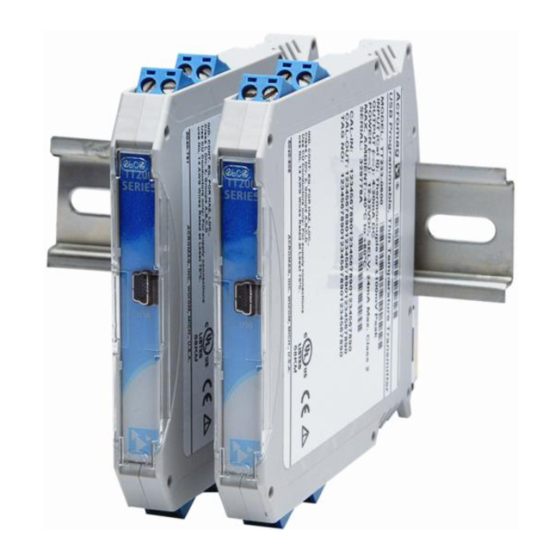
USB Programmable, DIN Rail Mount
Thin Temperature Transmitter
Model TT231-0600
RTD Input, Two-Wire Transmitter
USER'S MANUAL
ACROMAG INCORPORATED
Tel: (248) 295-0880
30765 South Wixom Road
Fax: (248) 624-9234
Wixom, MI 48393-7037 U.S.A.
email: sales@acromag.com
Copyright 2012, Acromag, Inc., Printed in the USA.
8500-935C
Data and specifications are subject to change without notice.
Advertisement
Table of Contents

Related Manuals for Acromag TT231-0600


Summary of Contents for Acromag TT231-0600
- Page 1 RTD Input, Two-Wire Transmitter USER’S MANUAL ACROMAG INCORPORATED Tel: (248) 295-0880 30765 South Wixom Road Fax: (248) 624-9234 Wixom, MI 48393-7037 U.S.A. email: sales@acromag.com Copyright 2012, Acromag, Inc., Printed in the USA. 8500-935C Data and specifications are subject to change without notice.
-
Page 2: Table Of Contents
Pt RTD Resistance Versus Temperature Table ................22 Over-Scale & Under-Scale Thresholds ................. 23 Break Detection ......................... 24 Read Status ........................24 Reset Unit .......................... 25 Restore Factory Settings ....................25 Acromag, Inc. Tel: 248-295-0880 - 2 - http://www.acromag.com - 2 - http://www.acromag.com... - Page 3 This is very important where property loss or human life is involved. It is important that you perform satisfactory overall system design and it is agreed between you and Acromag, that this is your responsibility.
-
Page 4: Getting Started
DESCRIPTION Symbols on equipment: The TT231-0600 is an ANSI/ISA Type II transmitter designed to interface with a Platinum RTD sensor (Resistance Temperature Detector), or resistance input, and modulate a 4-20mA current signal for a two-wire current loop. This unit is setup and calibrated using configuration software and a USB connection to Windows- based PC’s (Windows XP and later versions only). -
Page 5: Mechanical Dimensions
DIN rail clip and use it as a lever to force the DIN rail spring clip down while pulling the bottom of the module outward until it disengages from the rail. Then simply lift it from the rail. Acromag, Inc. Tel: 248-295-0880 - 5 - http://www.acromag.com - 5 - http://www.acromag.com... -
Page 6: Electrical Connections
As a rule, output wires are normally separated from input wiring for safety, as well as for low noise pickup. Acromag, Inc. Tel: 248-295-0880 - 6 - http://www.acromag.com - 6 - http://www.acromag.com... -
Page 7: Sensor Input Connections
4, as shown in the 3-wire connection figure below. Four-Wire Input Sensors Use 3-Wire Lead Compensation. BOTTOM VIEW INPUT SIDE OUTPUT SIDE MODEL TT231-0600 INPUT SENSOR WIRING FRONT (INPUT SIDE) PLATINUM RTD OR RESISTANCE INPUT SHIELDED CABLE... -
Page 8: Output/Power Connections
USB isolation (see USB Connections section). Always connect the output/power wires and apply loop power before connecting the unit to USB. MODEL TT231-0600 OUTPUT/POWER WIRING TRADITIONAL LOOP-POWERED "SINKING OUTPUT" CONNECTIONS TOP VIEW INPUT SIDE... - Page 9 “sinking” inputs, and these will require that a separate power supply connect within the loop. These types of receivers are depicted below: MODEL TT231-0600 OUTPUT WIRING COMMON TWO-WIRE TRANSMITTER CONNECTION TO "SOURCING" AND "SINKING" INPUT RECEIVERS "SINKING OUTPUT" CONNECTIONS WITH...
-
Page 10: Earth Ground Connections
“sourcing” entity from this “sinking” output as shown. LOCAL 24VDC MODEL TT231-0600 OPTIONAL OUTPUT WIRING POWER SUPPLY OPTIONAL "SOURCING OUTPUT" CONNECTIONS WITH POWER LOCAL TO TRANSMITTER... -
Page 11: Usb Connections
1 ea, Model TT-CONFIG CDROM Software USB Signal Isolation is Required (See Below) - You may use Acromag model USB-ISOLATOR to isolate your USB port, or you can optionally use another USB signal isolator that supports USB Full Speed operation (12Mbps). -
Page 12: Configuration Software
Configuration Software and a USB connection to your PC or laptop. The configuration software can be downloaded free of charge from our web site www.acromag.com. This software is also included on a CDROM bundled with the Configuration Kit TTC-SIP (see Accessories section). - Page 13 The system message bar at the bottom of the screen will display & repeat prompt instructions as you step through calibration. It also displays diagnostic messages after clicking “Read Status”. Acromag, Inc. Tel: 248-295-0880 - 13 - http://www.acromag.com - 13 -...
-
Page 14: Technical Reference
Now that you have made your connections and applied power, you can execute the TT231Config.exe software to begin configuration of your unit (software is compatible with XP or later versions of the Windows operating system). Acromag, Inc. Tel: 248-295-0880 - 14 - http://www.acromag.com - 14 -... -
Page 15: Configuration
Model TT231-0600 Two-Wire RTD Transmitter w/USB Configuration After executing the Acromag Configuration software for this model, a screen similar Note that without a device already to the following will appear if you have not already connected to your transmitter connected via USB, the Device... - Page 16 If you select “Resistance”, your output current will be linear with respect to sensor resistance, not temperature, and no special linearization will be performed. Acromag, Inc. Tel: 248-295-0880 - 16 - http://www.acromag.com - 16 - http://www.acromag.com...
- Page 17 For your input range, select the temperature units in degrees Celsius or degrees Fahrenheit. Note that input ranges specified in degrees Fahrenheit will have a fixed input range zero of 0°F. Units in °C can chose an input range zero of -50°C or 0°C. Acromag, Inc. Tel: 248-295-0880 - 17 - http://www.acromag.com - 17 - http://www.acromag.com...
- Page 18 If the output zero and full-scale points are chosen too close together, performance will be degraded. Use input spans greater than 50°C. Acromag, Inc. Tel: 248-295-0880 - 18 - http://www.acromag.com - 18 -...
-
Page 19: Calibrate I/O Range Selection
For example, this might occur for very tight input spans, or odd endpoints. The Configuration Software will usually let you know when you need to adjust your desired limits as you enter them. Acromag, Inc. Tel: 248-295-0880 - 19 - http://www.acromag.com - 19 - http://www.acromag.com... -
Page 20: Zero, Full-Scale, & Linearizer Calibration Procedure
(your output is already linear with resistance). You simply need to click the Complete Calibration button to continue and your resistance transmitter should be calibrated. Acromag, Inc. Tel: 248-295-0880 - 20 - http://www.acromag.com - 20 -... - Page 21 Also, make sure that you have an adequate input span, as too-tight input spans will magnify error. Acromag, Inc. Tel: 248-295-0880 - 21 - http://www.acromag.com - 21 -...
-
Page 22: Pt Rtd Resistance Versus Temperature Table
+ 700 345.28 349.18 + 750 360.64 364.79 + 800 375.70 380.10 + 850 390.48 395.12 Note: Shaded values fall outside the supported zero range for the TT231. Acromag, Inc. Tel: 248-295-0880 - 22 - http://www.acromag.com - 22 - http://www.acromag.com... -
Page 23: Over-Scale & Under-Scale Thresholds
RTD lead to check your O/U alarm limits, which should be ~0.4mA below the under-scale threshold for a downscale break, or 1mA above your over-scale threshold for an upscale break. Acromag, Inc. Tel: 248-295-0880 - 23 - http://www.acromag.com - 23 - http://www.acromag.com... -
Page 24: Break Detection
Input exceeds Positive Limit)”. A break in the third lead that connects to terminal 4 will return “Fault Code: 5 (Positive Input exceeds positive Limit and Negative Input exceeds Positive Limit)”. Acromag, Inc. Tel: 248-295-0880 - 24 - http://www.acromag.com - 24 -... -
Page 25: Reset Unit
Note that the “Reset Unit” control of Unit Status sends the unit to its power-up or stored configuration, different from this control which sends the unit to its initial factory configuration. Acromag, Inc. Tel: 248-295-0880 - 25 - http://www.acromag.com - 25 - http://www.acromag.com... - Page 26 “Calibration Complete!” “Measured Current Output Box accepts positive numbers with up to 4 decimal numbers.” “Error connecting to module! Only model TT231-0600 is compatible with this software!” “Reset Complete! Output Span accepts positive numbers with up to 4 decimal numbers.”...
-
Page 27: Block Diagram
Model TT231-0600 Two-Wire RTD Transmitter w/USB BLOCK DIAGRAM TT231-0600 SIMPLIFIED SCHEMATIC (FILTERING AND DETAIL OMITTED FOR CLARITY) MICRO BUFFER USB-TO-SPI EEPROM PORT DRIVER CONVERTER TWO-WIRE OUTPUT 4-20mA SCHOTTKY BRIDGE LOOP+ Transmitter ASIC 9-32VDC 4-20 EARTH GROUND SPI & CTRL CIRCUITS... - Page 28 (in place of the jumper), and for this unit, that third lead can be a different size and type of material than the ±input leads to the sensor. Acromag, Inc. Tel: 248-295-0880 - 28 - http://www.acromag.com - 28 - http://www.acromag.com...
- Page 29 USB signals be isolated when connected to a PC to prevent a ground loop from occurring between the PC earth ground and the traditional current loop earth ground. Acromag, Inc. Tel: 248-295-0880 - 29 - http://www.acromag.com - 29 -...
-
Page 30: Troubleshooting
Verify that power is applied to the cable to the transmitter. loop and that your loop power USB has not enumerated the Use the reset button on the Acromag USB supply voltage is sufficient to device. isolator to trigger renumeration of the... - Page 31 Under- should consult with the factory and arrange Range Value to its lowest for the unit to be returned for repair or setting. replacement. Acromag, Inc. Tel: 248-295-0880 - 31 - http://www.acromag.com - 31 - http://www.acromag.com...
- Page 32 4mA in output current during memory write. The contents of memory is reconfiguration. uploaded at power-up and repeated access of memory is only done during reconfiguration. Acromag, Inc. Tel: 248-295-0880 - 32 - http://www.acromag.com - 32 - http://www.acromag.com...
-
Page 33: Service & Repair Assistance
Acromag has automated test equipment that thoroughly checks and calibrates the performance of each transmitter, and can restore firmware. Please refer to Acromag’s Service Policy and Warranty Bulletins, or contact Acromag for complete details on how to obtain repair or replacement. Acromag, Inc. Tel: 248-295-0880 - 33 - http://www.acromag.com... -
Page 34: Accessories
USB isolator and the TT230 transmitter. It is normally included in TTC- SIP. Note that software for all TT Series models is available free of charge, online at www.acromag.com. Acromag, Inc. Tel: 248-295-0880 - 34 - http://www.acromag.com - 34 -... -
Page 35: Specifications
Scale (up to 850°C/1562°F or 900Ω), and Sensor Fault Detent (Upscale or Downscale). You can obtain form 8500-858 for specifying this calibration from our Custom calibration to your web site at www.acromag.com. specifications can be added as a separate line item at time of The standard model without adding custom factory calibration is calibrated by default for Pt100 RTD, α=0.00385 //C, 3-wire, 0°C to 200°C input, 4 to 20mA... - Page 36 Lead Break/Sensor Burnout Detection: Select output upscale or downscale detection. Alarm output level is indirectly programmed via the linear U/O threshold settings (see Output Fault Limits). Input Bias Current: 50pA typical (PGA), ~doubling every +10°C. Acromag, Inc. Tel: 248-295-0880 - 36 - http://www.acromag.com - 36 -...
-
Page 37: Output
Output Zero Adjust: 4mA nominal, adjustable from 3.5mA to 6mA. Sets value corresponding to 0% of output, and is adjusted independent of under-range threshold. Effective adjustment range is additionally limited via the configuration software. Acromag, Inc. Tel: 248-295-0880 - 37 - http://www.acromag.com - 37 -... -
Page 38: Usb Interface
SHLD Signal Ground (Connects directly to Signal Ground) Note: Most Host Personal Computers (except battery powered laptops) will connect earth ground to the USB shield and signal ground. Acromag, Inc. Tel: 248-295-0880 - 38 - http://www.acromag.com - 38 - http://www.acromag.com... -
Page 39: Enclosure & Physical
2 hours/axis per IEC60068-2-6. Random Vibration: 5G-rms, 5-500 Hz, in 3 axis at 2 hours/axis per IEC60068-2-64. Mechanical Shock: 30g at 11ms half-sine shock pulses and 50g at 3ms half-sine shock pulses in each direction along 3 axis (18 shocks), per IEC60068-2-27. Acromag, Inc. Tel: 248-295-0880 - 39 - http://www.acromag.com - 39 -... -
Page 40: Agency Approvals
Register. All control registers are read/write capable except for the Fault Status Register. Refer to Operation Step-By-Step in the Technical Reference section of this manual for detailed information on available software control of this model. Acromag, Inc. Tel: 248-295-0880 - 40 - http://www.acromag.com - 40 -... -
Page 41: Revision History
ECN #13G017 for additional information. Added note to USB connections drawing, refer to ECN #13F005 for additional information. 16-DEC-13 JEB/ARP Updated MTBF Numbers. Removed P.O. Box from address. Acromag, Inc. Tel: 248-295-0880 - 41 - http://www.acromag.com - 41 - http://www.acromag.com...
Need help?
Do you have a question about the TT231-0600 and is the answer not in the manual?
Questions and answers