Table of Contents
Advertisement
Quick Links
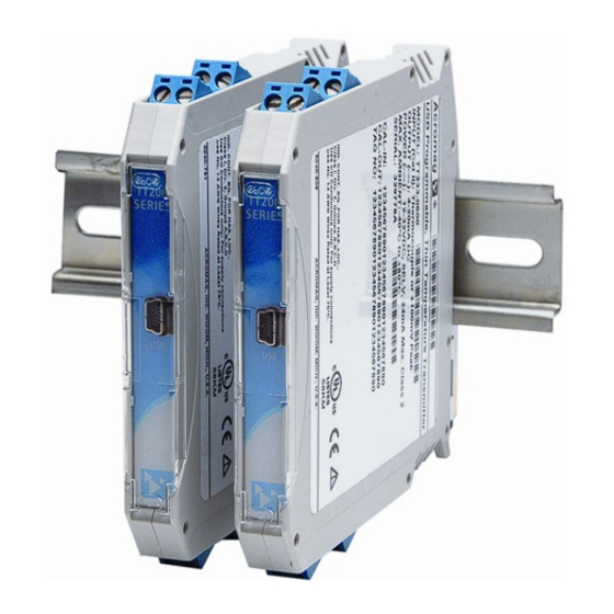
USB Programmable, DIN Rail Mount
Thin Transmitter
Model TT234-0600, Two-Wire Transmitter
NTC Thermistor/Potentiometer/Rheostat Input
4-20mA Output
USER'S MANUAL
ACROMAG INCORPORATED
Tel: (248) 295-0880
30765 South Wixom Road
Fax: (248) 624-9234
Wixom, MI 48393-2417 U.S.A.
email: sales@acromag.com
Copyright 2018, Acromag, Inc., Printed in the USA.
8500994L
Data and specifications are subject to change without notice.
Advertisement
Table of Contents

Related Manuals for Acromag TT234-0600


Summary of Contents for Acromag TT234-0600
- Page 1 4-20mA Output USER’S MANUAL ACROMAG INCORPORATED Tel: (248) 295-0880 30765 South Wixom Road Fax: (248) 624-9234 Wixom, MI 48393-2417 U.S.A. email: sales@acromag.com Copyright 2018, Acromag, Inc., Printed in the USA. 8500994L Data and specifications are subject to change without notice.
-
Page 2: Table Of Contents
Thermistor Resistance versus Temperature ................ 24 BLOCK DIAGRAM ..................25 How It Works ........................25 TROUBLESHOOTING ................26 Diagnostics Table ....................... 26 Service & Repair Assistance ....................27 ACCESSORIES ..................28 Acromag, Inc. Tel: 248-295-0880 - 2 - https://www.acromag.com http://www.acromag.com... - Page 3 Buyer and Acromag, that this is the Buyer's responsibility. The information of this manual may change without notice. Acromag, Inc. makes no warranty of any kind with regard to this material, including, but not limited to, the implied warranties of merchantability and fitness for a particular purpose.
-
Page 4: Getting Started
GETTING STARTED DESCRIPTION Symbols on equipment: The TT234-0600 is an ANSI/ISA Type 2 transmitter designed to interface with thermistors and potentiometers/rheostats, isolate the input signal, and modulate a 4-20mA current signal to drive a two-wire current loop. Thermistor sensor excitation, linearization, and lead break or sensor burnout detection are supported. -
Page 5: Mechanical Dimensions
DIN rail clip and use it as a lever to force the DIN rail spring clip down while pulling the bottom of the module outward until it disengages from the rail. Tilt the module upward to lift it from the rail. Acromag, Inc. Tel: 248-295-0880 - 5 - https://www.acromag.com... -
Page 6: Electrical Connections
Use a screwdriver to tighten the screw by turning it in a clockwise direction to secure the wire (0.5-0.6Nm torque). Since common mode voltages can exist on signal wiring, adequate wire insulation should Acromag, Inc. Tel: 248-295-0880 - 6 - https://www.acromag.com... -
Page 7: Sensor Input Connections
Important – End Stops: For hazardous location installations (Class I, Division 2 or ATEX/IECEx Zone 2) it must us two end stops (Acromag 1027-222) to secure the module(s) to the DIN rail (not shown). -
Page 8: Output/Power Connections
This makes it flexible in the way it connects to various “Receiver” devices. Acromag, Inc. Tel: 248-295-0880 - 8 - https://www.acromag.com... - Page 9 TIP – Inductive Loads: If the two-wire current loop includes a highly inductive load (such as an I/P current-to-pressure transducer), this may reduce output stability. In this case, place a 0.1uF capacitor directly across the inductive load and this will typically cure the problem. Acromag, Inc. Tel: 248-295-0880 - 9 - https://www.acromag.com http://www.acromag.com...
-
Page 10: Earth Ground Connections
(PC USB ports are commonly earth grounded and make contact with both the USB signal and shield ground which is held in common to the input circuit ground of the transmitter). Acromag, Inc. Tel: 248-295-0880 - 10 - https://www.acromag.com http://www.acromag.com... -
Page 11: Usb Connections
1 ea, Model USB-ISOLATOR 1 ea, Configuration Software CDROM 5040-944 • USB Signal Isolation is Required (See Below) – Acromag model USB-ISOLATOR may be used to isolate the USB port, or optionally, another USB signal isolator that supports USB Full Speed operation (12Mbps). -
Page 12: Configuration Software
CONFIGURATION SOFTWARE Quick Overview – Android This transmitter can be configured and calibrated via the Acromag Agility™ Config Tool App. This software can be downloaded free of charge from the Google Play store at play.google.com. To connect to this transmitter, a USB OTG (On-The-Go) cable (Acromag 5028-565) and USB A to Mini-B cable (Acromag 4001-113) are required. -
Page 13: Quick Overview - Windows
USB connection to a PC or laptop. The configuration software is contained in a zip file that can be downloaded free of charge from our web site at www.acromag.com. If you do not yet have a user account, you will need to create one before the download becomes accessible. - Page 14 Click the [Input Cal Instructions] button to begin input calibration. When you click [Zero-Scale] or [Full-Scale] of the Input Calibration section, you will be prompted to connect input pins together or apply a specific Acromag, Inc. Tel: 248-295-0880 - 14 - https://www.acromag.com...
-
Page 15: Operation Step-By-Step
You will need to measure the output current accurately in order to calibrate the transmitter. You can connect a current meter in series in this loop to read the loop current directly (not Acromag, Inc. Tel: 248-295-0880 - 15 - https://www.acromag.com... - Page 16 Now that you have made your connections and applied power to your loop, you can execute the “TT234 Config.exe” software to begin configuration of the transmitter (software is compatible with XP or later versions of the Windows operating system). Acromag, Inc. Tel: 248-295-0880 - 16 - https://www.acromag.com http://www.acromag.com...
- Page 17 You will not be able to calibrate, or test the transmitter without power applied. After executing the Acromag Configuration software for this transmitter, the window shown at left will appear, if you have not already connected to the transmitter via USB (note fields are blank under these conditions).
-
Page 18: Configuration
Under-range and over-range limits are 5% outside the nominal output range selected. NOTE: Potentiometer input types do not support break direction. Acromag, Inc. Tel: 248-295-0880 - 18 - https://www.acromag.com http://www.acromag.com... - Page 19 If the transmitter will be interfacing with a thermistor, the Specifications for more detail. Thermistor Config Table needs to be updated and/or verified. Proceed to the next section for instructions on this process. Acromag, Inc. Tel: 248-295-0880 - 19 - https://www.acromag.com http://www.acromag.com...
- Page 20 After all 3 Steinhart-Hart coefficients have been entered, click “Submit Coefficients”. The Configuration Software will then generate a custom Thermistor Resistance- Temperature table using the Steinhart-Hart equation and the coefficients submitted. Acromag, Inc. Tel: 248-295-0880 - 20 - https://www.acromag.com http://www.acromag.com...
- Page 21 Thermistor Table for erroneous or included in the internal extraneous values. Break-points that are flagged will be representation. highlighted using the color scheme detailed in the Validation Color Key on the left. Acromag, Inc. Tel: 248-295-0880 - 21 - https://www.acromag.com http://www.acromag.com...
-
Page 22: Calibration (Optional)
Since input levels cannot be validated during calibration, incorrect signal levels will produce an undesired output response. Acromag, Inc. Tel: 248-295-0880 - 22 - https://www.acromag.com http://www.acromag.com... - Page 23 This field displays calibration status messages such as “No Error”, “No Device Connected”, “Calibration Error”, “Transfer Error”, and “Timeout Error” during calibration. If you encounter an error, you may have to repeat the calibration process. Acromag, Inc. Tel: 248-295-0880 - 23 - https://www.acromag.com http://www.acromag.com...
-
Page 24: Thermistor Resistance Versus Temperature
��1 �� �� = 3978.73 �� /�� 25/85 �� −�� �� 358.15−298.15 240.8 ��2 NOTE: T and T must be converted to degrees Kelvin (°K) before using in the formula above. Acromag, Inc. Tel: 248-295-0880 - 24 - https://www.acromag.com http://www.acromag.com... -
Page 25: Block Diagram
Model TT234-0600 Thermistor/Potentiometer/Rheostat Transmitter w/USB BLOCK DIAGRAM ISOLATED OUTPUT TT234-0600 SIMPLIFIED SCHEMATIC (FILTERING AND DETAIL OMITTED FOR CLARITY) POTENTIOMETER OR THERMISTOR/RHEOSTAT INPUT PORT 12-36V 3.3V V-MON 1.25V +/- 30ppm 3.3V 3.XV 3.XV 0.1% TWO-WIRE OUTPUT 3.XV LOOP+ – 12-36VDC 4-20... -
Page 26: Troubleshooting
Bad USB Connection Recheck USB Cable Connection the questionable transmitter with a known good transmitter. Use the reset button on the Acromag USB USB has not enumerated the isolator to trigger re-enumeration of the Acromag’s Application Engineers transmitter. -
Page 27: Service & Repair Assistance
Its enclosure is not meant to be opened for access and can be damaged easily if snapped apart. It is highly recommended that a non-functioning transmitter be returned to Acromag for repair or replacement. Acromag has automated test equipment that thoroughly checks and calibrates the performance of each transmitter, and can restore firmware. -
Page 28: Accessories
This is a 1 meter, USB A-miniB replacement cable for connection between the USB isolator and the transmitter. It is normally included in the TTC-SIP. Note that software for all TT Series models is available free of charge, online at www.acromag.com. Acromag, Inc. Tel: 248-295-0880 - 28 - https://www.acromag.com http://www.acromag.com... -
Page 29: Usb Otg Cable
USB OTG Cable 5028-565 This is a 6 inch, USB On-The-Go cable for connection between the USB A-mini B Cable and a mobile phone or tablet. It is required to use the Acromag Agility™ Config Tool App. Note that the Acromag Agility ™ Config Tool is available free of charge, online at the Google Play store. -
Page 30: Specifications
Beta constants for Thermistor input types, and output range. Normal or reverse acting output and a filter level can also be specified. Use form 8500-858 for specifying this calibration from our web site at www.acromag.com. The standard model without adding custom factory calibration is calibrated by default to reference test conditions. - Page 31 Sampling Rate (ADC): Input is sampled at a variable rate according to the input filter selection as follows: ADC Sampling rate (Samples/Second) per Input Filter None Medium High 214.65sps 53.6625sps 13.42sps 1.6775sps Acromag, Inc. Tel: 248-295-0880 - 31 - https://www.acromag.com http://www.acromag.com...
-
Page 32: Output
(also varies with output load). Note: The ADC requires two samples to fully characterize the input signal (see Input Sampling Rate). Filter Level Response Time (Typical) None 11ms Low Filter 40ms Medium Filter 150ms High Filter 1200ms Acromag, Inc. Tel: 248-295-0880 - 32 - https://www.acromag.com http://www.acromag.com... - Page 33 540Ω for 24mA of loop current and a 24V loop supply. Output Load Resistance Effect: Less than ±0.001% of output span for a ±100Ω change in load resistance. Acromag, Inc. Tel: 248-295-0880 - 33 - https://www.acromag.com http://www.acromag.com...
-
Page 34: Usb Interface
Acromag, Inc. Tel: 248-295-0880 - 34 - https://www.acromag.com http://www.acromag.com... -
Page 35: Enclosure & Physical
Class B Product with Emissions per BS EN 61000-6-3 Enclosure Port, per CISPR 16 Low Voltage AC Mains Port, per CISPR 14, 16 DC Power Port, per CISPR 16 Telecom / Network Port, per CISPR 22 Acromag, Inc. Tel: 248-295-0880 - 35 - https://www.acromag.com http://www.acromag.com... -
Page 36: Agency Approvals
ATEX/IECEx Certified: Model TT234-0600 is ATEX/IECEx Certified for Explosive Atmospheres per ATEX Directive 2014/34/EU which complies with standards EN IEC 60079-0:2018, EN IEC 60079-7:2015 +A1:2018, IEC 60079-0 Edition 7, and IEC 60079- 7 Edition 5.1. -
Page 37: Revision History
Updated Input Specifications. 31-JUL-2014 CAP/ARP Added UL caution symbols / statements. 4-NOV-2014 JEB/ARP Added Acromag Agility™ Config Tool Quick Guide. Added USB OTG cable in Accessories Section. 15-OCT-2015 CAP/MJO Added ATEX symbols / statements. Corrected “Shock and Vibration Immunity” and “Circuit Board”...
Need help?
Do you have a question about the TT234-0600 and is the answer not in the manual?
Questions and answers