Table of Contents
Advertisement
Quick Links
USB Programmable, DIN Form B
Connection Head Transmitter
Model ST133-1600 & ST133-1610
Two-Wire Transmitter, T/C Input
USER'S MANUAL
ACROMAG INCORPORATED
Tel: (248) 295-0880
30765 South Wixom Road
email: sales@acromag.com
Wixom, MI 48393-2417 U.S.A.
Copyright 2011, Acromag, Inc., Printed in the USA.
8500897H
Data and specifications are subject to change without notice.
Advertisement
Table of Contents

Related Manuals for Acromag ST133-16 0 Series


Summary of Contents for Acromag ST133-16 0 Series
- Page 1 Model ST133-1600 & ST133-1610 Two-Wire Transmitter, T/C Input USER’S MANUAL ACROMAG INCORPORATED Tel: (248) 295-0880 30765 South Wixom Road email: sales@acromag.com Wixom, MI 48393-2417 U.S.A. Copyright 2011, Acromag, Inc., Printed in the USA. 8500897H Data and specifications are subject to change without notice.
-
Page 2: Table Of Contents
This is very important where property Symbols on equipment: loss or human life is involved. It is important that you perform satisfactory overall system design and it is agreed between you and Acromag, that this is your responsibility. GETTING STARTED DESCRIPTION….…………………….………..……….. Means “Refer to User’s Key Features………………………………………... -
Page 3: Description
Sensor lead-break detection and the inherent live-zero output offset offers convenient I/O fault detection, should an input or output wire break. ______________________________________________________________________________________ Acromag, Inc. Tel:248-295-0880 Fax:248-624-9234 Email:sales@acromag.com http://www.acromag.com... -
Page 4: Mechanical Dimensions
G-Type DIN Rail The M4 mounting screws and relief springs used to attach the transmitter to the connection head are ordered separately via Acromag Mounting Kit ST130-MTG (see Accessories section). The unit may be optionally mounted to 35mm T-type or G-type DIN rail using the optional DIN mounting kit ST130-DIN as shown at left (see Accessories section). -
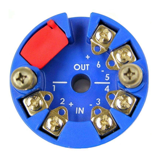
Page 5: Electrical Connections
(SEE NOTE 1) OPT SHIELD GROUND NOTE 1: DO NOT GROUND THE INPUT SENSOR IF UNIT IS CONNECTED TO A PC WITHOUT USING A USB ISOLATOR, OR IF CONNECTING EARTH GROUND AT TERMINAL 1. ______________________________________________________________________________________ Acromag, Inc. Tel:248-295-0880 Fax:248-624-9234 Email:sales@acromag.com http://www.acromag.com... -
Page 6: Output/Power Connections
WARNING: For compliance to applicable safety and performance standards, the use of twisted pair output wiring is recommended. Failure to adhere to sound wiring and grounding practices as instructed may compromise safety, performance, and possibly damage the unit. ______________________________________________________________________________________ Acromag, Inc. Tel:248-295-0880 Fax:248-624-9234 Email:sales@acromag.com http://www.acromag.com... -
Page 7: Earth Ground Connections
Note that most Personal Computers earth ground their USB ports and this makes contact with both the signal and shield grounds which is held in common to the input circuit ground. ______________________________________________________________________________________ Acromag, Inc. Tel:248-295-0880 Fax:248-624-9234 Email:sales@acromag.com http://www.acromag.com... -
Page 8: Usb Connections
(i.e. when non-insulated or grounded probes are used). You may use Acromag model USB-ISOLATOR to isolate your USB port, or you can optionally use another USB signal isolator that supports USB Full Speed operation (12Mbps). -
Page 9: Configuration Software
I/O Scaling: Select the input range endpoints to scale to the 4 to 20mA control to get a Help message output range endpoints. You can optionally set this up for a reverse- pertaining to the item you acting output by swapping the signals. pointed to. ______________________________________________________________________________________ Acromag, Inc. Tel:248-295-0880 Fax:248-624-9234 Email:sales@acromag.com http://www.acromag.com... -
Page 10: Troubleshooting
Personal USB isolator for this reason, and for Computer’s USB port. increased safety and noise immunity. Use an isolator like the Acromag USB- ISOLATOR. Otherwise, use a battery powered laptop to configure the transmitter which does not normally earth ground its USB port. - Page 11 USB cable to the transmitter. supply voltage is sufficient to USB has not enumerated Use the reset button on the Acromag USB supply over-scale current into the device. isolator to trigger renumeration of the the load (MIN 0.020*Rload),...
- Page 12 USB, check for a ground loop between a functioning transmitter be grounded T/C and earth ground of the returned to Acromag for repair, PC USB port. replacement, or re- programming. Acromag has Unit fails to operate or exhibits an output shift…...
-
Page 13: Technical Reference
USB signals be isolated when connected to a PC to prevent a ground loop from occurring between the PC earth ground and a grounded input sensor, which would have the negative affect of pulling the input bias supply to ground. ______________________________________________________________________________________ Acromag, Inc. Tel:248-295-0880 Fax:248-624-9234 Email:sales@acromag.com http://www.acromag.com... -
Page 14: Configuration Step-By-Step
Apply power to the transmitter output loop and always power the loop before connecting to USB. You will not be able to calibrate the unit without loop power applied. ______________________________________________________________________________________ Acromag, Inc. Tel:248-295-0880 Fax:248-624-9234 Email:sales@acromag.com http://www.acromag.com... - Page 15 Note (Table): Shaded cells refer to the calibration range end points used to calibrate the T/C type for this model. Bold column entries refer to the nominal T/C input range end points of this model. ______________________________________________________________________________________ Acromag, Inc. Tel:248-295-0880 Fax:248-624-9234 Email:sales@acromag.com http://www.acromag.com...
-
Page 16: Reconfiguration
Model ST133-16x0 Two-Wire T/C Transmitter w/USB ___________________________________________________________________ CONFIGURATION STEP-BY-STEP Reconfiguration After executing the Acromag Configuration software for this model, a screen similar to the one at right will appear, if you have not already connected to your transmitter via USB (note some fields are faded out under these conditions). - Page 17 Additionally, the device Product Name field HELP – You can press F1 for displays the Model, the Manufacturer field displays “Acromag, Inc.”, and the Help on a selected or Serial field displays this model’s serial number. Additionally, most of the highlighted field or control.
- Page 18 You can select the amount of filtering as None, Low, Medium, or High. Note the approximate response times indicated next to each filter level. ______________________________________________________________________________________ Acromag, Inc. Tel:248-295-0880 Fax:248-624-9234 Email:sales@acromag.com http://www.acromag.com...
- Page 19 Note that some under-range and over-range is built-into the unit, as the output can swing as low as 3.5Ma, and as high as 24Ma. Actual endpoint limits will vary slightly between units. ______________________________________________________________________________________ Acromag, Inc. Tel:248-295-0880 Fax:248-624-9234 Email:sales@acromag.com http://www.acromag.com...
-
Page 20: Zero & Full-Scale Calibration
CAUTION: Input signal levels outside of the nominal input range of the unit will not be accepted for configuration of zero or full-scale. Since not all input levels can be validated during field programming, connecting or entering incorrect signals will produce an undesired output response. ______________________________________________________________________________________ Acromag, Inc. Tel:248-295-0880 Fax:248-624-9234 Email:sales@acromag.com http://www.acromag.com... - Page 21 1. First, calibrate the TC Type J input range as shown above. 2. Connect a TC Type J ice point reference to the device input terminals. 3. Click on the “Tref-Cal” button. 4. In the pop-up box, click “OK”. ______________________________________________________________________________________ Acromag, Inc. Tel:248-295-0880 Fax:248-624-9234 Email:sales@acromag.com http://www.acromag.com...
-
Page 22: Other Configuration Controls
“No error encountered while reading configuration.” “No error encountered on read of input.” “Error encountered on read of input.” “Calibrating input zero, this takes several seconds.” “Error occurred during calibration, try again.” “Calibration successful.” ______________________________________________________________________________________ Acromag, Inc. Tel:248-295-0880 Fax:248-624-9234 Email:sales@acromag.com http://www.acromag.com... -
Page 23: Specifications
OFF. You can obtain form 8500-858 for specifying this calibration from our web site at www.acromag.com. Standard Models without custom calibration are instead calibrated by default to reference test conditions for T/C Type J, 0°C to 200°C mapped to 4 to... -
Page 24: Input
Break Detection: Can be selected for Upscale or Downscale open sensor or lead break detection. IMPORTANT: Calibration should be done with the break detection already set as required by the application, as changing it will affect current calibration somewhat. ______________________________________________________________________________________ Acromag, Inc. Tel:248-295-0880 Fax:248-624-9234 Email:sales@acromag.com http://www.acromag.com... - Page 25 32768. Actual resolution is constrained by the input range and its corresponding gain. An indication of relative input resolution is indicated by the number of parts between the calibration low and high endpoints shown in Table 4 below: ______________________________________________________________________________________ Acromag, Inc. Tel:248-295-0880 Fax:248-624-9234 Email:sales@acromag.com http://www.acromag.com...
-
Page 26: Output
CAUTION: Do not exceed 34VDC peak to avoid damage to the unit. Terminal voltage at or above 12V minimum must be maintained across the unit during operation. ______________________________________________________________________________________ Acromag, Inc. Tel:248-295-0880 Fax:248-624-9234 Email:sales@acromag.com http://www.acromag.com... -
Page 27: Usb Interface
Transmitter should be setup and configured in a safe environment only. Data Rate: USB v1.1 full-speed only, at 12Mbps. Up to 32K commands per second. USB 2.0 compatible. Consult the factory for legacy, low speed USB support (1.5Mbps) if required. ______________________________________________________________________________________ Acromag, Inc. Tel:248-295-0880 Fax:248-624-9234 Email:sales@acromag.com http://www.acromag.com... -
Page 28: Approvals
Case Material: Self-extinguishing polycarbonate ABS plastic, UL94 V-0 rated base material, color blue. USB dust cap material is Santoprene, 251-70W232, color red. Terminal Material: Captive 4-40 threaded steel screw and 0.040 inch thick Phosphor-Bronze terminal material. ______________________________________________________________________________________ Acromag, Inc. Tel:248-295-0880 Fax:248-624-9234 Email:sales@acromag.com http://www.acromag.com... -
Page 29: Environmental
5G-rms, 5-500 Hz, in 3 axis at 2 hours/axis per IEC60068-2-64. Mechanical Shock: 30g at 11ms half-sine shock pulses and 50g at 3ms half-sine shock pulses in each direction along 3 axis (18 shocks), per IEC60068-2-27. ______________________________________________________________________________________ Acromag, Inc. Tel:248-295-0880 Fax:248-624-9234 Email:sales@acromag.com http://www.acromag.com... -
Page 30: Reliability Prediction
All configuration information is stored in non-volatile memory. Refer to Configuration Step-by-Step in the Technical Reference section of this manual for detailed information on available software control of this model. ______________________________________________________________________________________ Acromag, Inc. Tel:248-295-0880 Fax:248-624-9234 Email:sales@acromag.com http://www.acromag.com... -
Page 31: Accessories
USB A-mini B Cable – Order 4001-113 USB A-mini B Cable 4001-113 This is a 1 meter, USB A-miniB replacement cable for connection between the USB isolator and the ST130 transmitter. It is normally included in ST13C-SIP. ______________________________________________________________________________________ Acromag, Inc. Tel:248-295-0880 Fax:248-624-9234 Email:sales@acromag.com http://www.acromag.com... - Page 32 Smart Transmitter to allow it to be snapped onto 35mm T-type DIN rail, or G-type DIN Rail. The screws and springs of this kit are identical to those provided in the Transmitter Mounting Kit ST130-MTG. ______________________________________________________________________________________ Acromag, Inc. Tel:248-295-0880 Fax:248-624-9234 Email:sales@acromag.com http://www.acromag.com...
- Page 33 Model ST133-16x0 Two-Wire T/C Transmitter w/USB __________________________________________________________________ Revision History The following table shows the revision history for this document: Release Date Version EGR/DOC Description of Revision 08 APR 2019 G FJM/ARP Added Long‐Term Stability/Recalibration section. 20 NOV 2019 H BC/ARP Correct the drawing on page 13; the drawing content is missing. _______________________________________________________________________________________ Acromag, Inc. Tel:248-295-0880 Fax:248-624-9234 Email:sales@acromag.com http://www.acromag.com...
Need help?
Do you have a question about the ST133-16 0 Series and is the answer not in the manual?
Questions and answers