Table of Contents
Advertisement
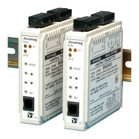
IntelliPack Series 801T
Transmitters and
Combination Transmitter/Alarms
mV/TC/RTD Input
USER'S MANUAL
ACROMAG INCORPORATED
30765 South Wixom Road
P.O. BOX 437
Wixom, MI 48393-7037 U.S.A.
Tel: (248) 295-0880
Fax: (248) 624-9234
Web: http://www.acromag.com
Email: sales@acromag.com
Copyright 1997, Acromag, Inc., Printed in the USA.
Data and specifications are subject to change without notice.
8500568J
Advertisement
Table of Contents

Related Manuals for Acromag IntelliPack 801T Series


Summary of Contents for Acromag IntelliPack 801T Series
- Page 1 ACROMAG INCORPORATED 30765 South Wixom Road P.O. BOX 437 Wixom, MI 48393-7037 U.S.A. Tel: (248) 295-0880 Fax: (248) 624-9234 Web: http://www.acromag.com Email: sales@acromag.com Copyright 1997, Acromag, Inc., Printed in the USA. Data and specifications are subject to change without notice. 8500568J...
-
Page 2: Table Of Contents
The information contained in this manual is subject to change Acromag, that this is the Buyer's responsibility. without notice. Acromag, Inc., makes no warranty of any kind with regard to this material, including, but not limited to, the implied warranties of merchantability and fitness for a particular 1.0 INTRODUCTION... -
Page 3: Key Intellipack 801T Features
IntelliPack Series 801T Transmitter/Alarm User's Manual mV/TC/RTD Input ___________________________________________________________________________________________ Key IntelliPack 801T Features…continued Front panel push buttons are available to reset a latched alarm • and to facilitate field configuration without connecting to a host Fully Isolated - Input, power, outputs, and relay contacts computer. -
Page 4: Accessory Items
For repairs to a product damaged in (please consult the factory). shipment, refer to the Acromag Service Policy to obtain return instructions. It is suggested that salvageable shipping cartons IntelliPack Configuration Software (Model 5030-881) and packing material be saved for future use in the event the product must be shipped. -
Page 5: Jumper Installation (For Voltage Output Only)
1. Power: Refer to Electrical Connections Drawing 4501-681. will require that the transmitter be reconfigured to suit your needs. Variations in power supply voltage within rated limits has This is accomplished with Acromag’s user-friendly Windows 95 negligible effect on module accuracy. For supply or NT Configuration Program and Serial Port Adapter. -
Page 6: Module Configuration
When depressing the push-buttons, use a blunt tipped object and apply pressure This transmitter/alarm module needs to be configured for gradually until you feel or hear the tactile response. your application. Configuration is done using Acromag’s Windows 95... -
Page 7: Theory Of Operation
The module will use the difference module. Please refer to Acromag’s Service Policy Bulletin or between the setpoint and dropout values to calculate relative contact Acromag for complete details on how to obtain service deadband. parts and repair. -
Page 8: Specifications
IntelliPack Series 801T Transmitter/Alarm User's Manual mV/TC/RTD Input ___________________________________________________________________________________________ In this case, use the Acromag IntelliPack Configuration Software INPUT SPECIFICATIONS to reconfigure the module and this will usually cure the problem. If the diagnostics continue to indicate a problem (a continuously... -
Page 9: Analog Output Specifications
IntelliPack Series 801T Transmitter/Alarm User's Manual mV/TC/RTD Input ___________________________________________________________________________________________ Thermocouple Reference: Accurate to better than 0.4C Table 6: Resolution/Minimum Span Per Input Range typical at 25C. Ambient temperature effect of the CJC is Range Resolution Minimum Span 0.01C/C typical. Note: The software configuration 15.6mV 0.78uV 1.56mV Min span... -
Page 10: Relay Output Specifications
IntelliPack Series 801T Transmitter/Alarm User's Manual mV/TC/RTD Input ___________________________________________________________________________________________ APPROVALS (-xxx0) General Output Specifications Digital-to-Analog Converter: Analog Devices AD420AR-32, 16-bit -. Agency Approvals - cULus Listed, UL File E199702. Integral Non-Linearity: 0.002% (1.4LSB) of span typical, 0.012% (7.9LSB) of span maximum, for ranges utilizing Warning: This product is not approved for hazardous location full output span (0-24mA, 0-10V DC). -
Page 11: Field Configuration And Controls
EIA232 serial ports. This port be scaled to 0% and 100% at the transmitter analog output. must be connected to the module through an Acromag The scaling may also be adjusted in-field via front panel IntelliPack Serial Port Adapter. - Page 12 IntelliPack Series 801T Transmitter/Alarm User's Manual mV/TC/RTD Input ___________________________________________________________________________________________ Visual Alarm Indicator: A yellow LED (labeled “RLY”) for the Transmitter - Computation: The following gives a brief description of current available transmitter transfer functions relay provides visual status indication of when the relay is in that can be applied to this model via the Configuration alarm (LED is ON in alarm).
-
Page 13: Simplified Schematic (4501-680)
IntelliPack Series 801T Transmitter/Alarm User's Manual mV/TC/RTD Input ___________________________________________________________________________________________ - 13 -... -
Page 14: Functional Block Diagram (4501-689)
IntelliPack Series 801T Transmitter/Alarm User's Manual mV/TC/RTD Input ___________________________________________________________________________________________ ON/OFF Counts Percent Alarm MODE L: 801T-1500 ONLY - 14 -... -
Page 15: Computer To Intellipack Connections (4501-643)
IntelliPack Series 801T Transmitter/Alarm User's Manual mV/TC/RTD Input ___________________________________________________________________________________________ - 15 -... -
Page 16: Electrical Connections (4501-681)
IntelliPack Series 801T Transmitter/Alarm User's Manual mV/TC/RTD Input ___________________________________________________________________________________________ RT N EXC+ RT N VOL TAGE OUTPUT J UM PER J M P T B3 T B 2 SHL D N. C. N. O. T B4 - 16 -... -
Page 17: Interposing Relay Conn. & Contact Pro. (4501-646)
IntelliPack Series 801T Transmitter/Alarm User's Manual mV/TC/RTD Input ___________________________________________________________________________________________ R TN JM P TB 2 TB 3 N . C . C O M N . O . TB 4 TB 1 AC L OAD DC L OAD - 17 -... -
Page 18: Enclosure Dimensions (4501-642)
IntelliPack Series 801T Transmitter/Alarm User's Manual mV/TC/RTD Input ___________________________________________________________________________________________ (118.9) 4.68 (95.3) 3.75 (59.4) 2.34 - 18 -... -
Page 19: Revision History
IntelliPack Series 801T Transmitter/Alarm User's Manual mV/TC/RTD Input ___________________________________________________________________________________________ REVISION HISTORY The following table details the revision history for this document: Release Date Version EGR/DOC Description of Revision 3-AUG-2017 CAP/JAA Remove CE Mark due to non-RoHS compliant part. Refer to ECN #17G016. - Page 20 IntelliPack Series 801T Transmitter/Alarm User's Manual mV/TC/RTD Input ___________________________________________________________________________________________ Notes: - 20 -...
Need help?
Do you have a question about the IntelliPack 801T Series and is the answer not in the manual?
Questions and answers