Table of Contents
Advertisement
Quick Links
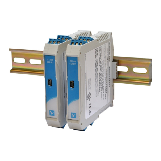
USB Programmable, DIN Rail Mount
Thin Transmitter
Model TT339-0700
Isolated 4-Wire Transmitter, Frequency/PWM/Pulse Input
Universal Current & Voltage Output
USER'S MANUAL
ACROMAG INCORPORATED
Tel: (248) 295-0880
30765 South Wixom Road
Fax: (248) 624-9234
Wixom, MI 48393-2417 U.S.A.
email: sales@acromag.com
Copyright 2014, Acromag, Inc., Printed in the USA.
8500-948M
Data and specifications are subject to change without notice.
Advertisement
Table of Contents

Subscribe to Our Youtube Channel
Related Manuals for Acromag TT339-0700


Summary of Contents for Acromag TT339-0700
- Page 1 Universal Current & Voltage Output USER’S MANUAL ACROMAG INCORPORATED Tel: (248) 295-0880 30765 South Wixom Road Fax: (248) 624-9234 Wixom, MI 48393-2417 U.S.A. email: sales@acromag.com Copyright 2014, Acromag, Inc., Printed in the USA. 8500-948M Data and specifications are subject to change without notice.
-
Page 2: Table Of Contents
Configuration ........................19 Calibration (Optional) ......................23 BLOCK DIAGRAM ..................24 How It Works ........................24 Flow Chart ......................... 25 Measurement Techniques ....................26 TROUBLESHOOTING ................26 Diagnostics Table ....................... 26 Service & Repair Assistance ....................27 Acromag, Inc. Tel: 248-295-0880 http://www.acromag.com... - Page 3 This is very important where property loss or human life is involved. It is important that you perform satisfactory overall system design and it is agreed between you and Acromag, that this is your responsibility.
-
Page 4: Getting Starteddescription
±20mA, 0–20mA, 4–20mA, ±10V, 0–10V, ±5V, and 0–5V. The output of this transmitter is unique in that it can drive either current or voltage under digital control using the same terminals. Acromag, Inc. Tel: 248-295-0880 http://www.acromag.com... -
Page 5: Mechanical Dimensions
DIN rail clip and use it as a lever to force the DIN rail spring clip down while pulling the bottom of the module outward until it disengages from the rail. Tilt the module upward to lift it from the rail. Acromag, Inc. Tel: 248-295-0880 http://www.acromag.com... -
Page 6: Electrical Connections
As a rule, output wires are normally separated from input wiring for safety, as well as for low noise pickup. Acromag, Inc. Tel: 248-295-0880 http://www.acromag.com... -
Page 7: Sensor Input Connections
TIP: Input, power, and output terminal blocks are a plug-in type and can be easily removed to facilitate module removal or replacement without removing individual wires. Acromag, Inc. Tel: 248-295-0880 http://www.acromag.com... - Page 8 Unipolar mode for non-zero crossing signals sensors are inherently connected to ground, use caution Internal pull-up/pull-down resistors are and avoid making additional ground connections which 2.7KΩ/1KΩ and connect to +5V/–FRTN could generate ground loops and measurement error. Acromag, Inc. Tel: 248-295-0880 http://www.acromag.com...
-
Page 9: Output Connections
1uF or larger capacitor directly across the load to reduce excessive ripple. For sensitive applications with high-speed acquisition at the load, high frequency noise may be reduced significantly by placing a 0.1uF capacitor directly across the load, as close to the load as possible. Acromag, Inc. Tel: 248-295-0880 http://www.acromag.com... -
Page 10: Power Connections
This transmitter is powered from 12–32VDC (36VDC peak) by connecting power as shown below. This transmitter can be optionally powered (or redundantly powered) via the DIN rail bus when coupled to the DIN rail bus connector (Acromag Model 1005-063) and a bus terminal block (Acromag 1005-220 or 1005-221). This optional method can allow several modules to share a single power supply without wiring to each individually. -
Page 11: Optional Bus & Redundant Power Connections
Important – End Stops: If this module uses the optionally powered (or redundantly powered) via the DIN rail bus for hazardous location installations (Class I, Division 2 or ATEX Zone 2) it must use two end stops (Acromag 1027-222) to secure the terminal block and module (not shown). -
Page 12: Earth Ground Connections
(PC USB ports are commonly earth grounded and make contact with both the USB signal and shield ground which is held in common to the input circuit ground of the transmitter). Acromag, Inc. Tel: 248-295-0880 http://www.acromag.com... -
Page 13: Usb Connections
(i.e. when non-insulated or grounded The intent of mating USB with this sensors are used). Acromag model USB-ISOLATOR may be used to isolate the USB transmitter is so that it can be port, or optionally a different USB signal isolator that supports USB Full Speed conveniently configured and operation (12Mbps). -
Page 14: Configuration Software
CONFIGURATION SOFTWARE Quick Overview – Android This transmitter can be configured and calibrated via the Acromag Agility™ Config Tool App. This software can be downloaded free of charge from the Google Play store at play.google.com. To connect to this transmitter, a USB OTG (On-The-Go) cable (Acromag 5028-565) and USB A to Mini-B cable (Acromag 4001-113) are required. -
Page 15: Quick Overview - Windows
USB connection to a PC or laptop. The configuration software can be downloaded free of charge from our web site at www.acromag.com. This software is also included on a CD-ROM bundled with the Configuration Kit TT-SIP (see Accessories). For this transmitter, use program “TT339 Config.exe”. - Page 16 Help Calibration Status (Bottom of Window) message pertaining to the item you The Calibration Status bar at the bottom of the window will display status pointed to. messages relative to calibration. Acromag, Inc. Tel: 248-295-0880 http://www.acromag.com...
-
Page 17: Operation Step-By-Step
Now that you have made your connections and applied power, you can execute the “TT339 Config.exe” software to begin configuration of the transmitter (software is compatible with XP or later versions of the Windows operating system). Acromag, Inc. Tel: 248-295-0880 http://www.acromag.com... - Page 18 You will not be able to configure, calibrate, or test the transmitter without power applied. After executing the Acromag Configuration software for this transmitter, the window shown at left will appear, if you have not already connected to the transmitter via USB (note fields are blank under these conditions).
-
Page 19: Configuration
WARNING: Do not exceed 15VDC with the internal pull-up or pull- down resistors enabled, or damage to the circuit will result. Limit internal pull-up/pull-down resistor power to less than 0.25W. Disable the Pull-up/Pull-down if the input to the transmitter is AC mains voltage (120V Acromag, Inc. Tel: 248-295-0880 http://www.acromag.com... - Page 20 NOTE: Debounce is useful for filtering out temporary signal glitches such as those generated by contact relays. For best results, set the Debounce to twice the expected duration of contact bounce. Acromag, Inc. Tel: 248-295-0880 http://www.acromag.com...
- Page 21 Note: Approximately 5% under-range and over-range is built into each output range selection. If the I/O Scaling Zero-Scale and Full-Scale points are chosen too close together, performance will be degraded. Acromag, Inc. Tel: 248-295-0880 http://www.acromag.com...
- Page 22 (See Specifications Reference Test Conditions). This does not restore calibration, only configuration. Alternately, this control can be used as a sanitation tool to restore the transmitter to its initial configuration. Acromag, Inc. Tel: 248-295-0880 http://www.acromag.com...
-
Page 23: Calibration (Optional)
NOTE: To measure current, you can alternatively connect a voltmeter across a precision load resistor, and then accurately read the output current as a function of the IR voltage drop produced in the resistor (recommended for current outputs). Acromag, Inc. Tel: 248-295-0880 http://www.acromag.com... -
Page 24: Block Diagram
EXC_EN BOOST REG. CONVERTER ISOLATED POWER ISOLATED FLYBACK CONVERTER BUS CONN OUTPUT POWER +15V TT339-0700 SIMPLIFIED SCHEMATIC FLYBACK ISOLATED OUTPUT CIRCUIT CONVERTER (FILTERING AND DETAIL OMITTED FOR CLARITY) 12-32V FREQUENCY OR PULSE INPUT INPUT POWER ISOLATED POWER How It Works... -
Page 25: Flow Chart
Count Cumulative since Cumulative Moving Moving Average* previous Average (CMA) Output Update Update Output based on scaled Measurement Using Switch to Measurement Technique A? Technique B > 25KHz? Switch to Measurement Technique A < 20KHz? Acromag, Inc. Tel: 248-295-0880 http://www.acromag.com... -
Page 26: Measurement Techniques
USB via a USB isolator for this reason, and for grounded input sensor increased safety and noise immunity. Use an isolator and earth ground at the like the Acromag USB-ISOLATOR. Otherwise, use a connected PC’s USB battery powered laptop to configure the transmitter port. -
Page 27: Service & Repair Assistance
Its enclosure is not meant to be opened for access and can be damaged easily if snapped apart. It is highly recommended that a non-functioning transmitter be returned to Acromag for repair or replacement. Acromag has automated test equipment that thoroughly checks and calibrates the performance of each transmitter, and can restore firmware. -
Page 28: Accessories
This is a 1 meter, USB A-miniB replacement cable for connection between the USB isolator and the transmitter. It is normally included in the TTC-SIP. Note that software for all TT Series models is available free of charge, online at www.acromag.com. Acromag, Inc. Tel: 248-295-0880 http://www.acromag.com... -
Page 29: Usb Otg Cable
USB OTG Cable 5028-565 This is a 6 inch, USB On-The-Go cable for connection between the USB A-mini B Cable and a mobile phone or tablet. It is required to use the Acromag Agility™ Config Tool App. Note that the Acromag Agility ™ Config Tool is available free of charge, online at the Google Play store. -
Page 30: Specifications
Disable Pull- up/Pull-Down if transmitter input is AC mains voltage (120V Input Excitation Supply: +5VDC, current limited to +20mA typical. Bipolar Transient Voltage Suppressor (TVS) clamps level to ±5.6V typical. Input Impedance: 37.2KΩ, typical. Acromag, Inc. Tel: 248-295-0880 http://www.acromag.com... - Page 31 0Hz to 50000Hz 100ms 1 part in 3200000 ±10Hz 1000ms 1 part in 32000000 ±1Hz 10ms 1 part in 320000 ±200Hz 0Hz to 100000Hz 100ms 1 part in 3200000 ±20Hz 1000ms 1 part in 32000000 ±2Hz Acromag, Inc. Tel: 248-295-0880 http://www.acromag.com...
-
Page 32: Output
Output Update: Adjustable from 10ms to 5000ms. Determines the rate at which the output signal is updated. Output Settling Time: 2.8ms, 0% to 98% for a step change in input, typical. Acromag, Inc. Tel: 248-295-0880 http://www.acromag.com... - Page 33 Output Ripple: Less than ±0.1% of output span. Output Ambient Temperature Drift: Includes the combined effects of zero and span drift over temperature and is typically better than ±40ppm/°C (±0.0040%/°C) over the ambient temperature range for reference test conditions (see Input Specifications). Acromag, Inc. Tel: 248-295-0880 http://www.acromag.com...
-
Page 34: Usb Interface
92mA Typical / 101mA Max transmitter during operation. 76mA Typical / 84mA Max 44mA Typical / 48mA Max 33mA Typical / 36mA Max Power Supply Effect: Less than ±0.001% of output span effect per volt DC change. Acromag, Inc. Tel: 248-295-0880 http://www.acromag.com... -
Page 35: Enclosure & Physical
Shock & Vibration Immunity: Conforms to: IEC 60068-2-6: 10-500 Hz, 4G, 2 Hours/axis, for sinusoidal vibration; IEC 60068-2-64: 10-500 Hz, 4G-rms, 2 Hours/axis, for random vibration, and IEC 60068-2-27: 25G, 11ms half-sine, 18 shocks at 6 orientations, for mechanical shock. Acromag, Inc. Tel: 248-295-0880 http://www.acromag.com... - Page 36 Telecom / Network Port, per CISPR 22 WARNING: This is a Class A product. In a domestic environment, this product may cause radio interference in which the user may be required to take adequate measures. Acromag, Inc. Tel: 248-295-0880 http://www.acromag.com...
-
Page 37: Agency Approvals
Consult Factory. ATEX Certified: Model TT339-0700 is ATEX Certified for Explosive Atmospheres per ATEX Directive 94/9/EC which complies with standards BS EN 60079-0:2012 & BS EN 60079-15:2010. -
Page 38: Revision History
Added cULus Mark to this model (removed pending). 31-JUL-2014 CAP/ARP Added UL caution symbols / statements. 4-NOV-2014 JEB/ARP Added Acromag Agility™ Config Tool Quick Guide. Added USB OTG cable in Accessories Section. 15-OCT-2015 CAP/ARP Added ATEX symbols / statements. Acromag, Inc. Tel: 248-295-0880...
Need help?
Do you have a question about the TT339-0700 and is the answer not in the manual?
Questions and answers