Table of Contents
Advertisement
Quick Links
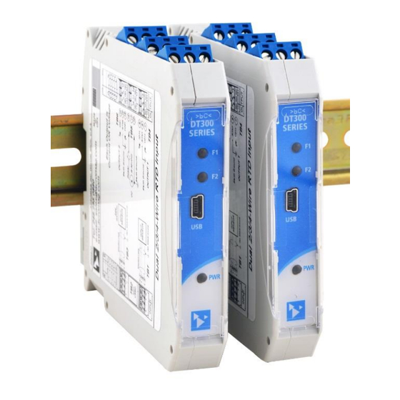
USB Programmable, DIN Rail Mount, DC-Powered
Dual/Single Transmitter or Signal Splitter w/ Millivolt/
Thermocouple Inputs & Current or Voltage Outputs
Model DT333-0700, Dual Input Transmitter for
Thermocouple and ±100mV/±1V Input
USER'S MANUAL
ACROMAG INCORPORATED
Tel: (248) 295-0880
30765 South Wixom Road
Wixom, MI 48393-2417 U.S.A.
email: sales@acromag.com
Copyright 2018, Acromag, Inc., Printed in the USA.
8501130C
Data and specifications are subject to change without notice.
Advertisement
Table of Contents

Related Manuals for Acromag DT333-0700


Summary of Contents for Acromag DT333-0700
- Page 1 Model DT333-0700, Dual Input Transmitter for Thermocouple and ±100mV/±1V Input USER’S MANUAL ACROMAG INCORPORATED Tel: (248) 295-0880 30765 South Wixom Road Wixom, MI 48393-2417 U.S.A. email: sales@acromag.com Copyright 2018, Acromag, Inc., Printed in the USA. 8501130C Data and specifications are subject to change without notice.
-
Page 2: Table Of Contents
USB A-mini B Cable ......................28 USB OTG Cable ........................29 DIN Rail Bus Connector Kit ....................29 End Stops........................... 29 SPECIFICATIONS ....................30 Model Number ........................30 Input (Each) ........................30 Acromag, Inc. Tel: 248-295-0880 - 2 - - 2 - https://www.acromag.com http://www.acromag.com... - Page 3 This is very important where property loss or human life is involved. It is important that you perform satisfactory overall system design and it is agreed between you and Acromag, that this is your responsibility.
-
Page 4: Getting Started
DESCRIPTION Symbols on equipment: Each I/O channel of the DT333-0700 is modeled after an ANSI/ISA Type IV transmitter. Isolated input channels interface with thermocouple sensors (type J, K, T, R, S, B, E or N) or ±100mV/±1V signal sources and modulate isolated DC outputs that may drive current or voltage. -
Page 5: Mechanical Dimensions
DIN rail clip and use it as a lever to force the DIN rail spring clip down while pulling the bottom of the module outward until it disengages from the rail. Then simply lift it from the rail. Acromag, Inc. Tel: 248-295-0880 - 5 - - 5 - https://www.acromag.com... -
Page 6: Electrical Connections
Use adequate wire insulation and follow proper wiring practice, as common mode voltages can exist on signal wiring. As a rule, output wires are normally separated from input wiring for safety, as well as for low noise pickup. Acromag, Inc. Tel: 248-295-0880 - 6 - - 6 - https://www.acromag.com... -
Page 7: Sensor Input Connections
The positive input is on the left and labeled “+”, and the negative input is to its right. See connection figure below per input model. Each output channel may drive current or voltage from separate channel terminals that share a return. Acromag, Inc. Tel: 248-295-0880 - 7 - - 7 - https://www.acromag.com... -
Page 8: Output Connections
For sensitive applications with high-speed acquisition at the load, high frequency noise may be reduced significantly by placing a 0.1uF capacitor directly across the load, and as close to the load as possible. Acromag, Inc. Tel: 248-295-0880 - 8 - - 8 - https://www.acromag.com... -
Page 9: Power Connections
This transmitter can be optionally powered (or redundantly powered) via polarity protected. the DIN rail bus when coupled to an optional DIN rail bus connector (Acromag Model 1005-063) with a bus terminal block (Acromag 1005-220 or 1005-221). This IMPORTANT – External Fuse: If... -
Page 10: Optional Bus Power Connections
24 units safely. powered) via the DIN rail bus for hazardous location installations (Class I, Division 2 or ATEX/IECEx Zone 2) it should use two end stops (like Acromag 1027-222) to secure the terminal block and module (not shown). -
Page 11: Earth Ground Connections
(A PC commonly earth grounds its USB port contacting both the USB signal and shield ground which are held in common to the input circuit ground of this transmitter). Acromag, Inc. Tel: 248-295-0880 - 11 - - 11 - https://www.acromag.com... -
Page 12: Usb Connections
Windows-based PC connected to the unit via USB (Windows 7 or later required), or via a USB-OTG connection to an Android smartphone or tablet using the Acromag Agility mobile app. Refer to the following drawing to connect your PC or laptop to the transmitter to reconfigure or calibrate it using this software. -
Page 13: Configuration Software
4-Wire mV/TC Dual Transmitter w/USB CONFIGURATION SOFTWARE Quick Overview – Android This dual transmitter can be setup & calibrated via the Acromag Agility™ Config Tool. The Agility™ software APP can be downloaded free of charge from play.google.com. To connect to this transmitter, a USB OTG (On-The-Go) cable (5028-565) and USB A to Mini-B cable (4001-113) are required. -
Page 14: Quick Overview - Windows
Communication Set up, Configuration, Calibration, and Diagnostics. A short description of each of these configuration pages follows: Communication Set up (First Connect to Unit Here) Click “Open” to connect to the DT333-0700 and your • Select from connected transmitters and screen will like: Open/Close communication with them. - Page 15 Help message pertaining to the item you pointed to. Acromag, Inc. Tel: 248-295-0880 - 15 - - 15 - https://www.acromag.com...
- Page 16 Calibration Status (Bottom of Calibration Screen)... • Displays communication status messages relative to the calibration process. Acromag, Inc. Tel: 248-295-0880 - 16 - - 16 - https://www.acromag.com http://www.acromag.com...
-
Page 17: Operation Step-By-Step
Now that you have made your connections and applied power, you can execute the DT333Config.exe software to begin configuration of the unit (software is compatible with v7 or later versions of the Windows operating system). Acromag, Inc. Tel: 248-295-0880 - 17 - - 17 - https://www.acromag.com... -
Page 18: Thermocouple Millivoltage Versus Temperature Reference Table
TB1 and TB3 terminals to cold-junction compensate its T/C reading at channel 1 or channel 2 and remove the portion of the measured voltage that corresponds to its cold junction. Acromag, Inc. Tel: 248-295-0880 - 18 - - 18 - https://www.acromag.com... -
Page 19: Configuration
After executing the Acromag Configuration software for this model, the first screen shown at left will appear, if you have not already connected to your transmitter via USB (note fields are blank under these conditions). - Page 20 Higher filter levels result in lower average noise, but with a slower I/O response time (see Specifications for detail). Acromag, Inc. Tel: 248-295-0880 - 20 - - 20 - https://www.acromag.com...
- Page 21 Status of your sent message to the unit in the “Status” field. Alternately, you could click “File” in the upper left corner to save the settings to a file on your PC, for later reference. Acromag, Inc. Tel: 248-295-0880 - 21 - - 21 - https://www.acromag.com...
-
Page 22: Calibration (Optional)
Since input levels cannot be validated during calibration, incorrect signal levels will produce an undesired output response. Acromag, Inc. Tel: 248-295-0880 - 22 - - 22 - https://www.acromag.com... - Page 23 Channel 2 reference. You will be prompted to connect a TC Type J ice point reference to input 1 or 2 depending on the Channel. Follow the on-screen instructions to complete CJC calibration. Acromag, Inc. Tel: 248-295-0880 - 23 - - 23 - https://www.acromag.com...
-
Page 24: Diagnostics
Note the simulated lamp next to the button flashes slowly each time it samples the inputs. Click [Stop Polling] to stop polling the inputs before moving onto another tab/page. Acromag, Inc. Tel: 248-295-0880 - 24 - - 24 - https://www.acromag.com... -
Page 25: Block Diagram
PC to prevent a ground loop from occurring between the PC earth ground and a grounded input 1 sensor, which would have the negative effect of pulling the input bias supply to ground and clipping any negative range. Acromag, Inc. Tel: 248-295-0880 - 25 - - 25 - https://www.acromag.com... -
Page 26: Troubleshooting
Bad USB Connection Recheck USB Cable Connection. Acromag’s Application Engineers USB has not enumerated the Use the reset button of the Acromag USB can provide further technical device. isolator to trigger re-numeration of the assistance if required. Repair... -
Page 27: Service & Repair Assistance
Please refer to Acromag’s Service Policy and Warranty Bulletin, or you may contact Acromag for complete details on how to obtain repair or replacement. Acromag, Inc. Tel: 248-295-0880... -
Page 28: Accessories
This is a 1 meter, USB A-miniB replacement cable for connection between the USB isolator and the DT/TT/SP transmitter. It is normally included in TTC-SIP. Note that software for all TT/DT/SP Series models is available free of charge, online at www.acromag.com. Acromag, Inc. Tel: 248-295-0880 - 28 - - 28 - https://www.acromag.com... -
Page 29: Usb Otg Cable
USB OTG Cable 5028-565 This is a 6-inch, USB On-The-Go cable for connection between the USB A-mini B Cable and a mobile phone or tablet. It is required to use the Acromag Agility™ Config Tool App. Note that the Acromag Agility ™ Config Tool is available free of charge, online at the Google Play store. -
Page 30: Specifications
Inaccuracy with CJC enabled may increase by as much as 0.5C during the post power-on warm-up period and will be 0.2C typical after reaching thermal equilibrium in about five minutes. Acromag, Inc. Tel: 248-295-0880 - 30 - - 30 - https://www.acromag.com... - Page 31 Note: At medium and high filter settings, the heavily attenuated 60Hz signal cannot be measured due to 4 order filtering by the input ADC which adds 80dB minimum of rejection at frequencies between 47Hz and 61Hz. Acromag, Inc. Tel: 248-295-0880 - 31 - - 31 - https://www.acromag.com...
- Page 32 Likewise, error in degrees is magnified as the input span is reduced. Rated performance is based on a 10mV minimum input span and 12-bits minimum resolution. Acromag, Inc. Tel: 248-295-0880 - 32 - - 32 - https://www.acromag.com...
-
Page 33: Output (Each)
NONE 13ms 38ms MEDIUM 122ms HIGH 1158ms Output Load: The voltage output can drive loads down to 1KΩ minimum. The current output can drive 21mA DC into 0-525Ω. Acromag, Inc. Tel: 248-295-0880 - 33 - - 33 - https://www.acromag.com http://www.acromag.com... -
Page 34: Usb Interface
57mA Typical / 63mA Max operation. 44mA Typical / 48mA Max Power Supply Effect: Less than 0.001% of output span effect per volt DC change. Acromag, Inc. Tel: 248-295-0880 - 34 - - 34 - https://www.acromag.com http://www.acromag.com... -
Page 35: Enclosure & Physical
5) Conducted RF Immunity (CRFI), per IEC 61000-4-6. This is a Class B Product with Emissions per BS EN 61000-6-3: 1) Enclosure Port, per CISPR 16. 2) Low Voltage AC Mains Port, per CISPR 14, 16. Acromag, Inc. Tel: 248-295-0880 - 35 - - 35 - https://www.acromag.com... -
Page 36: Agency Approvals
Refer to Operation Step-By-Step in the Technical Reference section of this manual for detailed information on available software control of this model. Acromag, Inc. Tel: 248-295-0880 - 36 - - 36 - https://www.acromag.com... -
Page 37: Revision History
11 DEC 2018 BC/ARP Initial Release. 15 SEP 2020 CAP/ARP Added cULus, ATEX, IECEx, and FCC approvals. Added Altitude: Up to 2000 meters (Environmental 28 JAN 2022 CAP/AMM Section) Acromag, Inc. Tel: 248-295-0880 - 37 - - 37 - https://www.acromag.com http://www.acromag.com...
Need help?
Do you have a question about the DT333-0700 and is the answer not in the manual?
Questions and answers