Table of Contents
Advertisement
Quick Links
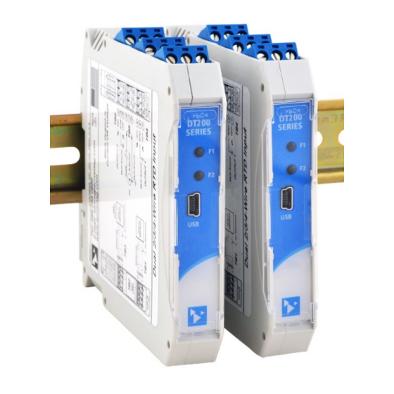
Model DT233-0600
USB Programmable, DIN Rail Mounted Transmitter,
w/ Dual Isolated Thermocouple/millivoltage Inputs,
and Passive 4-20mA Loop-Powered Outputs,
USER'S MANUAL
ACROMAG INCORPORATED
30765 South Wixom Road
Wixom, MI 48393-2417 U.S.A.
Copyright 2018, Acromag, Inc., Printed in the USA.
Data and specifications are subject to change without notice.
Tel: (248) 295-0880
email: sales @acromag.com
8501128E
Advertisement
Table of Contents

Related Manuals for Acromag DT233-0600


Summary of Contents for Acromag DT233-0600
- Page 1 Passive 4-20mA Loop-Powered Outputs, USER’S MANUAL ACROMAG INCORPORATED Tel: (248) 295-0880 30765 South Wixom Road email: sales @acromag.com Wixom, MI 48393-2417 U.S.A. Copyright 2018, Acromag, Inc., Printed in the USA. 8501128E Data and specifications are subject to change without notice.
-
Page 2: Table Of Contents
BLOCK DIAGRAM ..................... 29 How It Works ........................29 TROUBLESHOOTING ..................30 Diagnostics Table ....................... 30 Service & Repair Assistance ....................32 ACCESSORIES ....................33 Software Interface Package ....................33 Acromag, Inc. Tel: 248-295-0880 - 2 - - 2 - https://www.acromag.com http://www.acromag.com... - Page 3 This is very important where property loss or human life is involved. You must perform satisfactory overall system design and it is agreed between you and Acromag, that this is your responsibility. The information of this manual may change without notice. Acromag makes no warranty of any kind regarding this material, including, but not limited to, the implied warranties of merchantability and fitness for a particular purpose.
-
Page 4: Getting Started Description
GETTING STARTED DESCRIPTION Symbols on equipment: The DT233-0600 Dual Transmitter provides two isolated ANSI/ISA Type II transmitter channels for thermocouple/mV input signals that drive two isolated loop-powered passive current outputs. This model interfaces with thermocouple Type J, K, T, R, S, B, E, N, or ±100mV input signals at separately isolated inputs, and modulates two isolated 2-wire current loops proportional to their respective input. -
Page 5: Application
75VDC or 50VAC. Acromag, Inc. Tel: 248-295-0880 - 5 - - 5 - https://www.acromag.com http://www.acromag.com... -
Page 6: Din Rail Mounting & Removal
DIN rail clip and use it as a lever to force the DIN rail spring clip down while pulling the bottom of the module outward until it disengages from the rail. Then simply lift it from the rail. Acromag, Inc. Tel: 248-295-0880 - 6 - - 6 - https://www.acromag.com... -
Page 7: Electrical Connections
Important – End Stops: For hazardous location installations (Class I, Division 2 or ATEX/IECEx Zone 2), it should utilize two end stops (like Acromag 1027-222) to help secure modules to the DIN rail (not shown). -
Page 8: Output/Power Connections
Earth ground is normally applied at the loop power supply minus terminal. Each 2-wire transmitter output varies off this ground by the voltage drop in the load resistance and lead-wire of the loop. Acromag, Inc. Tel: 248-295-0880 - 8 - - 8 - https://www.acromag.com... - Page 9 “sinking” inputs, and these require that a separate power supply connect within the loop. These types of receivers are depicted in the figures on the next two pages. Acromag, Inc. Tel: 248-295-0880 - 9 - - 9 - https://www.acromag.com...
- Page 10 (such as an I/P current-to-pressure transducer), this may reduce output stability. In this case, place a 0.1uF capacitor directly across the inductive load(s) and this will typically cure the problem. Acromag, Inc. Tel: 248-295-0880 - 10 - - 10 - https://www.acromag.com...
-
Page 11: Earth Ground Connections
Acromag, Inc. Tel: 248-295-0880 - 11 - - 11 - https://www.acromag.com... -
Page 12: Usb Connections
USB connection (See Output/Power Connections). • USB Signal Isolation is Required (See Below) - You may use Acromag model USB-ISOLATOR to isolate your USB port, or you can optionally use another USB signal isolator that supports USB Full Speed operation (12Mbps). -
Page 13: Configuration Software
“Wiring Diagram”. You may swipe left or right to view more diagrams. The main screen also has three icons across the top: an Acromag logo w/connected model indicated, a question mark, a gear icon, and three vertical dots. These icons access additional features of this software as... - Page 14 Optionally, you can review an online video tutorial on working with the unit by tapping the Video Tutorial URL line. Or, if you wish to contact Acromag for assistance, you can tap the [CONTACT ACROMAG] bar to obtain the phone and email information window shown below for talking to Acromag directly (the same information is also obtained via the menu dotted action bar icon and “Contact Acromag”...
- Page 15 If you tap the right-most dotted Menu icon of the action bar at the top right of your screen, you will get a selection menu for “About” information on this software application, and “Contact Acromag” for contact information, both shown at left Below the icons of the top line are file three tabs: Configuration, Calibration, and Diagnostic Center, each of which are described in the following pages.
- Page 16 ADC level to its input range full-scale (100%). The device status at the bottom of the page will report if the calibration was sent successfully. Acromag, Inc. Tel: 248-295-0880 - 16 - - 16 - https://www.acromag.com...
- Page 17 When rescaling I/O, make sure that you have adequate I/O span, as “too-tight” input or output spans will have diminished resolution and magnify error. Acromag, Inc. Tel: 248-295-0880 - 17 - - 17 - https://www.acromag.com...
- Page 18 Check the “Save Data” box if you wish to log the polled values to a CSV (Comma Separated Value) data file for reference. Note the Communication Status of the device is indicated at the bottom of the screen. Acromag, Inc. Tel: 248-295-0880 - 18 - - 18 - https://www.acromag.com...
-
Page 19: Quick Overview - Windows
Software and a USB connection to a Windows PC or laptop. The configuration software can be downloaded free of charge from our web site at https://www.acromag.com. This software is also included on a CDROM bundled with the Configuration Kit TTC-SIP Click “Open”... - Page 20 Calibration Status (Bottom of Screen) • Displays communication status messages for the calibration process. The CALIBRATION STATUS field at the bottom of the screen will display status messages relative to calibration. Acromag, Inc. Tel: 248-295-0880 - 20 - - 20 - https://www.acromag.com http://www.acromag.com...
-
Page 21: Operation Step-By-Step
PC using a USB isolator and cables provided in the Configuration Kit TT-SIP. Optionally, you could instead connect the unit to an Android smartphone or tablet running the Agility mobile app with a USB- OTG cable. Acromag, Inc. Tel: 248-295-0880 - 21 - - 21 - https://www.acromag.com... -
Page 22: Thermocouple Millivoltage Versus Temperature Reference Table
(usually referred to as its Cold Junction reading). This unit senses the temperature of its TB1 and TB3 terminals to cold-junction compensate its T/C readings and remove the portion of the measured voltages that correspond to their cold junctions. Acromag, Inc. Tel: 248-295-0880 - 22 - - 22 - https://www.acromag.com... -
Page 23: Setup Communication
Model DT233-0600 Dual Two-Wire mV/TC Input Transmitters Setup Communication After executing the Acromag Configuration software for your model, a screen like that shown at left will appear if you have not already connected to your transmitter via USB (note fields are blank and red status message appears). -
Page 24: Configuration
I/O response time varies with input filter selection and typical times are indicated in parenthesis next to filter selection. Higher filter levels result in lower average noise, but with a slower I/O response time (see Specifications for detail). Acromag, Inc. Tel: 248-295-0880 - 24 - - 24 - https://www.acromag.com... - Page 25 “Calibrate” tab to calibrate this could click “File” in the upper left corner to save the settings to a file unit’s inputs, outputs, or temperature on your PC, for later reference. references. Acromag, Inc. Tel: 248-295-0880 - 25 - - 25 - https://www.acromag.com http://www.acromag.com...
-
Page 26: Calibration (Optional)
Once you input full-scale precisely, click the [OK] button of the prompt to calibrate full-scale and then follow the on-screen prompt. Acromag, Inc. Tel: 248-295-0880 - 26 - - 26 - https://www.acromag.com... - Page 27 This field displays calibration status messages like “No Error”, “Transfer Error”, and “Timeout Error” during calibration. If you encounter a Transfer or Timeout Error, you should repeat the calibration process. Acromag, Inc. Tel: 248-295-0880 - 27 - - 27 - https://www.acromag.com...
-
Page 28: Diagnostics
COMMUNICATION STATUS This field displays communication status messages like “No Error”, “Transfer Error”, and “Timeout Error” which may be encountered during polling. Acromag, Inc. Tel: 248-295-0880 - 28 - - 28 - https://www.acromag.com http://www.acromag.com... -
Page 29: Block Diagram
1 bias supply to ground, clipping the negative portion of the bipolar input 1 range. Acromag, Inc. Tel: 248-295-0880 - 29 - - 29 - https://www.acromag.com... -
Page 30: Troubleshooting
Verify that power is applied to the USB has not enumerated the Use the reset button on the Acromag USB loop and that your loop power device. isolator to trigger renumeration of the... - Page 31 Acromag, Inc. Tel: 248-295-0880 - 31 - - 31 - https://www.acromag.com http://www.acromag.com...
-
Page 32: Service & Repair Assistance
Acromag has automated test equipment that thoroughly checks and calibrates the performance of each transmitter and can restore firmware. Please refer to the Acromag Service Policy and Warranty Bulletin, or you may contact Acromag for complete details on how to obtain repair or replacement. -
Page 33: Accessories
This is a 1 meter, USB A-miniB replacement cable for connection between the USB isolator and the TT/SP transmitter/splitter. It is normally included in TT-SIP. Note that software for all TT/SP Series models is available free of charge, online at www.acromag.com. Acromag, Inc. Tel: 248-295-0880 - 33 - - 33 - https://www.acromag.com... -
Page 34: Accessories
Cable and an Android mobile phone or tablet that support USB. It is required to use the Acromag Agility™ Config Tool App for Android OS reconfiguration of this transmitter. Note that the Acromag Agility ™ Config Tool is available free of charge, online at the Google Play store. End Stops Two End Stops –... -
Page 35: Specifications
The DT model prefix denotes Dual Transmitter. The 3 digit “2” denotes a member Model DT233-0600 of the Acromag DT200 2-wire loop-powered Transmitter family. The trailing 33 Dual isolated mV/TC Inputs denotes a thermocouple/millivoltage input type. The “-0600” model suffix specifies a (J, K, T, E, R, S, B, N, or ±100mV),... - Page 36 4mA and 20mA at the output. Input resolution decreases and potential error magnifies when your programmed input range is reduced. Nominal rated ±0.1% error assumes a minimum input span of 10mV. Acromag, Inc. Tel: 248-295-0880 - 36 - - 36 - https://www.acromag.com...
- Page 37 The effective I/O resolution for a given range will be the lowest resolution of the A/D (see below), or its linearized value (using 0.05C intervals), as D/A resolution is always greater. Acromag, Inc. Tel: 248-295-0880 - 37 - - 37 - https://www.acromag.com...
-
Page 38: Outputs (Each)
Table 4: Output DAC Current Level & Digital DAC Count I-LOOP = 24mA*COUNT/65536 COUNT = 65536*I-LOOP/24mA 3.7mA 10103 4.0mA 10923 12mA 32768 20mA 54613 20.7mA 56525 23.9996mA 65535 Acromag, Inc. Tel: 248-295-0880 - 38 - - 38 - https://www.acromag.com http://www.acromag.com... -
Page 39: Usb Interface
Driver: No special drivers required. Uses the built-in USB Human Interface Device (HID) drivers of the Windows Operating System (Windows XP or later versions only). USB Connector: 5-pin, Mini USB B-type socket, HiRose UX60SC-MB-5S8(80). Acromag, Inc. Tel: 248-295-0880 - 39 - - 39 - https://www.acromag.com... -
Page 40: Enclosure & Physical
OFF is normal, blinks for fault, or blinks once if the loop power is lost or the loop is opened. Acromag, Inc. Tel: 248-295-0880 - 40 - - 40 - https://www.acromag.com... -
Page 41: Environmental
5) Conducted RF Immunity (CRFI), per IEC 61000-4-6. This is a Class B Product with Emissions per BS EN 61000-6-3: 1) Enclosure Port, per CISPR 16. 2) Low Voltage AC Mains Port, per CISPR 14, 16. Acromag, Inc. Tel: 248-295-0880 - 41 - - 41 - https://www.acromag.com... -
Page 42: Agency Approvals
OFF is normal and LED will blink once if loop power is lost or the loop is opened. Acromag, Inc. Tel: 248-295-0880 - 42 - - 42 - https://www.acromag.com... -
Page 43: Revision History
15 SEP 2020 CAP/ARP Added cULus, ATEX, IECEx, and FCC approvals. 28 JAN 2022 CAP/AMM Added Altitude: Up to 2000 meters (Environmental Section) 11-OCT-2022 Removed remnant mention of voltage/current inputs. Acromag, Inc. Tel: 248-295-0880 - 43 - - 43 - https://www.acromag.com http://www.acromag.com...
Need help?
Do you have a question about the DT233-0600 and is the answer not in the manual?
Questions and answers