Table of Contents
Advertisement
Quick Links
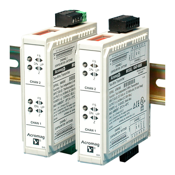
Series 655T/656T
Single/Dual Channel Two-Wire Transmitters
mV/TC Input
USER'S MANUAL
ACROMAG INCORPORATED
30765 South Wixom Road
Wixom, MI 48393-2417 U.S.A.
Tel: (248) 295-0880
Fax: (248) 624-9234
Copyright 2000, Acromag, Inc., Printed in the USA.
Data and specifications are subject to change without notice.
8500619H
Advertisement
Table of Contents


Need help?
Do you have a question about the 655T-06003-C and is the answer not in the manual?
Questions and answers