Table of Contents
Advertisement
Quick Links
www.ti.com
User's Guide
C2000™ F280015x Series LaunchPad™ Development Kit
The LAUNCHXL-F2800157 is a low-cost development board for the Texas Instruments C2000
Time Microcontroller series of F280015x devices. The LAUNCHXL-F2800157 is designed around the
TMS320F2800157 real-time MCU and highlights the control, analog, and communications peripherals, as
well as the integrated nonvolatile memory. The LaunchPad
BoosterPack XL expansion connectors (80-pins), on-board Controller Area Network (CAN) transceiver
supporting both standard CAN (DCAN) and CAN-FD (MCAN), two 5 V encoder interface (eQEP) connectors,
power-domain isolation, and an on-board XDS110 debug probe.
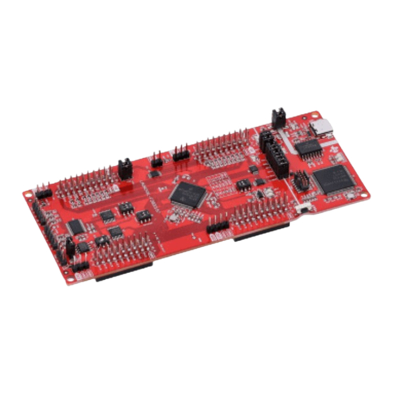
Figure 1-1
highlights the key features of the F280015x LaunchPad.
Isolated USB Interface
USB 5V Power
Isolation Header
5V & 3.3V Isolation
40-pin Boosterpack
Microcontoller
VREFHI Header
QEP Select Switch
40-pin Boosterpack
Figure 1-1. LAUNCHXL-F2800157 LaunchPad™ Board Overview
SPRUJ54A – JUNE 2023 – REVISED JULY 2023
Submit Document Feedback
ABSTRACT
(USB1, U12)
(JP1)
Headers
(JP2)
Connector Site 1
(J1 - J4)
F2800157
(U1)
(J15)
(S5)
Connector Site 2
(J5 - J8)
Encoder Interface
Copyright © 2023 Texas Instruments Incorporated
™
development kit also features two independent
CAN Interface
(J12, J13)
(J14)
C2000™ F280015x Series LaunchPad™ Development Kit
™
Real-
XDS110 Debug Probe
(U2)
XDS110 External
Debug Port
(J102)
Reset Button
(S1)
JTAG/UART
Isolation Header
(J101)
UART Select Switch
(S2)
VDD (1.2V)
Monitoring Pin
(JP4)
Boot Mode Select
Switch
(S3)
CAN Routing Switch
(S4)
CAN Termination
Resistor Jumper
(JP9)
1
Advertisement
Table of Contents

Related Manuals for Texas Instruments LaunchPad C2000 F280015 Series


Summary of Contents for Texas Instruments LaunchPad C2000 F280015 Series
-
Page 1: Figure 1-1. Launchxl-F2800157 Launchpad™ Board Overview
User's Guide C2000™ F280015x Series LaunchPad™ Development Kit ABSTRACT The LAUNCHXL-F2800157 is a low-cost development board for the Texas Instruments C2000 ™ Real- Time Microcontroller series of F280015x devices. The LAUNCHXL-F2800157 is designed around the TMS320F2800157 real-time MCU and highlights the control, analog, and communications peripherals, as well as the integrated nonvolatile memory. -
Page 2: Table Of Contents
, and Code Composer Studio ™ are trademarks of Texas Instruments. All trademarks are the property of their respective owners. C2000™ F280015x Series LaunchPad™ Development Kit SPRUJ54A – JUNE 2023 – REVISED JULY 2023 Submit Document Feedback Copyright © 2023 Texas Instruments Incorporated... -
Page 3: Board Overview
This kit is assumed to run at standard room conditions. The EVM can run at approximately Assumed Operating Conditions standard ambient temperature and pressure (SATP) with moderate-to-low humidity. SPRUJ54A – JUNE 2023 – REVISED JULY 2023 C2000™ F280015x Series LaunchPad™ Development Kit Submit Document Feedback Copyright © 2023 Texas Instruments Incorporated... -
Page 4: Using The F280015X Launchpad
Getting Started With C2000™ Real-Time Control Microcontrollers (MCUs) b. See the TI Training and Videos page c. See the C2000 Academy page C2000™ F280015x Series LaunchPad™ Development Kit SPRUJ54A – JUNE 2023 – REVISED JULY 2023 Submit Document Feedback Copyright © 2023 Texas Instruments Incorporated... -
Page 5: Boosterpacks
BoosterPacks are pluggable add-on boards for the LaunchPad ecosystem that follow a pin-out standard created by Texas Instruments. The TI and third-party ecosystem of BoosterPacks greatly expands the peripherals and potential applications that you can explore with the F280015x LaunchPad. -
Page 6: Software Development
After properly opening the serial port in your serial terminal, reset the LaunchPad by pressing the S1 reset button and observe the serial terminal to see the TI logo in ASCII art. C2000™ F280015x Series LaunchPad™ Development Kit SPRUJ54A – JUNE 2023 – REVISED JULY 2023 Submit Document Feedback Copyright © 2023 Texas Instruments Incorporated... -
Page 7: Figure 2-2. Launchpad Demo Serial Terminal - Ti Logo
0-3.3V signal to see the on-screen value change. Figure 2-3. LaunchPad Demo Serial Terminal - ADC Sampling SPRUJ54A – JUNE 2023 – REVISED JULY 2023 C2000™ F280015x Series LaunchPad™ Development Kit Submit Document Feedback Copyright © 2023 Texas Instruments Incorporated... -
Page 8: Programming And Running Other Software On The F280015X Launchpad
10. Click 'Load Program' and select the program's binary to load. The binary is loaded onto the device and can now be run and debugged. C2000™ F280015x Series LaunchPad™ Development Kit SPRUJ54A – JUNE 2023 – REVISED JULY 2023 Submit Document Feedback Copyright © 2023 Texas Instruments Incorporated... -
Page 9: Hardware Description
3.3-V 5-V Level Shifters CAN Transceiver eQEP Headers CAN Header Figure 3-1. F280015x LaunchPad™ Development Kit Block Diagram SPRUJ54A – JUNE 2023 – REVISED JULY 2023 C2000™ F280015x Series LaunchPad™ Development Kit Submit Document Feedback Copyright © 2023 Texas Instruments Incorporated... -
Page 10: Functional Description And Connections
Shunts to disconnect +5 V and/or +3.3 V between XDS110 and MCU sides Figure 3-2. LaunchPad Power Distribution Diagram C2000™ F280015x Series LaunchPad™ Development Kit SPRUJ54A – JUNE 2023 – REVISED JULY 2023 Submit Document Feedback Copyright © 2023 Texas Instruments Incorporated... -
Page 11: Figure 3-3. Launchpad Power Plane Diagram
Two blue LEDs, LED2 and LED3, are connected to the XDS110 debug probe. These indicate debugger activity and are not controllable by any application software. SPRUJ54A – JUNE 2023 – REVISED JULY 2023 C2000™ F280015x Series LaunchPad™ Development Kit Submit Document Feedback Copyright © 2023 Texas Instruments Incorporated... -
Page 12: Table 3-2. Power Led Indication Descriptions
Users can populate these components with specific values to filter out noise arriving at the device ADC input. C2000™ F280015x Series LaunchPad™ Development Kit SPRUJ54A – JUNE 2023 – REVISED JULY 2023 Submit Document Feedback Copyright © 2023 Texas Instruments Incorporated... - Page 13 1.2-V VDD rail of the TMS320F2800157PN device. This pin can not be used to supply power to an external device nor connected to an external supply. SPRUJ54A – JUNE 2023 – REVISED JULY 2023 C2000™ F280015x Series LaunchPad™ Development Kit Submit Document Feedback Copyright © 2023 Texas Instruments Incorporated...
-
Page 14: Debug Interface
XDS110 COM Port BP Headers XDS110 COM Port No Connect BP Headers BP Headers BP Headers XDS110 COM Port C2000™ F280015x Series LaunchPad™ Development Kit SPRUJ54A – JUNE 2023 – REVISED JULY 2023 Submit Document Feedback Copyright © 2023 Texas Instruments Incorporated... -
Page 15: Table 3-5. Qep Select Table - S5
PWM DAC outputs. These resistors can be removed to disconnect the signals from U18 and PWM DAC pins as needed. SPRUJ54A – JUNE 2023 – REVISED JULY 2023 C2000™ F280015x Series LaunchPad™ Development Kit Submit Document Feedback Copyright © 2023 Texas Instruments Incorporated... -
Page 16: Board Design
4.2 PCB Layout The layout source files for the LAUNCHXL-F2800157 are included in the LAUNCHXL-F2800157 design files download. C2000™ F280015x Series LaunchPad™ Development Kit SPRUJ54A – JUNE 2023 – REVISED JULY 2023 Submit Document Feedback Copyright © 2023 Texas Instruments Incorporated... -
Page 17: Figure 4-1. Top Signal - Layer 1
Board Design Figure 4-1. Top Signal - Layer 1 SPRUJ54A – JUNE 2023 – REVISED JULY 2023 C2000™ F280015x Series LaunchPad™ Development Kit Submit Document Feedback Copyright © 2023 Texas Instruments Incorporated... -
Page 18: Figure 4-2. Gnd - Layer 2
Board Design www.ti.com Figure 4-2. GND - Layer 2 C2000™ F280015x Series LaunchPad™ Development Kit SPRUJ54A – JUNE 2023 – REVISED JULY 2023 Submit Document Feedback Copyright © 2023 Texas Instruments Incorporated... -
Page 19: Figure 4-3. Pwr - Layer 3
Board Design Figure 4-3. PWR - Layer 3 SPRUJ54A – JUNE 2023 – REVISED JULY 2023 C2000™ F280015x Series LaunchPad™ Development Kit Submit Document Feedback Copyright © 2023 Texas Instruments Incorporated... -
Page 20: Figure 4-4. Bottom Signal - Layer 4
Board Design www.ti.com Figure 4-4. Bottom Signal - Layer 4 C2000™ F280015x Series LaunchPad™ Development Kit SPRUJ54A – JUNE 2023 – REVISED JULY 2023 Submit Document Feedback Copyright © 2023 Texas Instruments Incorporated... -
Page 21: Bom
F280015x LaunchPad that shows the location of selected features of the board as well as the component locations. Figure 4-5. F280015x LaunchPad Dimensions and Component Locations SPRUJ54A – JUNE 2023 – REVISED JULY 2023 C2000™ F280015x Series LaunchPad™ Development Kit Submit Document Feedback Copyright © 2023 Texas Instruments Incorporated... -
Page 22: Frequently Asked Questions
Target Scan Format as OSCAN2 format. Alternately, a working Target configuration file is included in the launchxl_ex1_f2800157_demo project "TMS320F2800157_LaunchPad.ccxml". You can use this without modifications. Figure 5-1. Target Configuration Advanced Options C2000™ F280015x Series LaunchPad™ Development Kit SPRUJ54A – JUNE 2023 – REVISED JULY 2023 Submit Document Feedback Copyright © 2023 Texas Instruments Incorporated... -
Page 23: References
• C2000WARE Quick Start Guide • C2000 SysConfig • Texas Instruments Code Composer Studio™ integrated development environment (IDE) • Texas Instruments LaunchPad Development Environment SPRUJ54A – JUNE 2023 – REVISED JULY 2023 C2000™ F280015x Series LaunchPad™ Development Kit Submit Document Feedback... -
Page 24: Other Ti Components Used In This Design
Changes from Revision * (June 2023) to Revision A (July 2023) Page • Added Section 1.3.1 ............................C2000™ F280015x Series LaunchPad™ Development Kit SPRUJ54A – JUNE 2023 – REVISED JULY 2023 Submit Document Feedback Copyright © 2023 Texas Instruments Incorporated... - Page 25 STANDARD TERMS FOR EVALUATION MODULES Delivery: TI delivers TI evaluation boards, kits, or modules, including any accompanying demonstration software, components, and/or documentation which may be provided together or separately (collectively, an “EVM” or “EVMs”) to the User (“User”) in accordance with the terms set forth herein.
- Page 26 www.ti.com Regulatory Notices: 3.1 United States 3.1.1 Notice applicable to EVMs not FCC-Approved: FCC NOTICE: This kit is designed to allow product developers to evaluate electronic components, circuitry, or software associated with the kit to determine whether to incorporate such items in a finished product and software developers to write software applications for use with the end product.
- Page 27 www.ti.com Concernant les EVMs avec antennes détachables Conformément à la réglementation d'Industrie Canada, le présent émetteur radio peut fonctionner avec une antenne d'un type et d'un gain maximal (ou inférieur) approuvé pour l'émetteur par Industrie Canada. Dans le but de réduire les risques de brouillage radioélectrique à...
- Page 28 www.ti.com EVM Use Restrictions and Warnings: 4.1 EVMS ARE NOT FOR USE IN FUNCTIONAL SAFETY AND/OR SAFETY CRITICAL EVALUATIONS, INCLUDING BUT NOT LIMITED TO EVALUATIONS OF LIFE SUPPORT APPLICATIONS. 4.2 User must read and apply the user guide and other available documentation provided by TI regarding the EVM prior to handling or using the EVM, including without limitation any warning or restriction notices.
- Page 29 Notwithstanding the foregoing, any judgment may be enforced in any United States or foreign court, and TI may seek injunctive relief in any United States or foreign court. Mailing Address: Texas Instruments, Post Office Box 655303, Dallas, Texas 75265 Copyright © 2023, Texas Instruments Incorporated...
- Page 30 TI products. TI’s provision of these resources does not expand or otherwise alter TI’s applicable warranties or warranty disclaimers for TI products. TI objects to and rejects any additional or different terms you may have proposed. IMPORTANT NOTICE Mailing Address: Texas Instruments, Post Office Box 655303, Dallas, Texas 75265 Copyright © 2023, Texas Instruments Incorporated...
Need help?
Do you have a question about the LaunchPad C2000 F280015 Series and is the answer not in the manual?
Questions and answers