Texas Instruments CC2540 User Manual
Bluetooth low energy mini development kit
Hide thumbs
Also See for CC2540:
- Software developers manual (162 pages) ,
- User manual (40 pages) ,
- Application manual (36 pages)

Related Manuals for Texas Instruments CC2540


Summary of Contents for Texas Instruments CC2540
- Page 1 Bluetooth® Low Energy CC2540 Mini Development Kit User’s Guide Document Number: SWRU270 Document Version: 1.0 Development Kit Part Number: CC2540DK-MINI...
-
Page 2: Table Of Contents
LASH ROGRAMMER OFTWARE 5.3.1 Checking the CC Debugger Firmware ................24 5.3.2 Reading or Writing a Hex File to the CC2540 ..............25 5.3.3 Reading or Writing the CC2540 Device Address.............. 26 GENERAL INFORMATION ....................... 28 ........................ 28 OCUMENT ISTORY... -
Page 3: References
SWRU270 1. References The following references provide additional information on the CC2540, the Texas Instruments Bluetooth® low energy (BLE) stack, and the BLE specification in general. (All path and file references in this document assume that the BLE development kit software has been installed to the default path C:\Texas Instruments\BLE-CC2540\) 1.1 Printed Copy Included in the Box with the Kit... -
Page 4: Introduction
Figure 1 – Hardware Included with CC2540DK-MINI 2.2 System Requirements To use the CC2540 software, a PC running Microsoft Windows (XP or later; 32-bit support only) is required, as well as Microsoft .NET Framework 3.5 Service Pack 1 (SP1) or greater. - Page 5 SWRU270 Figure 2 If you do not see it in the list, you can download the framework from Microsoft. From a hardware standpoint, the Windows PC must contain one free USB port. An additional free USB port is required in order to use the CC Debugger and the USB Dongle simultaneously. IAR Embedded Workbench for 8051 development environment is required in order to make changes to the keyfob software.
-
Page 6: Getting Started
3. Getting Started This section describes how to set up the software and get started with the CC2540 Mini Development Kit. It is assumed that the instructions found in [1] (a printed copy of the quick start guide is included with the kit) have already been completed, with both the keyfob and the dongle having been programmed with the latest hex files. -
Page 7: Determining The Com Port
SWRU270 Figure 5 Click the “Next” button. This should install the driver. It will take a few seconds for the file to load. If the installation was successful, you should see the screen to the below. Click the “Finish” button to complete the installation. - Page 8 A list of all hardware devices should appear. Under the section “Ports (COM & LPT)”, the device “TI CC2540 Low-Power RF to USB CDC Serial Port” should appear. Next to the name should be the port number (for example, COM15 in the image below): Figure 9 Take note of this port number, as it will be needed in order to use BTool.
-
Page 9: Using Btool
CC2540, can be found in [3]. 4.1 Starting the Application To start the application go into your programs by choosing Start > Programs > Texas Instruments > Bluetooth-LE > BTool. You should see the following window open up: Figure 10 In the upper left corner of the window, click the “Device”... -
Page 10: Creating Able Connection Between Usb Dongle And Keyfob
SWRU270 Figure 12 If using the USB Dongle, set the “Port” value to the COM port of the USB Dongle from step 1. For the other settings, use the default values as shown in Figure 12. Press “OK” to connect to the board. The following screen will appear: Figure 13 This screen indicates that you are now connected to the USB Dongle. -
Page 11: Scanning For Devices
SWRU270 Figure 14 4.2.2 Scanning for Devices Press the “Scan” button under the “Discover / Connect” tab: Figure 15 The USB Dongle will begin search for other BLE devices. As devices are found, the log on the left side of the screen will display the devices discovered. -
Page 12: Selecting Connection Parameters
SWRU270 Figure 16 4.2.3 Selecting Connection Parameters Before establishing a connection, you will want to set up the desired connection parameters. The default values of 100ms connection interval, 0 slave latency, and 20000ms supervision timeout should serve as a good starting point; however for different applications you may want to experiment with these values. Once the desired values have been set, be sure to click the “Set”... -
Page 13: Using The Simple Gatt Profile
SWRU270 Figure 18 If the keyfob is still in discoverable mode, a connection should be established (press the right button on the keyfob once again if the device if more than 30 seconds have passed since the device was previously made discoverable and the process has completed). -
Page 14: Reading A Characteristic Value By Uuid
SWRU270 Figure 20 4.3.1 Reading a Characteristic Value by UUID The first characteristic of the SimpleGATTProfile service has both read and write permissions, and has a UUID of 0xFFF1. The simplest way to read its value is to use the “Read Characteristic by UUID” sub- Page 14 of 28... -
Page 15: Writing A Characteristic Value
SWRU270 procedure. To do this, you will first need to click the “Read / Write” tab in BTool. Select the option “Read Using Characteristic UUID” under the “Sub-Procedure” option in the “Characteristic Read” section at the top of the screen. Enter “F1:FF” (note that the LSB is entered first, and the MSB is entered last) in the “Characteristic UUID”... -
Page 16: Reading A Characteristic Value By Handle
SWRU270 Figure 22 4.3.3 Reading a Characteristic Value by Handle After writing a new value to the first characteristic in the profile, we can read the value back to verify the write. This time, instead of reading the value by its UUID, the value will be read by its handle. Select the option “Read Characteristic Value / Descriptor”... -
Page 17: Reading Multiple Characteristic Values
SWRU270 under the “Sub-Procedure” option in the “Characteristic Read” section at the top of the screen. Enter “F2:FF” in the “Characteristic UUID” box, and click the “Read” button. A series of attribute protocol Read by Type Request packets get sent over the air from the dongle to the keyfob, and for each request an attribute protocol Read by Type Response packet gets sent back from the keyfob to the dongle. -
Page 18: Enabling Notifications
SWRU270 Figure 25 4.3.6 Enabling Notifications In BLE, it is possible for a GATT server device to “push” characteristic value data out to a client device, without being prompted with a read request. This process is called a “characteristic value notification”. Notifications are useful in that they allow a device in a BLE connection to send out as much or as little data as required at any point in time. -
Page 19: Using The Simple Keys Gatt Profile
SWRU270 Figure 26 The value should be “03” in each notification, since it is copied from the value of the third characteristic in the profile (which has a default value of 3). The third characteristic has write-only properties, and therefore can be changed. By following the procedure from section 4.3.4, the handle of the third characteristic can be found to be 0x0017. - Page 20 GATT service profile specifications have been approved by the Bluetooth SIG. Therefore the profile, including the GATT characteristic definition, the UUID values, and the functional behavior, was developed by Texas Instruments for use with the CC2540DK-MINI development kit.
-
Page 21: Programming / Debugging The Cc2540
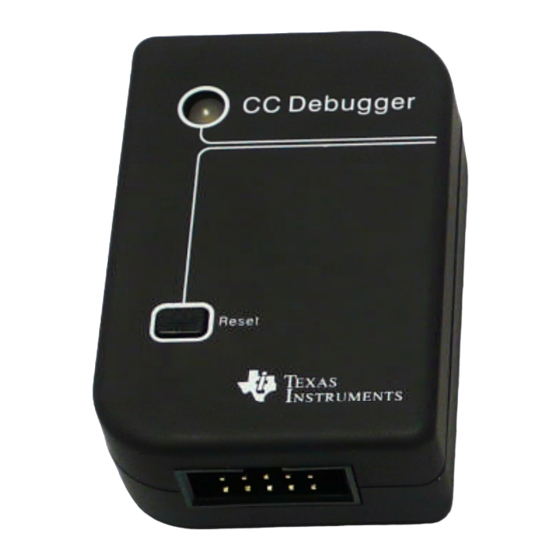
LED on the CC Debugger should turn on. If the LED is red, that means no CC2540 device was detected. If it is green, then a CC2540 device has been detected. If the keyfob is connected and the LED is red, try pressing the reset button on the CC Debugger. -
Page 22: Hardware Setup For Usb Dongle
SWRU270 Figure 31 Once the CC Debugger is set up with the status indicator LED showing green, you are ready to either read or write a hex file from the board, or to begin debugging a project using IAR. 5.2 Hardware Setup for USB Dongle The setup process for flashing the USB Dongle is very similar to the process when flashing the keyfob. - Page 23 Connect the CC Debugger to the PC USB port. The status indicator LED on the CC Debugger should turn on. If the LED is red, that means no CC2540 device was detected. If it is green, then a CC2540 device has been detected.
-
Page 24: Using Smartrf Flash Programmer Software
1.9.0.0), which is available at the following URL: http://focus.ti.com/docs/toolsw/folders/print/flash-programmer.html To start the application go into your programs by choosing Start > Programs > Texas Instruments > SmartRF Flash Programmer > SmartRF Flash Programmer. The program should open up the following... -
Page 25: Reading Or Writing A Hex File To The Cc2540
SWRU270 Figure 36 The value shown must be “0008” or higher; otherwise the debugger will not recognize the CC2540. If the firmware is “0007” or less, the firmware will need to be updated. To update the firmware, click the “…” button next to the “Flash image” text box, and select the following file: C:\Program Files\Texas Instruments\Extras\ccdebugger\cebal_fw_srf05dbg.hex... -
Page 26: Reading Or Writing The Cc2540 Device Address
SWRU270 you would like to write to the device. If you are reading from the CC2540, under “Flash image” enter the desired path and filename for the hex file. To write to the CC2540, under “Actions” select “Erase, program and verify”. To read from the CC2540, under “Actions” select “Read flash into hex-file”. To begin the read or write, click the button “Perform actions”. - Page 27 SWRU270 Figure 39 Note that every time you re-program the device using SmartRF Flash Programmer, the secondary address of the device will get set to FF:FF:FF:FF:FF:FF. This can be avoided by selecting the option “Retain IEEE address when reprogramming the chip”. A similar situation exists when a device is reprogrammed through IAR Embedded Workbench, in that the secondary address will get set to FF:FF:FF:FF:FF:FF each time.
-
Page 28: General Information
SWRU270 6. General Information 6.1 Document History Revision Date Description/Changes 2010-10-08 Initial release Page 28 of 28... - Page 29 IMPORTANT NOTICE Texas Instruments Incorporated and its subsidiaries (TI) reserve the right to make corrections, modifications, enhancements, improvements, and other changes to its products and services at any time and to discontinue any product or service without notice. Customers should obtain the latest relevant information before placing orders and should verify that such information is current and complete.
Need help?
Do you have a question about the CC2540 and is the answer not in the manual?
Questions and answers