Table of Contents
Advertisement
Quick Links
CC1125 Development Kit Quick Start Guide
Opening the Box and Running the Packet Error Rate Test
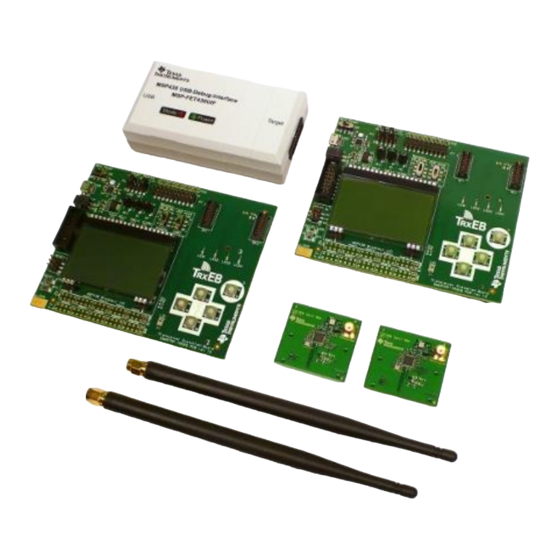
1. Kit Contents
2 x SmartRF Transceiver Evaluation Boards
(TrxEB)
2 x CC1125 ETSI Cat1 868 MHz Boards
(CC1125EM-CAT1-868)
2 x W5017 Pulse Antennas
1 x MSP430 Debug Probe (FET)
2 x Micro USB Cables
1 x Standard USB Cable
1 x 14-pin Flat Cable
4 x 1.5 Volt AA Batteries
Documentation
4. Select Board Mode
Use the switches S1 and S2 to select the
operating mode of the board. For the sake of this
quick start guide, please select "Enable" and
"UART". This configuration will make it possible
to communicate directly with the MSP430 over a
virtual COM port on the PC.
7. Welcome Screen
Turn on power with the Main Power switch. You
should now see the Texas Instruments logo and
a short description of the buttons on the LCD.
Pushing any of the five buttons on the board will
take you to the main menu.
NB! If you don't see anything on the screen
make sure the mode switches are in the
correct positions (see step 4 above).
2. TrxEB Overview
Power
EM
Board Mode
Selection
Breakout
Switches
Main
Power
Switch
USB
MSP430
MSP430
LCD
Debug
Breakout
Interface
connector
5. Power Options
There are several ways of applying power to the
TrxEB.
USB (5V)
2 x 1.5 V AA batteries
External regulated power supply
MSP430 debugger
For the batteries and USB, there are voltage
regulators on the TrxEB that will set the on-board
voltage to 3.3 V.
Warning! To minimize risk of injury or property
damage, never use rechargeable batteries to
power the board. Always select a power source
that is suitably rated for use with this EVM, not
exceeding 3.6 VDC, with a current output
rating between 0 and 500 mA.
8. Packet Error Rate Test
Select the PER (Packet Error Rate) test by
highlighting the selection using the up/down
buttons. Confirm your selection by pressing
Enter (right button).
Web sites:
www.ti.com/lprf
E2E Forum:
www.ti.com/lprf-forum
3. Plug the EM into the TrxEB
EM
Connectors
Insert a CC1125EM board into the TrxEB as
shown above. Connect the antenna to the SMA
connector on the EM.
Caution! The kit contains ESD sensitive
components.
prevent
minimize risk of injury, avoid touching
components
Buttons
LEDs
symbolized as hot.
The hardware in this kit is tested and complies with
ETSI/R&TTE over temperature from 0 to +35°C. The
W5017 whip antenna from Pulse has a gain of 2 dBi.
The CC1125 is a receiver category 1 device, c.f. ETSI
EN 300 220-1, §4.1.1.
6. Select Power Source
Depending on the power source, make sure you
connect jumpers to the appropriate pins on the
"Power Source" header. For instance, if you use
batteries, use a jumper to short-circuit pin 1 and
2 on the header. See back side of board for
explanation of the jumpers..
Note that there should only be one active
power source at any one time. Do not leave
the EVM powered when unattended.
9. Select Test Mode
The PER test can be run is several modes. Easy
Mode sets up a one-way test and uses default
settings. This test is convenient for practical
range testing.
The other test modes are described in the
"Software Examples for CC112x, CC11xL and
CC1101 User's Guide".
To proceed, highlight "Easy Mode" and press
Enter (right button).
Make sure to subscribe to the Low-Power RF
Newsletter to receive information about updates to
documentation, new product releases, and more.
Sign up on the TI web pages.
SWRU317
March 2012
Handle
with
care
to
permanent
damage.
To
during
operation
if
Advertisement
Table of Contents

Related Manuals for Texas Instruments CC1125


Summary of Contents for Texas Instruments CC1125
- Page 1 ETSI/R&TTE over temperature from 0 to +35°C. The 4 x 1.5 Volt AA Batteries W5017 whip antenna from Pulse has a gain of 2 dBi. Documentation The CC1125 is a receiver category 1 device, c.f. ETSI EN 300 220-1, §4.1.1. 4. Select Board Mode 5. Power Options 6.
- Page 2 SmartRF Studio from Select the “Sub 1 GHz” tab and double click the run link tests with another CC1125 on a www.ti.com/smartrfstudio. highlighted CC1125 device icon. SmartRF TrxEB connected to the PC.
- Page 3 EVALUATION BOARD/KIT/MODULE (EVM) ADDITIONAL TERMS Texas Instruments (TI) provides the enclosed Evaluation Board/Kit/Module (EVM) under the following conditions: The user assumes all responsibility and liability for proper and safe handling of the goods. Further, the user indemnifies TI from all claims arising from the handling or use of the goods.
- Page 4 For EVMs annotated as FCC – FEDERAL COMMUNICATIONS COMMISSION Part 15 Compliant Caution This device complies with part 15 of the FCC Rules. Operation is subject to the following two conditions: (1) This device may not cause harmful interference, and (2) this device must accept any interference received, including interference that may cause undesired operation.
- Page 5 For EVMs annotated as IC – INDUSTRY CANADA Compliant This Class A or B digital apparatus complies with Canadian ICES-003. Changes or modifications not expressly approved by the party responsible for compliance could void the user’s authority to operate the equipment. Concerning EVMs including radio transmitters This device complies with Industry Canada licence-exempt RSS standard(s).
- Page 6 Also, please do not transfer this product, unless you give the same notice above to the transferee. Please note that if you could not follow the instructions above, you will be subject to penalties of Radio Law of Japan. Texas Instruments Japan Limited (address) 24-1, Nishi-Shinjuku 6 chome, Shinjukku-ku, Tokyo, Japan http://www.tij.co.jp 【ご使用にあたっての注意】...
- Page 7 EVALUATION BOARD/KIT/MODULE (EVM) WARNINGS, RESTRICTIONS AND DISCLAIMERS For Feasibility Evaluation Only, in Laboratory/Development Environments. Unless otherwise indicated, this EVM is not a finished electrical equipment and not intended for consumer use. It is intended solely for use for preliminary feasibility evaluation in laboratory/development environments by technically qualified electronics experts who are familiar with the dangers and application risks associated with handling electrical mechanical components, systems and subsystems.
- Page 8 IMPORTANT NOTICE Texas Instruments Incorporated and its subsidiaries (TI) reserve the right to make corrections, modifications, enhancements, improvements, and other changes to its products and services at any time and to discontinue any product or service without notice. Customers should obtain the latest relevant information before placing orders and should verify that such information is current and complete.
Need help?
Do you have a question about the CC1125 and is the answer not in the manual?
Questions and answers