Texas Instruments C2000 Workshop Manual And Lab Manual
Microcontroller workshop
Hide thumbs
Also See for C2000:
- Technical training manual (88 pages) ,
- User manual (41 pages) ,
- Quick start manual (9 pages)

Subscribe to Our Youtube Channel
Related Manuals for Texas Instruments C2000


Summary of Contents for Texas Instruments C2000
- Page 1 C2000™ Microcontroller Workshop Workshop Guide and Lab Manual F28xMcuMdw Revision 5.0 May 2014 Technical Training Organization...
- Page 2 Important Notice Important Notice Texas Instruments and its subsidiaries (TI) reserve the right to make changes to their products or to discontinue any product or service without notice, and advise customers to obtain the latest version of relevant information to verify, before placing orders, that information being relied on is current and complete.
- Page 3 Copyright © 2014 Texas Instruments. All rights reserved. The objective of this workshop is to gain a fully understand and a complete working knowledge of the C2000 microcontroller. This will be accomplished through detailed presentations and hands-on lab exercises. The workshop will start with the basic topics and progress to more advanced topics in a logical flow such that each topic and lab exercise builds on the previous one presented.
-
Page 4: Table Of Contents
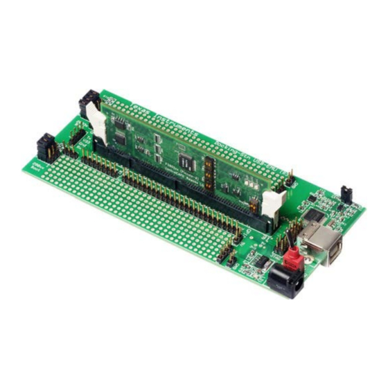
The materials required for this workshop are available using the links shown at the top of this slide. An F28069 Experimenter’s Kit and a jumper wire will be needed for the lab exercises. The C2000 Microcontroller Workshop - Introduction... - Page 5 GPIO34. We will be using this LED as a visual indicator during the lab exercises. The GPIO and ADC lines from the F28069 device are pinned out to the Docking Station headers. We will be using a jumper wire to connect various GPIO and ADC lines on these headers. C2000 Microcontroller Workshop - Introduction...
- Page 6 F2833x column; therefore, the F28069, being the most feature-rich Piccolo device, was chosen as the platform for this workshop. The knowledge learned from this device will be applicable to all C2000 product lines. C2000 Microcontroller Workshop - Introduction...
-
Page 7: Architecture Overview
This architectural overview introduces the basic architecture of the C2000™ Piccolo™ series of microcontrollers from Texas Instruments. The Piccolo™ series adds a new level of general purpose processing ability unseen in any previous DSP/MCU chips. The C2000™ is ideal for applications combining digital signal processing, microcontroller processing, efficient C code execution, and operating system tasks. - Page 8 Special Instructions..........................1-6 Pipeline Advantage ..........................1-7 F28x CPU + FPU + VCU Pipeline ......................1-8 Memory ..............................1-9 Memory Map ............................1-9 Code Security Module (CSM) ......................1-10 Peripherals ............................1-10 Fast Interrupt Response .........................1-11 Summary ..............................1-12 1 - 2 C2000 Microcontroller Workshop - Architecture Overview...
-
Page 9: Architecture Overview
The PIE block, or Peripheral Interrupt Expansion block, manages the interrupts from the peripherals. In the bottom right corner is the general-purpose I/O. Also, the CPU has a watchdog module and three 32-bit general-purpose timers available. C2000 Microcontroller Workshop - Architecture Overview 1 - 3... -
Page 10: Tms320C2000™ Internal Bussing
Harvard Bus Architecture, enables the F28x to fetch an instruction, read a data value and write a data value in a single cycle. All peripherals and memories are attached to the memory bus and will prioritize memory accesses. 1 - 4 C2000 Microcontroller Workshop - Architecture Overview... -
Page 11: F28X Cpu + Fpu + Vcu And Cla
The, F28x is source code compatible with the 24x/240x devices and previously written code can be reassembled to run on a F28x device, allowing for migration of existing code onto the F28x. C2000 Microcontroller Workshop - Architecture Overview 1 - 5... -
Page 12: Special Instructions
Atomics are small common instructions that are non-interuptable. The atomic ALU capability supports instructions and code that manages tasks and processes. These instructions usually execute several cycles faster than traditional coding. 1 - 6 C2000 Microcontroller Workshop - Architecture Overview... -
Page 13: Pipeline Advantage
This pipelining also enables the F28x to execute at high speeds without resorting to expensive high-speed memories. Special branch-look-ahead hardware minimizes the latency for conditional discontinuities. Special store conditional operations further improve performance. C2000 Microcontroller Workshop - Architecture Overview 1 - 7... -
Page 14: F28X Cpu + Fpu + Vcu Pipeline
One delay slot Everything else* Load, Store, Compare, Single cycle Min, Max, Absolute and No delay slot Negative value * Note: MOV32 between FPU and CPU registers is a special case. 1 - 8 C2000 Microcontroller Workshop - Architecture Overview... -
Page 15: Memory
Also in this space, you will find the PIE block. Memory blocks L0 through L8 are grouped together. L0 through L3 are accessible by the CPU and CLA. L5 through L8 are accessible by the DMA. C2000 Microcontroller Workshop - Architecture Overview 1 - 9... -
Page 16: Code Security Module (Csm)
F28x device you choose. • • ePWM • • eCAP • • eQEP • • Analog-to-Digital Converter McBSP • • Watchdog Timer eCAN • • • • GPIO 1 - 10 C2000 Microcontroller Workshop - Architecture Overview... -
Page 17: Fast Interrupt Response
DBSTAT PC(msw) PC(lsw) The C2000 devices feature a very fast interrupt response manager using the PIE block. This allows up to 96 possible interrupt vectors to be processed by the CPU. More details about this will be covered in the reset, interrupts, and system initialization modules. -
Page 18: Summary
128Kw on-chip flash memory Code security module (CSM) Control peripherals 12-bit ADC module Comparators Direct memory access (DMA) Up to 54 shared GPIO pins Communications peripherals 1 - 12 C2000 Microcontroller Workshop - Architecture Overview... -
Page 19: Programming Development Environment
Create a Project Set Build Options Create a user linker command file which: Describes a system’s available memory Indicates where sections will be placed in memory C2000 Microcontroller Workshop - Programming Development Environment 2 - 1... - Page 20 Creating a Linker Command File ......................2-12 Sections..............................2-12 Linker Command Files (.cmd) ......................2-15 Memory-Map Description .........................2-15 Section Placement..........................2-16 Summary: Linker Command File ......................2-17 Lab File Directory Structure........................2-18 Lab 2: Linker Command File .........................2-19 2 - 2 C2000 Microcontroller Workshop - Programming Development Environment...
-
Page 21: Programming Development Environment
The high level of modularity and portability resulting from this system simplifies the processes of verification, debug and maintenance. The process of COFF development is presented in greater detail in the following paragraphs. C2000 Microcontroller Workshop - Programming Development Environment 2 - 3... -
Page 22: Code Composer Studio
CCS is based on the Eclipse open source software framework. The Eclipse software framework was originally developed as an open framework for creating development tools. Eclipse offers an excellent software framework for building software development environments and it is 2 - 4 C2000 Microcontroller Workshop - Programming Development Environment... -
Page 23: Edit And Debug Perspective (Ccsv6)
Code Composer Studio has “Edit” and “Debug” perspectives. Each perspective provides a set of functionality aimed at accomplishing a specific task. In the edit perspective, views used during code development are displayed. In the debug perspective, views used during debug are displayed. C2000 Microcontroller Workshop - Programming Development Environment 2 - 5... -
Page 24: Target Configuration
GEL files and device configuration files. The configuration files are XML files and have a *.ccxlm file extension. Creating a Target Configuration File Target Configuration File Select connection type Select device Save configuration 2 - 6 C2000 Microcontroller Workshop - Programming Development Environment... -
Page 25: Ccsv6 Project
Either of these menus allows you to modify a project, such as add files to a project, or open the properties of a project to set the build options. C2000 Microcontroller Workshop - Programming Development Environment 2 - 7... -
Page 26: Creating A New Ccsv6 Project
1. Project Name, Location, and Device File CCS Project 2. Advanced Settings 3. Project Templates and Examples After a project is created, the build options are configured. 2 - 8 C2000 Microcontroller Workshop - Programming Development Environment... -
Page 27: Ccsv6 Build Options - Compiler / Linker
(configurations) in each new project you create. The Release (optimized) configuration invokes the optimizer with –o3 and disables source-level, symbolic debugging by omitting –g (which disables some optimizations to enable debug). C2000 Microcontroller Workshop - Programming Development Environment 2 - 9... -
Page 28: Ccsv6 Debug Environment
Target Menu launching options. Connect Connect to hardware targets. TI Debug Toolbar Target Target Menu Debug View Context Menu Terminate All Terminates all active debug sessions. Target Menu Debug View Toolbar 2 - 10 C2000 Microcontroller Workshop - Programming Development Environment... - Page 29 Step Over tion. If the instruction is an assembly subroutine, TI Explicit Stepping Toolbar the debugger executes the assembly subroutine Target Advanced Menu and then halts after the assembly function returns. C2000 Microcontroller Workshop - Programming Development Environment 2 - 11...
-
Page 30: Creating A Linker Command File
RAM. The preceding diagram illustrated four sections: • Global Variables • Initial Values for global variables • Local Variables (i.e. the stack) • Code (the actual instructions) 2 - 12 C2000 Microcontroller Workshop - Programming Development Environment... - Page 31 Variables (.ebss – uninitialized data) Uninitialized data memory locations can be changed and manipulated by the program code during runtime execution. Unlike program code or constants, uninitialized data or variables must reside C2000 Microcontroller Workshop - Programming Development Environment 2 - 13...
- Page 32 1. Defining the various regions of memory (on-chip SARAM vs. FLASH vs. External Memory). 2. Describing what sections go into which memory regions 3. Running the linker with “build” or “rebuild” 2 - 14 C2000 Microcontroller Workshop - Programming Development Environment...
-
Page 33: Linker Command Files (.Cmd)
For example, if you placed a 64Kw FLASH starting at memory location 0x3E8000, it would read: MEMORY FLASH: origin = 0x3E8000 , length = 0x010000 Each memory segment is defined using the above format. If you added M0SARAM and M1SARAM, it would look like: C2000 Microcontroller Workshop - Programming Development Environment 2 - 15... -
Page 34: Section Placement
The SECTIONS section will specify how you want the sections to be distributed through memory. The following code is used to link the sections into the memory specified in the previous example: 2 - 16 C2000 Microcontroller Workshop - Programming Development Environment... -
Page 35: Summary: Linker Command File
Memory Map Description Name Location Size Sections Description Directs software sections into named memory regions Allows per-file discrimination Allows separate load/run locations C2000 Microcontroller Workshop - Programming Development Environment 2 - 17... -
Page 36: Lab File Directory Structure
Original source files are always available for reuse, if a file becomes corrupted Note: CCSv6 will automatically add ALL files contained in the folder where the project is created 2 - 18 C2000 Microcontroller Workshop - Programming Development Environment... -
Page 37: Lab 2: Linker Command File
Windows Start menu. When CCS loads, a dialog box will prompt you for the location of a workspace folder. Use the default location for the workspace and click OK. C2000 Microcontroller Workshop - Programming Development Environment 2 - 19... - Page 38 4. In the next window that appears, select the emulator using the “Connection” pull-down list and choose “Texas Instruments XDS100v1 USB Emulator”. In the “Board or Device” box type F28069 to filter the options. In the box below, check the box to select “Experimenter’s Kit –...
- Page 39 14. A “Properties” window will open and in the section on the left under “Build” be sure that the “C2000 Compiler” and “C2000 Linker” options are visible. Next, under “C2000 Linker” select the “Basic Options”. Notice that .out and .map files are being specified.
- Page 40 Lab 2: Linker Command File 15. Under “C2000 Compiler” select the “Processor Options”. Notice the “Use large memory model” and “Unified memory” boxes are checked. Next, notice the “Specify CLA support” is set to cla0, the “Specify floating point support” is set to fpu32, and the “Specify VCU support”...
- Page 41 27. The Terminate button will terminate the active debug session, close the debugger and return CCS to the “CCS Edit Perspective” view. Click: Run Terminate or use the Terminate icon: C2000 Microcontroller Workshop - Programming Development Environment 2 - 23...
- Page 42 Lab 2: Linker Command File 28. Next, close the project by right-clicking on Lab2 in the Project Explorer window and select Close Project. End of Exercise 2 - 24 C2000 Microcontroller Workshop - Programming Development Environment...
-
Page 43: Peripheral Register Header Files
Understand the usage of the F2806x C-Code Header Files Be able to program peripheral registers Understand how the structures are mapped with the linker command file C2000 Microcontroller Workshop - Peripheral Registers Header Files 3 - 1... - Page 44 F2806x C-Code Header Files ........................3-9 Peripheral Structure .h File ........................3-9 Global Variable Definitions File .......................3-11 Mapping Structures to Memory ......................3-12 Linker Command File ........................3-12 Peripheral Specific Routines......................3-13 Summary ..............................3-14 3 - 2 C2000 Microcontroller Workshop - Peripheral Registers Header Files...
-
Page 45: Traditional And Structure Approach To C Coding
Disadvantages? Requires individual masks to be generated to manipulate individual bits, it cannot easily display bit fields in the debugger window, and it will generate less efficient code in many cases. C2000 Microcontroller Workshop - Peripheral Registers Header Files 3 - 3... - Page 46 Disadvantages? Can be difficult to remember the structure names and more to type; however, the edit auto complete feature of Code Composer Studio will eliminate these disadvantages. 3 - 4 C2000 Microcontroller Workshop - Peripheral Registers Header Files...
- Page 47 Expressions Window using Structures With the structure approach, we can add the peripheral to an expressions window, allowing us to C2000 Microcontroller Workshop - Peripheral Registers Header Files 3 - 5...
- Page 48 - Hard to read the code w/o comments 9 words, 9 cycles - User had to determine the bit mask * C28x Compiler v5.0.1 with -g and either -o1, -o2, or -o3 optimization level 3 - 6 C2000 Microcontroller Workshop - Peripheral Registers Header Files...
-
Page 49: Naming Conventions
The most common naming conventions used are PeripheralName.RegisterName.all, which will access the full 16 or 32-bit register; and PeripheralName.RegisterName.bit.FieldName, which will access the specified bit fields of a register. C2000 Microcontroller Workshop - Peripheral Registers Header Files 3 - 7... - Page 50 “all” or “bit”. In this example “bit” is selected. Then, when you type the “.” a window opens up, allowing you to select a bit field. In this example RESET is selected. And now, the structure is completed. 3 - 8 C2000 Microcontroller Workshop - Peripheral Registers Header Files...
-
Page 51: F2806X C-Code Header Files
.h header file can be included individually in an application that does not use all the header files, or you can comment out the ones you do not need. (Also includes typedef statements). C2000 Microcontroller Workshop - Peripheral Registers Header Files 3 - 9... - Page 52 The header file package contains a .h file for each peripheral in the device. The F2806x_Device.h file is the main include file. It will include all of the other .h files. There are 3 - 10 C2000 Microcontroller Workshop - Peripheral Registers Header Files...
-
Page 53: Global Variable Definitions File
Each structure is placed in its own section using a DATA_SECTION pragma to allow linking to the correct memory. The second step for using the header files is to add F2806x_GlobalVariableDefs.c file to your project. C2000 Microcontroller Workshop - Peripheral Registers Header Files 3 - 11... -
Page 54: Mapping Structures To Memory
The user can modify their own linker command file, or use a pre-configured linker command file such as F28069.cmd. This file has the peripheral memory regions defined and tied to the individual peripheral. 3 - 12 C2000 Microcontroller Workshop - Peripheral Registers Header Files... -
Page 55: Peripheral Specific Routines
Example projects for each peripheral Helpful to get you started The peripheral register header file package includes example projects for each peripheral. This can be very helpful to getting you started. C2000 Microcontroller Workshop - Peripheral Registers Header Files 3 - 13... -
Page 56: Summary
Code Composer Studio, and TI has already done the work for you. Just make sure to use the correct header file package for your device. 3 - 14 C2000 Microcontroller Workshop - Peripheral Registers Header Files... -
Page 57: Reset And Interrupts
This module describes the interrupt process and explains how the Peripheral Interrupt Expansion (PIE) works. Module Objectives Module Objectives Describe the F28x reset process List the event sequence during an interrupt Describe the F28x interrupt structure C2000 Microcontroller Workshop - Reset and Interrupts 4 - 1... - Page 58 Interrupt Enable Register (IER) ......................4-11 Interrupt Global Mask Bit (INTM) ....................4-12 Peripheral Interrupt Expansion (PIE) ....................4-12 PIE Block Initialization ........................4-14 Interrupt Signal Flow – Summary .....................4-16 Interrupt Response and Latency ......................4-17 4 - 2 C2000 Microcontroller Workshop - Reset and Interrupts...
-
Page 59: Reset
Additionally, the device incorporates an on-chip voltage regulator to generate the core voltage. C2000 Microcontroller Workshop - Reset and Interrupts 4 - 3... -
Page 60: Reset - Bootloader
The boot is then determined by two GPIO pins and two OTP locations named OTP_KEY and OTP_BMODE, which are located in the OTP. 4 - 4 C2000 Microcontroller Workshop - Reset and Interrupts... -
Page 61: Emulation Boot Mode
The boot modes are parallel I/O, SCI, SPI, I2C, OTP, CAN, M0SARAM, FLASH, and Wait. In addition, there is a GetMode, which emulates the stand-alone boot mode. C2000 Microcontroller Workshop - Reset and Interrupts 4 - 5... -
Page 62: Stand-Alone Boot Mode
In summary, the reset code flow is as follows: The reset vector is fetched from the boot ROM. Then, the execution entry is determined by emulation boot mode or stand-alone boot mode. The boot mode options are M0SARAM, OTP, FLASH, and boot loading routines. 4 - 6 C2000 Microcontroller Workshop - Reset and Interrupts... -
Page 63: Emulation Boot Mode Using Code Composer Studio Gel
*0xD00 = 0x55AA; /* EMU_KEY = 0x 55AA */ *0xD01 = 0x000B; /* Boot to FLASH To access the GEL file use: Tools Debugger Options Generic Debugger Options C2000 Microcontroller Workshop - Reset and Interrupts 4 - 7... -
Page 64: Getting To Main()
After reset how do we get to main? When the bootloader process is completed, a branch to the compiler runtime support library is located at the code entry point. This branch to _c_int00 is executed, then the compiler environment is set up, and finally main is called. 4 - 8 C2000 Microcontroller Workshop - Reset and Interrupts... -
Page 65: Interrupts
Interrupt Expansion block, is connected to the core interrupt lines 1 through 12. This block manages and expands the 12 core interrupt lines, allowing up to 96 possible interrupt sources. C2000 Microcontroller Workshop - Reset and Interrupts 4 - 9... -
Page 66: Interrupt Processing
Notice that the interrupt global mask bit is zero when enabled and one when disabled. The interrupt enable register is managed by ORing and ANDing mask values. The interrupt global mask bit is managed using inline assembly. 4 - 10 C2000 Microcontroller Workshop - Reset and Interrupts... -
Page 67: Interrupt Flag Register (Ifr)
IER; IER |= 0x0008; //enable INT4 in IER IER &= 0xFFF7; //disable INT4 in IER Compiler generates atomic instructions (non-interruptible) for setting/clearing IER Register cleared on reset C2000 Microcontroller Workshop - Reset and Interrupts 4 - 11... -
Page 68: Interrupt Global Mask Bit (Intm)
12 Interrupts Core INT11.y interrupt group INT12.y interrupt group (TINT1) INT13 (TINT2) INT14 We have already discussed the interrupt process in the core. Now we need to look at the 4 - 12 C2000 Microcontroller Workshop - Reset and Interrupts... - Page 69 PIE interrupt acknowledge register, and a PIE control register. The enable PIE bit in the PIE control register must be set during initialization for the PIE block to be enabled. C2000 Microcontroller Workshop - Reset and Interrupts 4 - 13...
-
Page 70: Pie Block Initialization
The interrupt vector table, as mapped in the PIE interrupt assignment table, is located in the PieVect.c file. During initialization in main, we have a function call to PieCtrl.c. In this file, a 4 - 14 C2000 Microcontroller Workshop - Reset and Interrupts... - Page 71 PIE block. When an interrupt occurs, the PIE block contains a vector to the interrupt service routine located in DefaultIsr.c. C2000 Microcontroller Workshop - Reset and Interrupts 4 - 15...
-
Page 72: Interrupt Signal Flow - Summary
Next, if the core interrupt enable register and global interrupt mask is enabled, the PIE vector table will redirect the code to the interrupt service routine. 4 - 16 C2000 Microcontroller Workshop - Reset and Interrupts... -
Page 73: Interrupt Response And Latency
Minimum latency (to when real work occurs in the ISR): Internal interrupts: 14 cycles External interrupts: 16 cycles Maximum latency: Depends on wait states, INTM, etc. C2000 Microcontroller Workshop - Reset and Interrupts 4 - 17... - Page 74 Interrupts 4 - 18 C2000 Microcontroller Workshop - Reset and Interrupts...
-
Page 75: System Initialization
EALLOW protected registers will be covered. Module Objectives Module Objectives OSC/PLL Clock Module Watchdog Timer General Purpose Digital I/O External Interrupts Low Power Modes Register Protection C2000 Microcontroller Workshop - System Initialization 5 - 1... - Page 76 System Initialization ...........................5-1 Module Topics ............................5-2 Oscillator/PLL Clock Module ........................5-3 Watchdog Timer ............................5-7 General-Purpose Digital I/O .........................5-12 External Interrupts ..........................5-16 Low Power Modes..........................5-17 Register Protection ..........................5-19 Lab 5: System Initialization ........................5-21 5 - 2 C2000 Microcontroller Workshop - System Initialization...
- Page 77 The on-chip oscillator and phase-locked loop (PLL) block provide all the necessary clocking signals for the F2806x devices. The two internal oscillators (INTOSC1 and INTOSC2) need no external components. C2000 Microcontroller Workshop - System Initialization 5 - 3...
- Page 78 Other peripherals are clocked by SYSCLKOUT and use their own clock prescalers for operation. 5 - 4 C2000 Microcontroller Workshop - System Initialization...
-
Page 79: Oscillator/Pll Clock Module
001 = /2 01 = external 1 = internal OSC2 010 = /4 10 = internal OSC1 011 = /8 11 = internal OSC2 100 = /16 1xx = reserved 0 = default C2000 Microcontroller Workshop - System Initialization 5 - 5... - Page 80 The peripheral clock control register allows individual peripheral clock signals to be enabled or disabled. If a peripheral is not being used, its clock signal could be disabled, thus reducing power consumption. 5 - 6 C2000 Microcontroller Workshop - System Initialization...
-
Page 81: Watchdog Timer
Indeed, this is plenty of time to get the watchdog configured as desired and serviced. A failure of your software to properly handle the watchdog after reset could cause an endless cycle of watchdog initiated resets to occur. C2000 Microcontroller Workshop - System Initialization 5 - 7... - Page 82 During run time, the correct keys must be written into the watchdog key register before the watchdog counter overflows and issues a reset or interrupt. Issuing a reset or interrupt is user-selectable. 5 - 8 C2000 Microcontroller Workshop - System Initialization...
- Page 83 1 0 0 OSCCLK / 512 / 8 1 0 1 OSCCLK / 512 / 16 1 1 0 OSCCLK / 512 / 32 1 1 1 OSCCLK / 512 / 64 C2000 Microcontroller Workshop - System Initialization 5 - 9...
- Page 84 WD counter enabled for reset on next AAh write No effect; WD counter not reset on next AAh write No action due to previous invalid value WD counter enabled for reset on next AAh write WD counter is reset 5 - 10 C2000 Microcontroller Workshop - System Initialization...
- Page 85 WDENINT WDOVERRIDE WD Interrupt Status WD Enable Interrupt (read only) 0 = WD generates a MCU reset 0 = active 1 = WD generates a WDINT interrupt 1 = not active C2000 Microcontroller Workshop - System Initialization 5 - 11...
-
Page 86: General-Purpose Digital I/O
Qualification • (GPIO 0-44) GPxPUD GPxQSEL1 GPxQSEL2 Internal Pull-Up GPxCTRL 0 = enable (default GPIO 12-58) 1 = disable (default GPIO 0-11) * See device datasheet for pin function selection matrices 5 - 12 C2000 Microcontroller Workshop - System Initialization... - Page 87 The GPIO input qualification feature allows filtering out noise on a pin. The user would select the number of samples and qualification period. Qualification is available on ports A and B only and is individually selectable per pin. C2000 Microcontroller Workshop - System Initialization 5 - 13...
- Page 88 GPIO B Direction Register [GPIO 32 – 63] GPBPUD GPIO B Pull-Up Disable Register [GPIO 32 – 63] AIOMUX1 ANALOG I/O Mux1 Register [AIO 0 – 15] AIODIR ANALOG I/O Direction Register [AIO 0 – 15] 5 - 14 C2000 Microcontroller Workshop - System Initialization...
- Page 89 ANALOG I/O Data Register [AIO 0 – 15] AIOSET ANALOG I/O Data Set Register [AIO 0 – 15] AIOCLEAR ANALOG I/O Data Clear Register [AIO 0 – 15] AIOTOGGLE ANALOG I/O Data Toggle [AIO 0 – 15] C2000 Microcontroller Workshop - System Initialization 5 - 15...
-
Page 90: External Interrupts
Pin Selection Register chooses which pin the signal comes out on Only one pin can be assigned to each interrupt signal Configuration Register controls the enable/disable and polarity Counter Register holds the interrupt counter 5 - 16 C2000 Microcontroller Workshop - System Initialization... -
Page 91: Low Power Modes
LP mode * QUALSTDBY will qualify the GPIO wakeup signal in series with the GPIO port qualification. This is useful when GPIO port qualification is not available or insufficient for wake-up purposes. C2000 Microcontroller Workshop - System Initialization 5 - 17... - Page 92 GPIO13 GPIO12 GPIO11 GPIO10 GPIO9 GPIO8 GPIO7 GPIO6 GPIO5 GPIO4 GPIO3 GPIO2 GPIO1 GPIO0 Wake device from HALT and STANDBY mode (GPIO Port A) 0 = disable (default) 1 = enable 5 - 18 C2000 Microcontroller Workshop - System Initialization...
-
Page 93: Register Protection
EALLOW bit controlled by assembly level instructions ‘EALLOW’ sets the bit (register access enabled) ‘EDIS’ clears the bit (register access disabled) EALLOW bit cleared upon ISR entry, restored upon exit C2000 Microcontroller Workshop - System Initialization 5 - 19... - Page 94 See device datasheet and peripheral users guides for detailed listings EALLOW register access C-code example: asm(" EALLOW"); // enable protected register access SysCtrlRegs.WDKEY=0x55; // write to the register asm(" EDIS"); // disable protected register access 5 - 20 C2000 Microcontroller Workshop - System Initialization...
-
Page 95: Lab 5: System Initialization
2. Right-click on Lab5 in the Project Explorer window and add (copy) the following files to the project (Add Files…) from C:\C28x\Labs\Lab5\Files: CodeStartBranch.asm Lab.h DelayUs.asm Lab_5_6_7.cmd F2806x_DefaultIsr.h Main_5.c F2806x_GlobalVariableDefs.c SysCtrl.c F2806x_Headers_nonBIOS.cmd Watchdog.c Gpio.c C2000 Microcontroller Workshop - System Initialization 5 - 21... - Page 96 3. Setup the build options by right-clicking on Lab5 in the Project Explorer window and select Properties. We need to setup the include search path to include the peripheral register header files. Under “C2000 Compiler” select “Include Options”. In the lower box that opens (“Add dir to #include search path”) click the Add icon (first icon with green plus sign).
- Page 97 17. Run your code. Where did your code stop? Are the results as expected? If things went as expected, your code should have stopped at the breakpoint. What happened is as C2000 Microcontroller Workshop - System Initialization 5 - 23...
- Page 98 ISR. We will run the lab exercise as before, except this time the watchdog will generate an interrupt. If the registers have been configured properly, the code will be trapped in the ISR. 5 - 24 C2000 Microcontroller Workshop - System Initialization...
- Page 99 C code projects (ask your instructor if this has not already been explained). During this lab exercise, the watchdog was actually re-enabled (or disabled again) in the file Watchdog.c. C2000 Microcontroller Workshop - System Initialization 5 - 25...
- Page 100 Lab 5: System Initialization 5 - 26 C2000 Microcontroller Workshop - System Initialization...
-
Page 101: Analog-To-Digital Converter
CPU timer interrupt event, or a generated ADCINT1/2 interrupt. Module Objectives Module Objectives Understand the operation of the Analog-to-Digital converter (ADC) and Comparator Use the ADC to perform data acquisition C2000 Microcontroller Workshop - Analog-to-Digital Converter 6 - 1... - Page 102 ADC Clock and Timing ........................6-8 ADC Converter Registers ........................6-9 Signed Input Voltages ........................6-14 ADC Calibration and Reference ......................6-15 Comparator ............................6-17 Comparator Block Diagram .......................6-17 Comparator Registers ........................6-18 Lab 6: Analog-to-Digital Converter ......................6-19 6 - 2 C2000 Microcontroller Workshop - Analog-to-Digital Converter...
-
Page 103: Analog-To-Digital Converter
A multiplexer will be the same channel on the B multiplexer. The ADC interrupt logic can generate up to nine interrupts. The results for SOC 0 through 15 will appear in result registers 0 through 15. C2000 Microcontroller Workshop - Analog-to-Digital Converter 6 - 3... -
Page 104: Adc Triggering
Sample Result5 ADCINT2 12 cycles The top example on this slide shows channels A2, B3, and A7 being converted with a trigger from EPWM1SOCB. After A7 is converted, ADCINT1 is generated. 6 - 4 C2000 Microcontroller Workshop - Analog-to-Digital Converter... - Page 105 After channel A/B three is converted, ADCINT1 is generated. After channel A/B seven is converted, ADCINT2 is generated and fed back to start the process again. ADCINT1 and ADCINT2 are being used as ping-pong interrupts. C2000 Microcontroller Workshop - Analog-to-Digital Converter 6 - 5...
-
Page 106: Adc Conversion Priority
SOC4 SOCPRIORITY SOC5 SOC6 AdcRegs.SOCPRICTL SOC7 RRPOINTER SOC8 SOC9 Round Robin Pointer SOC10 Points to the last converted SOC11 round robin SOCx and SOC12 determines order SOC13 of conversions SOC14 SOC15 6 - 6 C2000 Microcontroller Workshop - Analog-to-Digital Converter... - Page 107 SOC8 is now highest RR priority RRPOINTER SOC2 & SOC12 triggers received simultaneously SOC2 is converted; RRPOINTER stays pointing to SOC7 SOC12 is converted; RRPOINTER points to SOC12; SOC13 is now highest RR priority C2000 Microcontroller Workshop - Analog-to-Digital Converter 6 - 7...
-
Page 108: Adc Clock And Timing
Interrupt Start Sampling Next Channel Max Continuous Sampling: 45 MHz = 3.46 MSPS 13 cycles / 1 sample Note: Sampling window of 7 cycles is minimum and it can be larger 6 - 8 C2000 Microcontroller Workshop - Analog-to-Digital Converter... -
Page 109: Adc Converter Registers
SOC Priority Control Register ADCREFTRIM Reference Trim Register ADCOFFTRIM Offset Trim Register ADCREV Revision Register – reserved ADCRESULTx ADC Result 0 to 15 Registers Note: ADCRESULTx header file coding is AdcResult.ADCRESULTx (not in AdcRegs) C2000 Microcontroller Workshop - Analog-to-Digital Converter 6 - 9... - Page 110 0 = not connected 1 = connected (B5) 0 = bandgap circuitry 0 = beginning of powered down conversion 1 = bandgap circuitry 1 = one cycle prior powered up to result 6 - 10 C2000 Microcontroller Workshop - Analog-to-Digital Converter...
- Page 111 Bh = ADCINB3 0Fh = ePWM6SOCA Ch = ADCINB4 10h = ePWM6SOCB Dh = ADCINB5 11h = ePWM7SOCA Eh = ADCINB6 12h = ePWM7SOCB Fh = ADCINB7 13h = ePWM8SOCA 14h = ePWM8SOCB C2000 Microcontroller Workshop - Analog-to-Digital Converter 6 - 11...
- Page 112 SIMULEN14 SIMULEN12 SIMULEN10 SIMULEN8 SIMULEN6 SIMULEN4 SIMULEN2 SIMULEN0 Simultaneous Sampling Enable Couples SOCx and SOCx+1 in simultaneous sampling mode 0 = single sample mode for SOCx and SOCx+1 1 = simultaneous sample mode for SOCx and SOCx+1 6 - 12 C2000 Microcontroller Workshop - Analog-to-Digital Converter...
- Page 113 0Ch = EOC12 is trigger for ADCINTx/y 0Dh = EOC13 is trigger for ADCINTx/y 0Eh = EOC14 is trigger for ADCINTx/y 0Fh = EOC15 is trigger for ADCINTx/y 1xh = invalid value C2000 Microcontroller Workshop - Analog-to-Digital Converter 6 - 13...
-
Page 114: Signed Input Voltages
1) Add 1.65 volts to the ADCINx 1.65V analog input ADCLO 2) Subtract “1.65” from the digital result #include “F2806x_Device.h” #define offset 0x07FF void main(void) int16 value; // signed value = AdcResult.ADCRESULT0 – offset; 6 - 14 C2000 Microcontroller Workshop - Analog-to-Digital Converter... -
Page 115: Adc Calibration And Reference
To minimize mux-to-mux variation effects, put your most critical signals on a single mux and use that mux for calibration inputs * +/-15 LSB offset, +/-30 LSB gain. See device datasheet for exact specifications C2000 Microcontroller Workshop - Analog-to-Digital Converter 6 - 15... - Page 116 2 - 0 reserved ADCREFSEL ADC Reference Selection 0 = internal (default) 1 = external VREFHI/VREFLO pins used for reference generation * See device datasheet for exact specifications and ADC reference hardware connections 6 - 16 C2000 Microcontroller Workshop - Analog-to-Digital Converter...
-
Page 117: Comparator
10-bit digital-to-analog converter. The output of the comparator is fed into the ePWM digital compare sub-module. C2000 Microcontroller Workshop - Analog-to-Digital Converter 6 - 17... -
Page 118: Comparator Registers
DACVAL Scales output of DAC from 0 – 1023 Value = 0 – 3FFh AdcRegs.COMPSTS – Compare Output Status Register 15 - 1 reserved COMPSTS Logical latched value of the comparator 6 - 18 C2000 Microcontroller Workshop - Analog-to-Digital Converter... -
Page 119: Lab 6: Analog-To-Digital Converter
CTR = PRD SOC method 2b above). The ADC end-of-conversion interrupt will be used to prompt the CPU to copy the results of the ADC conversion into a results buffer in memory. C2000 Microcontroller Workshop - Analog-to-Digital Converter 6 - 19... - Page 120 Data is continuously stored in a circular buffer • GPIO18 pin is also toggled in the ADC ISR • ADC ISR will also toggle the controlCARD LED LD3 as a visual indication that it is running 6 - 20 C2000 Microcontroller Workshop - Analog-to-Digital Converter...
-
Page 121: Control Peripherals
Save your work and close the modified files. Build and Load 7. Click the “Build” button and watch the tools run in the Console window. Check for errors in the Problems window. C2000 Microcontroller Workshop - Analog-to-Digital Converter 6 - 21... - Page 122 Click: Tools Graph Single Time and set the following values: Acquisition Buffer Size DSP Data Type 16-bit unsigned integer Sampling Rate (Hz) 50000 Start Address AdcBuf Display Data Size µs Time Display Unit Select OK to save the graph options. 6 - 22 C2000 Microcontroller Workshop - Analog-to-Digital Converter...
- Page 123 (+) to the left of “Code Composer Studio” and select “Debug”. In the section on the right notice the default setting: • “Continuous refresh interval (milliseconds)” = 500 Click OK. C2000 Microcontroller Workshop - Analog-to-Digital Converter 6 - 23...
- Page 124 Highlight DEBUG_TOGGLE with the mouse, right click and select “Add Watch Expression…” and then select OK. The global variable DEBUG_TOGGLE should now be in the “Expressions” window with a value of “1”. • Enable the “Expressions” window for continuous refresh 6 - 24 C2000 Microcontroller Workshop - Analog-to-Digital Converter...
- Page 125 (If you do not have time to work on this optional exercise, you may want to try this after the class). End of Exercise C2000 Microcontroller Workshop - Analog-to-Digital Converter 6 - 25...
- Page 126 Lab 6: Analog-to-Digital Converter 6 - 26 C2000 Microcontroller Workshop - Analog-to-Digital Converter...
- Page 127 Explain the function of Quadrature Encoder Pulse Module (eQEP) Note: Different numbers of ePWM, eCAP, and eQEP modules are available on F2806x devices. See the device datasheet for more information. C2000 Microcontroller Workshop - Control Peripherals 7 - 1...
- Page 128 Dead-Band Sub-Module ......................7-21 ePWM Chopper Sub-Module ......................7-24 ePWM Digital Compare and Trip-Zone Sub-Modules ..............7-27 ePWM Event-Trigger Sub-Module ....................7-33 Hi-Resolution PWM (HRPWM) .......................7-36 eCAP ..............................7-37 eQEP ..............................7-43 Lab 7: Control Peripherals ........................7-45 7 - 2 C2000 Microcontroller Workshop - Control Peripherals...
-
Page 129: Pwm Review
PWM signals applied to the power converter. Although energy is input to the motor in discrete packets, the mechanical inertia of the rotor acts as a smoothing filter. Dynamic motor motion is therefore similar to having applied the sinusoidal currents directly. C2000 Microcontroller Workshop - Control Peripherals 7 - 3... - Page 130 Power-switching devices are difficult to control in the proportional region but are easy to control in the saturation and cutoff region. Since PWM is a digital signal and easy for microcontrollers to generate, it is ideal for use with power-switching devices. 7 - 4 C2000 Microcontroller Workshop - Control Peripherals...
-
Page 131: Epwm
The outputs of the comparators are used as inputs to the digital compare sub-module. Next, we will look at the internal details of the ePWM module. C2000 Microcontroller Workshop - Control Peripherals 7 - 5... - Page 132 Digital TZ1-TZ3 Compare COMPxOUT The ePWM, or enhanced PWM block diagram, consists of a series of sub-modules. In this section, we will learn about the operation and details of each sub-module. 7 - 6 C2000 Microcontroller Workshop - Control Peripherals...
-
Page 133: Epwm Time-Base Sub-Module
A period register is used to control the maximum count value. Additionally, the time-base counter has the capability to be synchronized and phase-shifted with other ePWM units. C2000 Microcontroller Workshop - Control Peripherals 7 - 7... - Page 134 These modes are used to generate asymmetrical waveforms. The lower figure shows the time- base counter in the count up and down mode. This mode is used to generate symmetrical waveforms. 7 - 8 C2000 Microcontroller Workshop - Control Peripherals...
- Page 135 (lab file: EPwm.c) Name Description Structure TBCTL Time-Base Control EPwmxRegs.TBCTL.all = TBSTS Time-Base Status EPwmxRegs.TBSTS.all = TBPHS Time-Base Phase EPwmxRegs.TBPHS = TBCTR Time-Base Counter EPwmxRegs.TBCTR = TBPRD Time-Base Period EPwmxRegs.TBPRD = C2000 Microcontroller Workshop - Control Peripherals 7 - 9...
- Page 136 0 = disable 00 = EPWMxSYNCI 1 = load immediately 1 = CTR = TBPHS on 01 = CTR = 0 EPWMxSYNCI signal 10 = CTR = CMPB 11 = disable SyncOut 7 - 10 C2000 Microcontroller Workshop - Control Peripherals...
-
Page 137: Epwm Compare Sub-Module
CMPB Count Up Mode TBCTR . . . TBPRD CMPA Asymmetrical Waveform CMPB Count Down Mode TBCTR ..TBPRD CMPA Symmetrical CMPB Waveform Count Up and Down Mode C2000 Microcontroller Workshop - Control Peripherals 7 - 11... - Page 138 01 = load on CTR = PRD 1 = immediate mode; 10 = load on CTR = 0 or PRD shadow register not used 11 = freeze (no load possible) 7 - 12 C2000 Microcontroller Workshop - Control Peripherals...
-
Page 139: Epwm Action Qualifier Sub-Module
EPWMA and EPWMB EPWM Time-Base Counter equals: Output Force Actions Zero CMPA CMPB TBPRD Do Nothing Clear Low ↓ ↓ ↓ ↓ ↓ Set High ↑ ↑ ↑ ↑ ↑ Toggle C2000 Microcontroller Workshop - Control Peripherals 7 - 13... - Page 140 Here, on the EPWMA output, the waveform will be set high on zero match and clear low on compare A match. On the EPWMB output, the waveform will be set high on zero match and clear low on compare B match. 7 - 14 C2000 Microcontroller Workshop - Control Peripherals...
- Page 141 Here you can see that we can have different output actions on the up-count and down-count using a single compare register. So, for the EPWMA and EPWMB outputs, we are setting high on the C2000 Microcontroller Workshop - Control Peripherals 7 - 15...
- Page 142 EPWMA output set high on the compare A up-count match and clear low on the compare B down-count match. The EPWMB output will clear low on zero match and set high on period match. 7 - 16 C2000 Microcontroller Workshop - Control Peripherals...
- Page 143 CTR = PRD on DOWN Count on DOWN Count 00 = do nothing (action disabled) 01 = clear (low) 10 = set (high) 11 = toggle (low → high; high → low) C2000 Microcontroller Workshop - Control Peripherals 7 - 17...
- Page 144 Continuous S/W Force on Output B / A 00 = forcing disabled 01 = force continuous low on output 10 = force continuous high on output 11 = forcing disabled 7 - 18 C2000 Microcontroller Workshop - Control Peripherals...
-
Page 145: Asymmetric And Symmetric Waveform Generation Using The Epwm
Note that for symmetric PWM, the desired duty cycle is only achieved if the compare registers contain the computed value for both the up-count compare and down-count compare portions of the time-base period. C2000 Microcontroller Workshop - Control Peripherals 7 - 19... -
Page 146: Pwm Computation Example
TBCLK PWM Pin 90 MHz TBCLK - 1 = - 1 = 999 TBPRD = 90 kHz CMPA = (100% - duty cycle)*(TBPRD+1) - 1 = 0.75*(999+1) - 1 = 749 7 - 20 C2000 Microcontroller Workshop - Control Peripherals... -
Page 147: Epwm Dead-Band Sub-Module
PWM switching device ♦ Transistor gates turn on faster than they shut off ♦ Short circuit if both gates are on at same time! C2000 Microcontroller Workshop - Control Peripherals 7 - 21... - Page 148 Shoot-through control via power circuit modification The resistor acts to limit the current rise rate towards the gate during transistor opening, thus increasing the opening time. When closing the transistor however, current flows unimpeded from 7 - 22 C2000 Microcontroller Workshop - Control Peripherals...
- Page 149 EPwmxRegs.DBCTL.all = DBRED 10-bit Rising Edge Delay EPwmxRegs.DBRED = DBFED 10-bit Falling Edge Delay EPwmxRegs.DBFED = Rising Edge Delay = T x DBRED TBCLK Falling Edge Delay = T x DBFED TBCLK C2000 Microcontroller Workshop - Control Peripherals 7 - 23...
-
Page 150: Epwm Chopper Sub-Module
Clock Compare Compare Prescaler Register Register 16-Bit Compare Action Dead Time-Base Logic Qualifier Band TBCLK Counter EPWMxSYNCI EPWMxSYNCO Period Register EPWMxA Trip Shadowed Chopper Zone EPWMxB SYSCLKOUT Digital TZ1-TZ3 Compare COMPxOUT 7 - 24 C2000 Microcontroller Workshop - Control Peripherals... - Page 151 Also, this circuit provides an option to include a larger, one-shot pulse width before the sustaining pulses. ePWM Chopper Waveform EPWMxA EPWMxB CHPFREQ EPWMxA EPWMxB Programmable Pulse Width OSHT (OSHTWTH) Sustaining EPWMxA Pulses With One-Shot Pulse on EPWMxA and/or EPWMxB C2000 Microcontroller Workshop - Control Peripherals 7 - 25...
- Page 152 1100 = 13 x SYSCLKOUT/8 0101 = 6 x SYSCLKOUT/8 1101 = 14 x SYSCLKOUT/8 0110 = 7 x SYSCLKOUT/8 1110 = 15 x SYSCLKOUT/8 0111 = 8 x SYSCLKOUT/8 1111 = 16 x SYSCLKOUT/8 7 - 26 C2000 Microcontroller Workshop - Control Peripherals...
-
Page 153: Epwm Digital Compare And Trip-Zone Sub-Modules
(shown on later slide) Optional ‘Blanking’ can be used to temporarily disable the compare action in alignment with PWM switching to eliminate noise effects C2000 Microcontroller Workshop - Control Peripherals 7 - 27... - Page 154 DCxL don’t care DCxH high DCxL don’t care iii. DCxL low DCxH don’t care iv. DCxL high DCxH don’t care DCxL high DCxH low 7 - 28 C2000 Microcontroller Workshop - Control Peripherals...
- Page 155 PWM output pins will be put in the high- impedance state immediately after the pin is driven low. An interrupt will also be generated. C2000 Microcontroller Workshop - Control Peripherals 7 - 29...
- Page 156 High Input Source Select 0000 = TZ1 input 0001 = TZ2 input 0010 = TZ3 input 1000 = COMP1OUT input 1001 = COMP2OUT input 1010 = COMP3OUT input other values reserved 7 - 30 C2000 Microcontroller Workshop - Control Peripherals...
- Page 157 DCyEVT1 SYNC DCyEVT1 Source Signal Select Generation Signal Select 0 = DCyEVT2 signal 0 = disable 0 = DCyEVT1 signal 1 = DCEVTFILT signal 1 = enable 1 = DCEVTFILT signal C2000 Microcontroller Workshop - Control Peripherals 7 - 31...
- Page 158 CBC5 CBC4 CBC3 CBC2 CBC1 Cycle-by-Cycle Trip Zone (event cleared when CTR = 0; i.e. cleared every PWM cycle) 0 = disable as trip source 1 = enable as trip source 7 - 32 C2000 Microcontroller Workshop - Control Peripherals...
-
Page 159: Epwm Event-Trigger Sub-Module
EPWMxA Trip Shadowed Chopper Zone EPWMxB SYSCLKOUT Digital TZ1-TZ3 Compare COMPxOUT The event-trigger sub-module is used to provide a triggering signal for interrupts and the start of conversion for the ADC. C2000 Microcontroller Workshop - Control Peripherals 7 - 33... - Page 160 (lab file: EPwm.c) Name Description Structure ETSEL Event-Trigger Selection EPwmxRegs.ETSEL.all = ETPS Event-Trigger Pre-Scale EPwmxRegs.ETPS.all = ETFLG Event-Trigger Flag EPwmxRegs.ETFLG.all = ETCLR Event-Trigger Clear EPwmxRegs.ETCLR.all = ETFRC Event-Trigger Force EPwmxRegs.ETFRC.all = 7 - 34 C2000 Microcontroller Workshop - Control Peripherals...
- Page 161 01 = SOC on first event 01 = INT on first event 10 = SOC on second event 10 = INT on second event 11 = SOC on third event 11 = INT on third event C2000 Microcontroller Workshop - Control Peripherals 7 - 35...
-
Page 162: Hi-Resolution Pwm (Hrpwm)
150 picoseconds. This is typically used when PWM resolution falls below approximately 9 or 10 bits, which occurs at frequencies greater than approximately 180 kHz with a system clock of 90 MHz. 7 - 36 C2000 Microcontroller Workshop - Control Peripherals... -
Page 163: Ecap
ADC end-of-conversion interrupt. The ADCSOC pin does not offer a start-of-conversion interrupt. Rather, polling of the ADCSOC bit in the control register would need to be performed to trap the externally initiated start of conversion. C2000 Microcontroller Workshop - Control Peripherals 7 - 37... - Page 164 The capture module features a 32-bit time-stamp counter to minimize rollover. Each module has four capture registers. Polarity can be set to trigger on rising or falling edge, and trigger events 7 - 38 C2000 Microcontroller Workshop - Control Peripherals...
- Page 165 ECapxRegs.CAP2 = CAP3 Capture 3 ECapxRegs.CAP3 = CAP4 Capture 4 ECapxRegs.CAP4 = ECEINT Enable Interrupt ECapxRegs.ECEINT.all = ECFLG Interrupt Flag ECapxRegs.ECFLG.all = ECCLR Interrupt Clear ECapxRegs.ECCLR.all = ECFRC Interrupt Force ECapxRegs.ECFRC.all = C2000 Microcontroller Workshop - Control Peripherals 7 - 39...
- Page 166 (absolute time stamp mode) 1 = reset after capture (difference mode) CTRRST4 CAP4POL CTRRST3 CAP3POL CTRRST2 CAP2POL CTRRST1 CAP1POL Capture Event Polarity 0 = trigger on rising edge 1 = trigger on falling edge 7 - 40 C2000 Microcontroller Workshop - Control Peripherals...
- Page 167 00 = stop/wrap after capture event 1 01 = stop/wrap after capture event 2 1X = disable 10 = stop/wrap after capture event 3 11 = stop/wrap after capture event 4 C2000 Microcontroller Workshop - Control Peripherals 7 - 41...
- Page 168 CTROVF CEVT4 CEVT3 CEVT2 CEVT1 reserved reserved CTR = PRD Capture Event 4 Capture Event 2 Interrupt Enable Interrupt Enable Interrupt Enable 0 = disable as interrupt source 1 = enable as interrupt source 7 - 42 C2000 Microcontroller Workshop - Control Peripherals...
-
Page 169: Eqep
Quadrature Signals? θ Position resolution is /4 degrees increment decrement (00) (11) counter counter (A,B) = (10) (01) Illegal Ch. A Transitions; generate phase error interrupt Ch. B Quadrature Decoder State Machine C2000 Microcontroller Workshop - Control Peripherals 7 - 43... - Page 170 Module Connections Ch. A Quadrature Ch. B Capture EQEPxA/XCLK 32-Bit Unit EQEPxB/XDIR Time-Base Quadrature Index Decoder EQEPxI Watchdog Strobe EQEPxS from homing sensor SYSCLKOUT Position/Counter Compare 7 - 44 C2000 Microcontroller Workshop - Control Peripherals...
-
Page 171: Lab 7: Control Peripherals
Navigate to: C:\C28x\Labs\Lab7\Project and click OK. Then click Finish to import the project. All build options have been configured the same as the previous lab. The files used in this lab are: C2000 Microcontroller Workshop - Control Peripherals 7 - 45... - Page 172 8. Run the code (real-time mode) using the Script function: Scripts Realtime Emulation Control Run_Realtime_with_Reset. Watch the window update. Verify that the ADC result buffer contains the updated values. 7 - 46 C2000 Microcontroller Workshop - Control Peripherals...
- Page 173 PC to perform a Fast Fourier Transform (FFT) of the DSP data. Let's make a frequency domain plot of the contents in the ADC results buffer (i.e. the PWM waveform). Click: Tools Graph FFT Magnitude and set the following values: C2000 Microcontroller Workshop - Control Peripherals 7 - 47...
- Page 174 The following registers need to be modified: ECCTL2 (continuous mode, re-arm disable, and sync disable), ECCTL1 (set prescale to divide-by-1, configure capture event polarity without reseting the counter), and ECEINT (enable desired eCAP interrupt). 7 - 48 C2000 Microcontroller Workshop - Control Peripherals...
- Page 175 CMPA and time-base period TBPRD settings for ePWM1A? • What is the value of PwmDuty in memory? • What is the value of PwmPeriod in memory? • How does it compare with the expected value? C2000 Microcontroller Workshop - Control Peripherals 7 - 49...
- Page 176 Expressions window notice the CMPA value being updated. (If you do not have time to work on this optional exercise, you may want to try this after the class). End of Exercise 7 - 50 C2000 Microcontroller Workshop - Control Peripherals...
-
Page 177: Numerical Concepts
/docs folder once the file is extracted and installed). Module Objectives Module Objectives Integers and Fractions IEEE-754 Floating-Point IQmath Format Conversion of ADC Results C2000 Microcontroller Workshop - Numerical Concepts 8 - 1... - Page 178 Traditional “Q” Math Approach ......................8-17 IQmath Approach ..........................8-19 IQmath Library ............................8-24 Converting ADC Results into IQ Format ....................8-26 AC Induction Motor Example ........................8-28 IQmath Summary ...........................8-34 Lab 8: IQmath FIR Filter........................8-35 8 - 2 C2000 Microcontroller Workshop - Numerical Concepts...
-
Page 179: Numbering System Basics
Two operations are useful in working with two's complement numbers: • The ability to obtain an additive inverse of a value • The ability to load small numbers into larger registers (by sign extending) C2000 Microcontroller Workshop - Numerical Concepts 8 - 3... -
Page 180: Integer Basics
1101b = (1*2 )+(1*2 )+(0*2 )+(1*2 ) = 13 Signed Binary Integers (2’s Complement) 0100b = (0*-2 )+(1*2 )+(0*2 )+(0*2 ) = 4 1101b = (1*-2 )+(1*2 )+(0*2 )+(1*2 ) = -3 8 - 4 C2000 Microcontroller Workshop - Numerical Concepts... -
Page 181: Sign Extension Mode
4 bit Example: Load a memory value into the ACC memory = -2 = -3 1101 Load and sign extend = -2 1111 1101 = -128 + 64 + 32 + 16 + 8 + 4 + 1 = -3 C2000 Microcontroller Workshop - Numerical Concepts 8 - 5... -
Page 182: Binary Multiplication
Note: With two’s complement multiplication, the leading “1” in the second multiplicand is a sign bit. If the sign bit is “1”, then take the 2’s complement of the first multiplicand. Additionally, each partial product must be sign-extended for correct computation. 8 - 6 C2000 Microcontroller Workshop - Numerical Concepts... - Page 183 From this analysis, it is clear that integers do not behave well when multiplied. Might some other type of number system behave better? Is there a number system where the results of a multiplication are bounded? C2000 Microcontroller Workshop - Numerical Concepts 8 - 7...
-
Page 184: Binary Fractions
Fraction Basics Fraction Basics -(n-1) • 1101b = (1*-2 )+(1*2 )+(0*2 )+(1*2 = -1 + 1/2 + 1/8 = -3/8 Fractions have the nice property that fraction x fraction = fraction 8 - 8 C2000 Microcontroller Workshop - Numerical Concepts... -
Page 185: Multiplying Binary Fractions
Q refers to the number of places to the right of the point. When multiplying numbers, the Q values add. Thus, we would (mentally) place a binary point above the sixth LSB. We can now calculate the “Q6” result more readily. C2000 Microcontroller Workshop - Numerical Concepts 8 - 9... - Page 186 How shall the left shift be performed? Here’s three methods: − Explicit shift (C or assembly code) − Shift on store (assembly code) − Use Product Mode shifter (assembly code) 8 - 10 C2000 Microcontroller Workshop - Numerical Concepts...
-
Page 187: Fraction Coding
32768 x 1405 / 10000 This method produces a valid number accurate to 16 bits. You will not need to do the math yourself, and changing values in your code becomes rather simple. C2000 Microcontroller Workshop - Numerical Concepts 8 - 11... -
Page 188: Fractional Vs. Integer Representation
32 bits of information, and fractional results are stored from the high accumulator, the extra range of the accumulator is a major benefit in noise reduction for long sum-of-products type calculations. 8 - 12 C2000 Microcontroller Workshop - Numerical Concepts... -
Page 189: Floating-Point
Disadvantage ⇒ Precision of a number depends on its exponent Number Line Insight Floating-Point: +∞ -∞ +∞ -∞ Non-uniform distribution Precision greatest near zero Less precision the further you get from zero C2000 Microcontroller Workshop - Numerical Concepts 8 - 13... - Page 190 // Scale result by 1/4096. Gives value of 0 to ~1. // Scale result by AdcFsVoltage. Gives value of 0 to ~3.3. Result = (AdcFsVoltage/4096.0)*(float)AdcResult.ADCRESULT0; Compiler will pre-compute at build-time. No runtime division! 8 - 14 C2000 Microcontroller Workshop - Numerical Concepts...
- Page 191 May offer insufficient precision for some calculations due to 23 bit mantissa and the influence of the exponent What if you don’t have the luxury of using a floating-point C28x device? C2000 Microcontroller Workshop - Numerical Concepts 8 - 15...
-
Page 192: Iqmath
= 0100 0001 . 0010 0000 0000 0000 0000 0000 b = 65.125 Advantage ⇒ Precision same for all numbers in an IQ format Disadvantage ⇒ Limited dynamic range compared to floating-point 8 - 16 C2000 Microcontroller Workshop - Numerical Concepts... -
Page 193: Traditional "Q" Math Approach
>> 24 Point for Store sssssssssssssssssI16 in C: Y = ((int64) M * (int64) X + (int64) B << Q) >> Q; Note: Requires support for 64-bit integer data type in compiler C2000 Microcontroller Workshop - Numerical Concepts 8 - 17... - Page 194 Y = ((int32) M * (int32) X + (int32) B << 15) >> 15; In both cases, the principal methodology is the same. The binary point of the operands that get added to or subtracted from the multiplication result must be aligned. 8 - 18 C2000 Microcontroller Workshop - Numerical Concepts...
-
Page 195: Iqmath Approach
_IQ24mpy(int32 M, int32 X) { return ((int64) M * (int64) X) >> 24; } The linear equation can then be written as follows: Y = _IQ24mpy(M , X) + B; Already we can see a marked improvement in the readability of the linear equation. C2000 Microcontroller Workshop - Numerical Concepts 8 - 19... - Page 196 Essentially, the mathematical approach of scaling the multiplier operand enables a cleaner and a more "natural" approach to coding fixed-point problems. For want of a better term, we call this approach "IQmath" or can also be described as "virtual floating-point". 8 - 20 C2000 Microcontroller Workshop - Numerical Concepts...
- Page 197 Y, M, X, B; “IQmath” In C Y = _IQmpy(M, X) + B; Y, M, X, B; “IQmath” In C++ Y = M * X + B; “IQmath” code is easy to read! C2000 Microcontroller Workshop - Numerical Concepts 8 - 21...
- Page 198 Q value for the operation. For example: Y = _IQ23mpy(M,X) + B; // all values use Q23, including B and Y The Q value must be consistent for all expressions in the same line of code. 8 - 22 C2000 Microcontroller Workshop - Numerical Concepts...
- Page 199 #define _IQmpy(M , X) (float) M * (float) X #endif Essentially, the programmer writes the code using the "IQmath" library functions and the code can be compiled for floating-point or "IQmath" operations. C2000 Microcontroller Workshop - Numerical Concepts 8 - 23...
-
Page 200: Iqmath Library
_atoIQ(char) atoIQ(char) IQ to float _IQtoF(A) IQtoF(A) IQ to ASCII sprintf(A,B,C) _IQtoA(A,B,C) IQtoA(A,B,C) IQmath.lib > contains library of math functions IQmathLib.h > C header file IQmathCPP.h > C++ header file 8 - 24 C2000 Microcontroller Workshop - Numerical Concepts... - Page 201 16 to 32 bits and converting the output back to 16 bits before storing the final results. In many problems, it is the intermediate calculations that require additional ac- curacy to avoid quantization problems. C2000 Microcontroller Workshop - Numerical Concepts 8 - 25...
-
Page 202: Converting Adc Results Into Iq Format
The following clever approach supports IQ types from IQ1 to IQ30: IQresult_bipolar = _IQmpy(_IQ(1.65),_IQ15toIQ((_iq) ((int16) (AdcResult.ADCRESULT0 ^ 0x8000)))); The largest intermediate value that this equation could reach is 1.65. Therefore, IQ30 is easily supported. 8 - 26 C2000 Microcontroller Workshop - Numerical Concepts... - Page 203 #else // MATH_TYPE is FLOAT_MATH #define AdcFsVoltage _IQ(3.3/4096.0) // ADC full scale voltage #endif _iq Result; // ADC result void main(void) Result = _IQmpy(AdcFsVoltage, _IQ12toIQ( (_iq)AdcResult.ADCRESULT0)); FLOAT_MATH behavior: does float nothing C2000 Microcontroller Workshop - Numerical Concepts 8 - 27...
-
Page 204: Ac Induction Motor Example
This modular approach allows reusability and portability of the code. The next few slides show the coding of one particular block, PARK Transform, using floating-point and "IQmath" approaches in C: 8 - 28 C2000 Microcontroller Workshop - Numerical Concepts... - Page 205 (+/-64 range) was required. Therefore, this translated to a GLOBAL_Q value of 32-7 = 25 (Q25). Just to be safe, the initial simulation runs were conducted with GLOBAL_Q = 24 (Q24) C2000 Microcontroller Workshop - Numerical Concepts 8 - 29...
- Page 206 I8Q24 Fractions: +∞ -∞ In the region where these particular computations occur, the precision of single-precision floating-point just happens to equal the precision of the I8Q24 format. So, both produce similar results! 8 - 30 C2000 Microcontroller Workshop - Numerical Concepts...
- Page 207 AC Induction Motor Example AC Induction Motor Example GLOBAL_Q = 27, system unstable IQmath: speed IQmath: current AC Induction Motor Example GLOBAL_Q = 16, system unstable IQmath: speed IQmath: current C2000 Microcontroller Workshop - Numerical Concepts 8 - 31...
- Page 208 This is time consuming work. By using 32-bit resolution and the "IQmath" approach, the user can easily evaluate the overall resolution and quickly implement a typical digital motor control application without quantization problems. 8 - 32 C2000 Microcontroller Workshop - Numerical Concepts...
- Page 209 The MIPS used is based on a system sampling frequency of 20 kHz, which is typical of such sys- tems. C2000 Microcontroller Workshop - Numerical Concepts 8 - 33...
-
Page 210: Iqmath Summary
Maintenance and support of one source code set from simulation to target device • Adjustability of numerical resolution (Q value) based on application requirement • Implementation of systems that may otherwise require floating-point device • Rapid conversion/porting and implementation of algorithms 8 - 34 C2000 Microcontroller Workshop - Numerical Concepts... -
Page 211: Lab 8: Iqmath Fir Filter
Navigate to: C:\C28x\Labs\Lab8\Project and click OK. Then click Finish to import the project. All build options have been configured the same as the previous lab. The files used in this lab are: C2000 Microcontroller Workshop - Numerical Concepts 8 - 35... - Page 212 2. To configure the build options, right-click on Lab8 in the Project Explorer window and select Properties. We need to setup the include search path to include the IQmath header file. Under “C2000 Compiler” select “Include Options”. In the lower box that opens (“Add dir to #include search path”) click the Add icon (first icon with green plus sign).
- Page 213 IQmath single-sample FIR filter. Close the inspected files. Build and Load 10. Click the “Build” button and watch the tools run in the Console window. Check for errors in the Problems window. C2000 Microcontroller Workshop - Numerical Concepts 8 - 37...
- Page 214 (the filtered curve has rounded edges, and lags the unfiltered plot by several samples). The amplitudes of both plots should run from 0 to 3.3. 8 - 38 C2000 Microcontroller Workshop - Numerical Concepts...
- Page 215 20. Click the “Build” button. Select Yes to “Reload the program automatically”. Switch back to the “CCS Debug Perspective” view by clicking the CCS Debug icon in the upper right-hand corner. C2000 Microcontroller Workshop - Numerical Concepts 8 - 39...
- Page 216 CCS to the “CCS Edit Perspective” view. 26. Next, close the project by right-clicking on Lab8 in the Project Explorer window and select Close Project. End of Exercise 8 - 40 C2000 Microcontroller Workshop - Numerical Concepts...
- Page 217 Lab 8: IQmath FIR Filter Lab 8 Reference: Low-Pass FIR Filter Bode Plot of Digital Low Pass Filter Coefficients: [1/16, 4/16, 6/16, 4/16, 1/16] Sample Rate: 50 kHz C2000 Microcontroller Workshop - Numerical Concepts 8 - 41...
- Page 218 Lab 8: IQmath FIR Filter 8 - 42 C2000 Microcontroller Workshop - Numerical Concepts...
-
Page 219: Direct Memory Access (Dma
L5 through L8, transfer to or from the McBSP, and also modify registers in the ePWM. Triggers are used to initiate the transfers, and when completed the DMA can generate an interrupt. C2000 Microcontroller Workshop - Direct Memory Access Controller 9 - 1... - Page 220 Direct Memory Access (DMA) .........................9-3 Basic Operation ...........................9-4 DMA Examples ...........................9-6 DMA Priority Modes ...........................9-8 DMA Throughput ..........................9-9 DMA Registers ..........................9-10 Lab 9: Servicing the ADC with DMA .....................9-14 9 - 2 C2000 Microcontroller Workshop - Direct Memory Access Controller...
-
Page 221: Direct Memory Access Controller
Consists of multiple bursts Transfer Size Number of bursts per transfer Specified by TRANSFER_SIZE register 16-bit ‘N-1’ value - exceeds any practical requirements C2000 Microcontroller Workshop - Direct Memory Access Controller 9 - 3... -
Page 222: Basic Operation
DST_ADDR_SHADOW SRC_BURST_STEP Signed value added to active pointer after each word DST_BURST_STEP SRC_TRANSFER_STEP Signed value added to active pointer after each burst DST_TRANSFER_STEP 9 - 4 C2000 Microcontroller Workshop - Direct Memory Access Controller... - Page 223 The CHINTMODE bit in the Words? Pointer MODE register selects the interrupt mode Moved Add Transfer “Transfer Size” Step to Address Bursts? Pointer Mode #2: Interrupt at end of End Transfer transfer C2000 Microcontroller Workshop - Direct Memory Access Controller 9 - 5...
-
Page 224: Dma Examples
L7 SARAM 0xF000 0xF001 ADC Results 0xF002 Conversion Sequence Conversion Sequence Conversion Sequence 0xF003 0xF004 0x0B00 0xF005 0x0B01 0xF006 0x0B02 0xF007 0x0B03 0xF008 0x0B04 0xF009 0xF00A 0xF00B 0xF00C 0xF00D 0xF00E 9 - 6 C2000 Microcontroller Workshop - Direct Memory Access Controller... - Page 225 Objective: Buffer ADC ch. 0 ping-pong style, 50 samples per buffer ADC Result Register L5 DPSARAM 0xC140 0x0B00 ADCRESULT0 SOC0 configured to ADCINA0 with 1 conversion per trigger 50 word ‘Ping’ buffer Interrupt 50 word ‘Pong’ buffer Interrupt C2000 Microcontroller Workshop - Direct Memory Access Controller 9 - 7...
-
Page 226: Dma Priority Modes
When completed, execution returns to previous active channel This mode is intended primarily for the ADC, but can be used by any DMA event configured to trigger CH1 9 - 8 C2000 Microcontroller Workshop - Direct Memory Access Controller... -
Page 227: Dma Throughput
8 bursts * [(4 cycles/word * 16 words/burst) + 1] = 520 cycles Example: 64 32-bit words from ADC to RAM 8 bursts * [(4 cycles/word * 8 words/burst) + 1] = 264 cycles C2000 Microcontroller Workshop - Direct Memory Access Controller 9 - 9... -
Page 228: Dma Registers
Active Source Address Pointer Register DST_ADDR_SHADOW Shadow Destination Address Pointer Register DST_ADDR Active Destination Address Pointer Register For a complete list of registers refer to the DMA Module Reference Guide 9 - 10 C2000 Microcontroller Workshop - Direct Memory Access Controller... - Page 229 1 = reset state-machine after any pending burst transfer complete Priority Control Register 1 DmaRegs.PRIORITYCTRL1 15 - 1 CH1PRIORITY reserved DMA CH1 Priority 0 = same priority as other channels 1 = highest priority channel C2000 Microcontroller Workshop - Direct Memory Access Controller 9 - 11...
- Page 230 12 TINT1 20 ePWM2SOCA 28 ePWM6SOCA 5 XINT3 13 TINT2 21 ePWM2SOCB 29 ePWM6SOCB 6 reserved 14 MXEVTA 22 ePWM3SOCA 30 USB0EP3RX 7 USB0EP1RX 15 MREVTA 23 ePWM3SOCB 31 USB0EP3TX 9 - 12 C2000 Microcontroller Workshop - Direct Memory Access Controller...
- Page 231 Peripheral Interrupt Clear Soft Reset Halt 0 = no effect 0 = no effect 0 = no effect 1 = clears event and PERINTFLG 1 = default state 1 = halt C2000 Microcontroller Workshop - Direct Memory Access Controller 9 - 13...
-
Page 232: Lab 9: Servicing The Adc With Dma
Navigate to: C:\C28x\Labs\Lab9\Project and click OK. Then click Finish to import the project. All build options have been configured the same as the previous lab. The files used in this lab are: 9 - 14 C2000 Microcontroller Workshop - Direct Memory Access Controller... - Page 233 6. Using the “PIE Interrupt Assignment Table” find the location for the DMA Channel 1 interrupt “DINTCH1” and fill in the following information: PIE group #: # within group: C2000 Microcontroller Workshop - Direct Memory Access Controller 9 - 15...
- Page 234 Dual Time B display. You should see that the results match the previous lab exercise. 14. Fully halt the CPU (real-time mode) by using the Script function: Scripts Realtime Emulation Control Full_Halt. 9 - 16 C2000 Microcontroller Workshop - Direct Memory Access Controller...
- Page 235 CCS to the “CCS Edit Perspective” view. 16. Next, close the project by right-clicking on Lab9 in the Project Explorer window and select Close Project. End of Exercise C2000 Microcontroller Workshop - Direct Memory Access Controller 9 - 17...
- Page 236 Lab 9: Servicing the ADC with DMA 9 - 18 C2000 Microcontroller Workshop - Direct Memory Access Controller...
-
Page 237: Control Law Accelerator (Cla
PWM, eCAP, eQEP, ADC result and comparator registers. It responds to peripheral interrupts independently of the CPU and frees up the CPU for other tasks, such as communications and diagnostics. C2000 Microcontroller Workshop - Control Law Accelerator 10 - 1... - Page 238 CLA C Language Implementation and Restrictions ................ 10-10 CLA Assembly Language Implementation ..................10-13 CLA Code Debugging ........................10-16 controlSUITE™ - CLA Software Support ..................10-16 Lab 10: CLA Floating-Point FIR Filter ....................10-17 10 - 2 C2000 Microcontroller Workshop - Control Law Accelerator...
-
Page 239: Control Law Accelerator
CLA Program Bus CLA Data Bus MSG RAMs Periph. Regs Program Data Data Data CPU to CLA ADC Results RAM0 RAM1 RAM2 CLA to CPU ePWM HRPWM Comparator eCAP eQEP C2000 Microcontroller Workshop - Control Law Accelerator 10 - 3... -
Page 240: Cla Memory And Register Access
Triggers are enabled in the MPISRCSEL1 register When a trigger occurs the CLA begins execution at the associated task vector entry (MVECT1-8) Once a task begins it runs to completion (no nesting) 10 - 4 C2000 Microcontroller Workshop - Control Law Accelerator... -
Page 241: Control And Execution Registers
MMEMCFG – Memory Map Configuration (RAM2E, RAM1E, RAM0E, PROGE) MPC – 12-bit Program Counter (initialized by appropriate MVECTx register) MR0-3 – CLA Floating-Point Result Registers (32-bit) MAR0-1 – CLA Auxiliary Registers (16-bit) C2000 Microcontroller Workshop - Control Law Accelerator 10 - 5... -
Page 242: Cla Registers
1 = CPU IACK instruction triggers a task (registers set to default state) 15 - 3 reserved IACKE SOFTRESET HARDRESET Soft Reset 0 = no effect 1 = CLA reset (stop current task) 10 - 6 C2000 Microcontroller Workshop - Control Law Accelerator... - Page 243 1010 = eCAP3 other = no source other = no source other = no source other = no source Note: select ‘no source’ if task is generated by software 0000 = Default C2000 Microcontroller Workshop - Control Law Accelerator 10 - 7...
- Page 244 INT1 0 = task interrupt disable (default) 1 = task interrupt enable #include “F2806x_Device.h” Cla1Regs.MIER.bit.INT2 = 1; //enable Task 2 interrupt Cla1Regs.MIER.all = 0x0028; //enable Task 6 and 4 interrupts 10 - 8 C2000 Microcontroller Workshop - Control Law Accelerator...
-
Page 245: Cla Initialization
Set the “Specify CLA support” project option to ‘cla0’ When creating a new CCS project, choosing a device variant that has the CLA will automatically select this option, so normally no user action is required C2000 Microcontroller Workshop - Control Law Accelerator 10 - 9... -
Page 246: Cla Task Programming
32 bit 16 bit CLA architecture is designed for 32-bit data types 16-bit computations incur overhead for sign-extension Primarily used for reading and writing to 16-bit peripheral registers 10 - 10 C2000 Microcontroller Workshop - Control Law Accelerator... - Page 247 Uint16 i; if(i < 10) {…} // valid int16 i; if(i < 10) {…} // valid float32 x; if(x < 10) {…} // valid C Standard math library functions C2000 Microcontroller Workshop - Control Law Accelerator 10 - 11...
- Page 248 = xDelay[0]; and assembly code Y = Y + coeffs[0] * xDelay[0]; ClaFilteredOutput = (Uint16)Y; Closing braces are replaced with MSTOP ;------------------------------------- instructions when interrupt void Cla1Task2 (void) compiled ;------------------------------------- 10 - 12 C2000 Microcontroller Workshop - Control Law Accelerator...
-
Page 249: Cla Assembly Language Implementation
Integer Bitwise AND, OR, XOR MAND32 MRa,MRb,MRc Integer Add and Subtract MSUB32 MRa,MRb,MRc Integer Shifts MLSR32 MRa,#SHIFT Write Protection Enable/Disable MEALLOW Halt Code or End Task MSTOP No Operation MNOP C2000 Microcontroller Workshop - Control Law Accelerator 10 - 13... - Page 250 Uses the address in MAR0 or MAR1 to access memory; after the read or write MAR0/MAR1 is incremented by a 16 bit signed value MMOV32 MR0, *MAR0[2]++ example 1: MMOV32 MR1, *MAR1[-2]++ example 2: 10 - 14 C2000 Microcontroller Workshop - Control Law Accelerator...
- Page 251 CLA task symbols are (Uint16)((Uint32)&Cla1Task1 visible to all C28x CPU (Uint32)&Cla1Prog_Start); and CLA code Cla1Regs.MVECT2 = (Uint16)((Uint32)&Cla1Task2 (Uint32)&Cla1Prog_Start); MVECTx contains the offset address from the start of the CLA Program RAM C2000 Microcontroller Workshop - Control Law Accelerator 10 - 15...
-
Page 252: Cla Code Debugging
• CPU single step – CPU pipeline is flushed for each single step controlSUITE™ - CLA Software Support controlSUITE™ - CLA Software Support TI provided functions to support floating-point math CLA operations 10 - 16 C2000 Microcontroller Workshop - Control Law Accelerator... -
Page 253: Lab 10: Cla Floating-Point Fir Filter
There is little to be gained by putting the initialization task in assembly with scenario 3, but it is shown here for completeness as an all-assembly CLA setup. C2000 Microcontroller Workshop - Control Law Accelerator 10 - 17... - Page 254 Enabling CLA Support in CCS 2. Open the build options by right-clicking on Lab10 in the Project Explorer window and select Properties. Then under “C2000 Compiler” select “Processor Options”. Notice the “Specify CLA support” is set to cla0. This is needed to compile and assemble CLA code.
- Page 255 For this lab exercise, the ADC is instead triggering the CLA, and the CLA will directly read the ADC result register and run a task implementing an FIR filter. The CLA will generate an C2000 Microcontroller Workshop - Control Law Accelerator 10 - 19...
- Page 256 Verify that the ADC result buffer contains updated values. 16. Setup a dual-time graph of the filtered and unfiltered ADC results buffer. Click: Tools Graph Dual Time and set the following values: 10 - 20 C2000 Microcontroller Workshop - Control Law Accelerator...
- Page 257 Task 8. With this setting, Tasks 2 through 8 will not be assembled, again avoiding a conflict with Task 2 through 8 in the ClaTasks_C.cla file. Save and close all modified files. C2000 Microcontroller Workshop - Control Law Accelerator 10 - 21...
- Page 258 Run the Code – Test the CLA Operation (Tasks in ASM) 29. Run the code in real-time mode using the Script function: Scripts Realtime Emulation Control Run_Realtime_with_Reset, and watch the graph 10 - 22 C2000 Microcontroller Workshop - Control Law Accelerator...
- Page 259 CCS to the “CCS Edit Perspective” view. 32. Next, close the project by right-clicking on Lab10 in the Project Explorer window and select Close Project. End of Exercise C2000 Microcontroller Workshop - Control Law Accelerator 10 - 23...
- Page 260 Lab 10: CLA Floating-Point FIR Filter 10 - 24 C2000 Microcontroller Workshop - Control Law Accelerator...
- Page 261 Complex Math Unit The Viterbi complex math CRC unit extends the C2000 instruction set to support Viterbi operations used in communications; complex math, which includes complex FFTs and complex filters, and is used in power line communications and radar applications; and cyclical redundancy check, which is used in communications and memory robustness checks.
- Page 262 Viterbi, Complex Math, CRC Unit ......................11-1 Module Topics ............................11-2 Viterbi, Complex Math, CRC Unit ......................11-3 VCU Overview ..........................11-3 CRC Unit ............................11-5 Viterbi Unit ............................11-6 Complex Math Unit ...........................11-8 VCU Summary ..........................11-10 11 - 2 C2000 Microcontroller Workshop - Viterbi, Complex Math, CRC Unit...
- Page 263 Communications and memory robustness checks VCU Registers 32-Bit Status register VSTATUS Viterbi transition Viterbi registers Unit Viterbi and Complex Complex Math Math general Unit purpose registers Unit Accumulated VCRC CRC result C2000 Microcontroller Workshop - Viterbi, Complex Math, CRC Unit 11 - 3...
- Page 264 ‘vcu0’ When creating a new CCS project, choosing a device variant that has the VCU will automatically select this option, so normally no user action is required 11 - 4 C2000 Microcontroller Workshop - Viterbi, Complex Math, CRC Unit...
- Page 265 CRC Operation Polynomial Standard CRC8 0x07 PRIME CRC16 Poly 1 0x8005 CRC16 Poly 2 0x1021 G3-PLC, Zigbee CRC32 0x4c11db7 PRIME, Ethernet, memory PRIME = PoweRline Intelligent Metering Evolution C2000 Microcontroller Workshop - Viterbi, Complex Math, CRC Unit 11 - 5...
- Page 266 Viterbi F28x Convolutional Modulation Decoder Encoder (VCU) Noise Commonly used in: Power line communications (PLC) Mobile communications Satellite communications Digital video and radio 11 - 6 C2000 Microcontroller Workshop - Viterbi, Complex Math, CRC Unit...
- Page 267 (VTRACE) VCU: 3 cycles/stage F28x: 22 cycles/stage Code Rate = number of inputs / number of outputs; VCU supports CR = 1/2 and CR = 1/3 C2000 Microcontroller Workshop - Viterbi, Complex Math, CRC Unit 11 - 7...
- Page 268 16-bit x 16-bit = 32-bit real and imaginary parts (2 pipelined cycles) 2-cycle Complex multiply and accumulate (MAC) Repeat (RPT ||) complex MAC operation 11 - 8 C2000 Microcontroller Workshop - Viterbi, Complex Math, CRC Unit...
- Page 269 Input 1; VR0H: 16-bit real VR0L: 16-bit imaginary Input 2; VR1H: 16-bit real VR1L: 16-bit imaginary VCMPY VR3, VR2, VR1, VR0 Result; VR3: 32-bit real VR2: 32-bit imaginary C2000 Microcontroller Workshop - Viterbi, Complex Math, CRC Unit 11 - 9...
- Page 270 Targeted towards specific algorithms Communications and memory robustness checking Fast Viterbi decode for communications Complex filters and FFT PLC and radar applications 11 - 10 C2000 Microcontroller Workshop - Viterbi, Complex Math, CRC Unit...
- Page 271 JTAG will be explored. Flash memory programming and the Code Security Module will be described. Module Objectives Module Objectives Emulation and Analysis Block Flash Configuration and Memory Performance Flash Programming Code Security Module (CSM) C2000 Microcontroller Workshop - System Design 12 - 1...
- Page 272 System Design ............................12-1 Module Topics ............................12-2 Emulation and Analysis Block .......................12-3 Flash Configuration and Memory Performance ..................12-6 Flash Programming ..........................12-9 Code Security Module (CSM) ......................12-11 Lab 12: Programming the Flash ......................12-14 12 - 2 C2000 Microcontroller Workshop - System Design...
- Page 273 Olimex: TMS320-JTAG-USB available at a lower cost than XDS510 Spectrum Digital: XDS100 class and are NOT C2000 specific XDS200 CLASS - offers a balance of low cost with good performance fitting between XDS100 and XDS510 Emulator Connections to the Device Vcc (3.3 V)
- Page 274 1 Pair Chained Breakpoints Halt on a specified instruction only after some other specific routine has executed On-Chip Emulation Analysis Block: Hardware Breakpoints and Watchpoints View Breakpoints Hardware Breakpoint Hardware Watchpoint Properties Properties 12 - 4 C2000 Microcontroller Workshop - System Design...
- Page 275 See TI application report SPRA820 for implementation details Region of Stack grows memory towards higher occupied memory by the addresses stack Monitor for data writes in region near the end of the stack Data Memory C2000 Microcontroller Workshop - System Design 12 - 5...
- Page 276 Flash Pipelining (for code fetch only) 16 or 32 dispatched C28x Core decoder unit Aligned 2-level deep 64-bit fetch buffer fetch Flash Pipeline Enable 0 = disable (default) 1 = enable FlashRegs.FOPT.bit.ENPIPE = 1; reserved ENPIPE 12 - 6 C2000 Microcontroller Workshop - System Design...
- Page 277 Internal RAM has best data performance – put time critical data here Flash performance usually sufficient for most constants and tables Note that the flash instruction fetch pipeline will also stall during a flash data access C2000 Microcontroller Workshop - System Design 12 - 7...
- Page 278 The delay is needed to let the flash stabilize. Leave these registers set to their default maximum value. See the “TMS320x2806x Piccolo Technical Reference Manual” – Systems Control and Interrupts section in SPRUH18 for more information 12 - 8 C2000 Microcontroller Workshop - System Design...
- Page 279 Important not to lose power during erase step: If CSM passwords happen to be all zeros, the CSM will be permanently locked! Chance of this happening is quite small! (Erase step is performed sector by sector) C2000 Microcontroller Workshop - System Design 12 - 9...
- Page 280 Can embed flash programming into your application Flash API algorithms provided by TI TI web has links to all utilities (http://www.ti.com/c2000) CCS On-Chip Flash Programmer On-Chip Flash programmer is integrated into the CCS debugger Tools On-Chip Flash ...
- Page 281 128-bit user defined password is stored in Flash 128-bit KEY registers are used to lock and unlock the device Mapped in memory space 0x00 0AE0 – 0x00 0AE7 Registers “EALLOW” protected C2000 Microcontroller Workshop - System Design 12 - 11...
- Page 282 When passwords are all 0xFFFF, only a read of each PWL is required to unlock the device The bootloader does these dummy reads and hence unlocks devices that do not have passwords programmed 12 - 12 C2000 Microcontroller Workshop - System Design...
- Page 283 Do dummy reads of PWL Write password to KEY registers 0x3F 7FF8 – 0x3F 7FFF 0x00 0AE0 – 0x00 0AE7 (EALLOW) protected Device unlocked Correct User can access on- password? chip secure memory C2000 Microcontroller Workshop - System Design 12 - 13...
- Page 284 Navigate to: C:\C28x\Labs\Lab12\Project and click OK. Then click Finish to import the project. All build options have been configured the same as the previous lab. The files used in this lab are: 12 - 14 C2000 Microcontroller Workshop - System Design...
- Page 285 Previously the “IQmath” section was linked to L4SARAM. Edit Lab_12.cmd so that this section is now linked to FLASH_ABCDEFGH. Save your work and close the file. C2000 Microcontroller Workshop - System Design 12 - 15...
- Page 286 OTP memory, and the L0, L1, L2, L3 and L4 RAM blocks. The CSM uses a 128-bit password made up of 8 individual 16-bit words. They are located in flash at addresses 0x3F7FF8 12 - 16 C2000 Microcontroller Workshop - System Design...
- Page 287 OTP_BMODE values from their locations in the OTP. The behavior when these values have not been programmed (i.e., both 0xFFFF) or have been set to invalid values is boot to flash boot mode. C2000 Microcontroller Workshop - System Design 12 - 17...
- Page 288 The program counter should now be at address 0x3FF75C in the “Disassembly” window, which is the start of the bootloader in the Boot ROM. If needed, click on the “View Disassembly…” button in the window that opens, or click View Disassembly. 12 - 18 C2000 Microcontroller Workshop - System Design...
- Page 289 31. Re-connect the USB cable to the Docking Station to power the controlCARD. The LED should be blinking, showing that the code is now running from flash memory. End of Exercise C2000 Microcontroller Workshop - System Design 12 - 19...
- Page 290 _c_int00 “user” code sections Passwords (8w) main ( ) …… …… …… 0x3F 8000 Boot ROM (32Kw) Boot Code 0x3F F75C {SCAN GPIO} BROM vector (32w) 0x3F F75C 0x3F FFC0 RESET 12 - 20 C2000 Microcontroller Workshop - System Design...
- Page 291 Note: Up to 2 SPI modules (A/B), 2 SCI module (A), 1 McBSP module (A), 1 I2C module (A), 1 USB (0), and 1 eCAN module (A) are available on the F2806x devices C2000 Microcontroller Workshop - Communications 13 - 1...
- Page 292 USB Controller Summary........................ 13-24 Enhanced Controller Area Network (eCAN) ..................13-25 CAN Bus and Node ......................... 13-26 Principles of Operation ........................13-27 Message Format and Block Diagram ....................13-28 eCAN Summary ..........................13-30 13 - 2 C2000 Microcontroller Workshop - Communications...
-
Page 293: Communications
The C28x family of devices have both synchronous and asynchronous serial ports. Detailed features and operation will be described next. C2000 Microcontroller Workshop - Communications 13 - 3... -
Page 294: Serial Peripheral Interface (Spi)
SPI Data Flow Simultaneous transmits and receive SPI Master provides the clock signal SPI Device #1 - Master SPI Device #2 - Slave shift shift SPI Shift Register SPI Shift Register clock 13 - 4 C2000 Microcontroller Workshop - Communications... - Page 295 8. An interrupt is asserted if SPI INT ENA bit is set to 1 9. If data is in SPITXBUF (either Slave or Master), it is loaded into SPIDAT and transmission starts again as soon as the Master’s SPIDAT is loaded C2000 Microcontroller Workshop - Communications 13 - 5...
- Page 296 16 bits must be left justified MSB transmitted first Received data of less SPIDAT - Processor #2 than 16 bits are right XXXXXXXX11001001 justified User software must mask-off unused MSB’s 13 - 6 C2000 Microcontroller Workshop - Communications...
-
Page 297: Spi Registers
This is done with bits 0, 1, 2 and 3 of the configuration control register (SPICCR.3-0). These four bits produce a binary number, from which the character length is computed as binary + 1 (e.g. SPICCR.3-0 = 0010 gives a character length of 3). C2000 Microcontroller Workshop - Communications 13 - 7... -
Page 298: Spi Summary
Three wire transmit and receive (full duplex) Software configurable as master or slave C28x provides clock signal in master mode Data length programmable from 1-16 bits 125 different programmable baud rates 13 - 8 C2000 Microcontroller Workshop - Communications... - Page 299 SCIRXD SCIRXD Receiver Receiver shift register shift register Receiver-data Receiver-data buffer register buffer register RX FIFO_0 RX FIFO_0 RX FIFO_3 RX FIFO_3 SCI Device #1 SCI Device #2 C2000 Microcontroller Workshop - Communications 13 - 9...
- Page 300 SCI state machines and operating flags at their reset condition. The SCICCR can then be configured. Afterwards, re-enable the SCI port by writing a 1 to the SW RESET bit. At system reset, the SW RESET bit equals 0. 13 - 10 C2000 Microcontroller Workshop - Communications...
-
Page 301: Multiprocessor Wake-Up Modes
2. All transmissions begin with an address frame 3. Incoming address frame temporarily wakes up all SCIs on bus 4. CPUs compare incoming SCI address to their SCI address 5. Process following data frames only if address matches C2000 Microcontroller Workshop - Communications 13 - 11... - Page 302 Last Data Addr SCITXD First frame within 1st data frame no additional Idle Period block is Address. idle bits needed length of no ADDR/DATA beyond stop bits significance bit set to 1 13 - 12 C2000 Microcontroller Workshop - Communications...
- Page 303 (PE) bits. RX ERROR high indicates that at least one of these four errors has occurred during transmission. This will also send an interrupt request to the CPU if the RX ERR INT ENA (SCICTL1.6) bit is set. C2000 Microcontroller Workshop - Communications 13 - 13...
-
Page 304: Sci Registers
For BRR = 0: SCI Baud Rate = bits/sec Max data rate = 5 Mbps @ 80 MHz Note that the CLKOUT for the SCI module is one-half the CPU clock rate. 13 - 14 C2000 Microcontroller Workshop - Communications... -
Page 305: Sci Summary
1 or 2 stop bits even/odd/no parity Error Detection Flags Parity error; Framing error; Overrun error; Break detection Transmit FIFO and receive FIFO Individual interrupts for transmit and receive C2000 Microcontroller Workshop - Communications 13 - 15... - Page 306 Word “Bit” - one data bit per serial clock period “Word” or “channel” contains number of bits (8, 12, 16, 20, 24, 32) 13 - 16 C2000 Microcontroller Workshop - Communications...
- Page 307 (reduces processing/bus overhead) Multi-channel mode controlled primarily via two registers: Multi-channel Control Reg Rec/Xmt Channel Enable Regs R/XCER (A-H) (enables Mc-mode) (enable/disable channels) Up to 128 channels can be enabled/disabled C2000 Microcontroller Workshop - Communications 13 - 17...
-
Page 308: Mcbsp Summary
TDM mode - up to 128 channels Used for T1/E1 interfacing µ-law and A-law companding SPI mode Direct Interface to many codecs Can be serviced by the DMA 13 - 18 C2000 Microcontroller Workshop - Communications... -
Page 309: Inter-Integrated Circuit (I2C)
Pull-up Controller Resistors ..Serial Data (SDA) Serial Clock (SCL) 28xx EPROM I2C Block Diagram I2CXSR I2CDXR TX FIFO RX FIFO I2CRSR I2CDRR Clock Circuits C2000 Microcontroller Workshop - Communications 13 - 19... -
Page 310: I2C Operating Modes And Data Formats
R/W = 1 – master reads data from the slave n = 1 to 8 bits S = Start (high-to-low transition on SDA while SCL is high) P = Stop (low-to-high transition on SDA while SCL is high) 13 - 20 C2000 Microcontroller Workshop - Communications... -
Page 311: I2C Summary
(version 2.1) 7-bit and 10-bit addressing modes Configurable 1 to 8 bit data words Data transfer rate from 10 kbps up to 400 kbps Transmit FIFO and receive FIFO C2000 Microcontroller Workshop - Communications 13 - 21... -
Page 312: Universal Serial Bus (Usb)
Refer to USB-IF Class Specifications for more information USB is: Differential Asynchronous Serial NRZI Encoded Bit Stuffed USB is a HOST centric bus! 13 - 22 C2000 Microcontroller Workshop - Communications... -
Page 313: Usb Communication
D+ line When the Host see a Device, it polls for descriptor information Essentially asking, “what are you?” Descriptors contain information the host can use to identify a driver C2000 Microcontroller Workshop - Communications 13 - 23... -
Page 314: F2806X Usb Hardware
Full- /Low-speed (12 Mbps/1.5 Mbps) Host controller Can be accessed via DMA Full software library with application examples is provided within ControlSUITE™ Only available on TMS320F2806xU devices 13 - 24 C2000 Microcontroller Workshop - Communications... -
Page 315: Enhanced Controller Area Network (Ecan)
The identifier determines if a transmitted message will be received by CAN modules and determines the priority of the message when two or more nodes want to transmit at the same time. C2000 Microcontroller Workshop - Communications 13 - 25... -
Page 316: Can Bus And Node
If the bus is less than 40 meters the transmission rate is capable up to 1 Mbit/second. CAN Node Wired-AND Bus Connection CAN_H 120Ω 120Ω CAN_L CAN Transceiver (e.g. TI SN65HVD23x) CAN Controller (e.g. TMS320F28035) 13 - 26 C2000 Microcontroller Workshop - Communications... -
Page 317: Principles Of Operation
Dominate state (logic 0, bus is high) Recessive state (logic 1, bus is low) Start Node A wins Node A arbitration Node B Node C CAN Bus Node B loses Node C loses arbitration arbitration C2000 Microcontroller Workshop - Communications 13 - 27... -
Page 318: Message Format And Block Diagram
The MCU CAN module is a full CAN Controller. It contains a message handler for transmission and reception management, and frame storage. The specification is CAN 2.0B Active – that is, the module can send and accept standard (11-bit identifier) and extended frames (29-bit identifier). 13 - 28 C2000 Microcontroller Workshop - Communications... - Page 319 0x006000 to 0x0061FF. The five register groups are: • Control & Status Registers • Local Acceptance Masks • Message Object Time Stamps • Message Object Timeout • Mailboxes C2000 Microcontroller Workshop - Communications 13 - 29...
-
Page 320: Ecan Summary
Configurable with standard or extended identifier Programmable receive mask Uses 32-bit time stamp on messages Programmable interrupt scheme (two levels) Programmable alarm time-out Programmable wake-up on bus activity Self-test mode 13 - 30 C2000 Microcontroller Workshop - Communications... - Page 321 This module contains various references to support the development process. Module Objectives Module Objectives TI Workshops Download Site controlSUITE™ TI Development Tools Additional Resources Product Information Center On-line support C2000 Microcontroller Workshop - Development Support 14 - 1...
-
Page 322: Support Resources
..........................14-4 C2000 Experimenter’s Kits .......................14-5 F28335 Peripheral Explorer Kit ......................14-6 C2000 controlSTICK Evaluation Tool ....................14-7 C2000 LaunchPad Evaluation Kit .....................14-8 C2000 controlCARD Application Kits ....................14-9 Product Information Resources ....................... 14-10 14 - 2 C2000 Microcontroller Workshop - Development Support... -
Page 323: Ti Support Resources
C2000 Workshop Download Wiki http://www.ti.com/hands-on-training At the C2000 Workshop Download Wiki you will find all of the materials for the C2000 One-day and Multi-day Workshops, as well as the C2000 archived workshops, which include support for the F2407, F2812, F2808, and F28335 device families. -
Page 324: Controlsuite
C2000 software and has been designed to minimize software development time. Included in controlSUITE are device-specific drivers and support software, as well as complete system design examples used in sophisticated applications. -
Page 325: C2000 Experimenter's Kits
TI eStore TMDSDOCK28346-168 The C2000 development kits are designed to be modular and robust. These kits are complete, open source, evaluation and development tools where the user can modify both the hardware and software to best fit their needs. -
Page 326: F28335 Peripheral Explorer Kit
Available through TI authorized distributors and the TI eStore TMDSPREX28335 The Peripheral Explorer Kit provides a simple way to learn and interact with all F28335 peripherals. It includes onboard USB JTAG emulation. 14 - 6 C2000 Microcontroller Workshop - Development Support... -
Page 327: C2000 Controlstick Evaluation Tool
distributors and the TI eStore The controlSTICK is an entry-level evaluation kit. It is a simple, stand-alone tool that allows users to learn the device and software quickly and easily. C2000 Microcontroller Workshop - Development Support 14 - 7... -
Page 328: C2000 Launchpad Evaluation Kit
The LaunchPad is a low-cost evaluation kit. Like the controlSTICK, it is a simple, stand-alone tool that allows users to learn the device and software quickly and easily. Additionally, various BoosterPacks are available. 14 - 8 C2000 Microcontroller Workshop - Development Support... -
Page 329: C2000 Controlcard Application Kits
eStore distributors and the TI The controlCARD based Application Kits demonstrate the full capabilities of the C2000 device in an application. All kits are completely open source with full documentation. C2000 Microcontroller Workshop - Development Support 14 - 9... -
Page 330: Product Information Resources
For more information and support, you can contact the product information center, visit the TI E2E community, embedded processor Wiki, TI training web page, TI eStore, and the TI website. 14 - 10 C2000 Microcontroller Workshop - Development Support... - Page 331 Appendix A – Experimenter’s Kit C2000 Microcontroller Workshop - Appendix A - Experimenter's Kit A - 1...
- Page 332 J1 / J2 /J3 / J8 / J9 ..........................A-10 F2833x Boot Mode Selection ......................A-11 F280xx Boot Mode Selection ......................A-11 J3 – DB-9 to 4-Pin Header Cable ..................... A-12 A - 2 C2000 Microcontroller Workshop - Appendix A - Experimenter's Kit...
-
Page 333: F28069 Controlcard
F28069 controlCARD F28069 controlCARD F28069 PCB Outline (Top View) LD1 / LD2 / LD3 C2000 Microcontroller Workshop - Appendix A - Experimenter's Kit A - 3... -
Page 334: Sw2
F28069 controlCARD A - 4 C2000 Microcontroller Workshop - Appendix A - Experimenter's Kit... -
Page 335: F28035 Controlcard
F28035 controlCARD F28035 controlCARD F28035 PCB Outline (Top View) LD1 / LD2 / LD3 C2000 Microcontroller Workshop - Appendix A - Experimenter's Kit A - 5... -
Page 336: Sw2
F28035 controlCARD A - 6 C2000 Microcontroller Workshop - Appendix A - Experimenter's Kit... -
Page 337: F28335 Controlcard
F28335 controlCARD F28335 controlCARD F28335 PCB Outline (Top View) C2000 Microcontroller Workshop - Appendix A - Experimenter's Kit A - 7... -
Page 338: Ld1 / Ld2 / Ld3
F28335 controlCARD LD1 / LD2 / LD3 A - 8 C2000 Microcontroller Workshop - Appendix A - Experimenter's Kit... -
Page 339: Sw2
(GPIO-85) (GPIO-86) (GPIO-87) SARAM FLASH For a complete list of boot mode options see the F2833x Boot Mode Selection table in the Docking Station section in this appendix. C2000 Microcontroller Workshop - Appendix A - Experimenter's Kit A - 9... -
Page 340: Docking Station
J3 – UART communications header connector J8 – Internal emulation enable/disable jumper (NO jumper for internal emulation) J9 – User virtual COM port to C2000 device (Note: ControlCARD would need to be modified to disconnect the C2000 UART connection from header J3) -
Page 341: F2833X Boot Mode Selection
By default this device enables the USB connection to perform JTAG communication and in parallel create a virtual serial port (SCI/UART). As shipped, the C2000 device is not connected to the virtual COM port and is instead connected to J3. F2833x Boot Mode Selection... -
Page 342: J3 - Db-9 To 4-Pin Header Cable
Docking Station J3 – DB-9 to 4-Pin Header Cable Note: This cable is NOT included with the Experimenter’s Kit and is only shown for reference. A - 12 C2000 Microcontroller Workshop - Appendix A - Experimenter's Kit...
Need help?
Do you have a question about the C2000 and is the answer not in the manual?
Questions and answers