Table of Contents
Advertisement
Quick Links
Advertisement
Table of Contents

Subscribe to Our Youtube Channel
Related Manuals for enervent Svea eAir


Summary of Contents for enervent Svea eAir
- Page 1 Svea eAir Installation instructions for the ventilation unit...
- Page 2 English s. 3 Copyright © Enervent Zehnder 2022. Luvaton kopiointi ja levitys on kielletty. Otillåten kopiering och distribution är förbjuden. Uautorisert kopiering og distribuering er forbudt. Unauthorised copying and distribution is prohibited.
-
Page 3: Table Of Contents
CONTENTS READ FIRST ....................... . 4 TYPE PLATE . -
Page 4: Read First
READ FIRST TYPE PLATE This instruction manual is intended for all the persons involved in the installation of the Enervent ventilation units. Only qualified professionals may install the equipment described in this manual in accordance with the instructions in this manual and the local laws and regulations. -
Page 5: Safety
SAFETY General information Electrical safety DANGER DANGER Always check that the supply voltage to the equipment Only an authorised electrician may open the is switched off before opening the service hatch. electrical box. DANGER WARNING In case of a malfunction, always determine the Follow local regulations for electrical installations. -
Page 6: Contents Of The Delivery
The package contains a controller, wall mount and a 10-metre cable K930030004 carbon dioxide transmitter for the room 0–10 V/24 V K930030006 %RH humidity transmitter 0–10 V/24 V M230110002 Humidity transmitter duct mounted KLK100 K930030008 Overpressure push button ‘fireplace switch’/boost K930030029 KNX bus adapter K900010010 Water trap Enervent Salla... -
Page 7: Technical Specifications Of The Unit
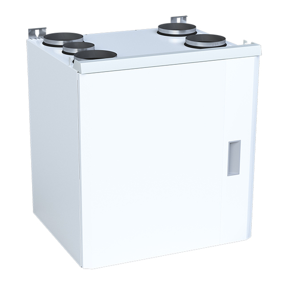
TECHNICAL SPECIFICATIONS OF THE UNIT Right-handed CHC connection cable with plug inlets for external sensors motherboard type plate extract filter heat exchanger extract fan inlet filter supply fan condensate connection G1/4" internal thread heat exchanger drive belt heat exchanger motor Width 600 mm Depth... -
Page 8: Duct Connections
5-duct Checking the handedness from the type plate Type label 1 2 3 4 5 6 7 8 9 0 Ventilation unit Svea eAir E TYPE: IP 44 W/ V/ HZ/ A: 1141/230,1~/50/6.1 www.enervent.com... -
Page 9: Before Installation
WOULD YOU LIKE TO KNOW MORE? If you would like to know more about the construction of ventilation systems and the insulation of ventilation ducts, you can read about them on our website at www.enervent.com. Installation instructions for professionals... -
Page 10: Building A Ventilation Ductwork
NOTE and customer satisfaction. The performance capacity of the ventilation unit and its evaluated heating or cooling power can be calculated with the Enervent Ventilation ducts must be closed until the ventilation system is commissioned, so that warm Energy Optimizer program on the Enervent website. We air does not flow into the ducts. - Page 11 Examples of ventilation duct insulation Extract air duct Soundproofing is not included in these insulation Warm space: instructions and examples. • Basic ventilation does not require insulation. Cold/semi-warm* space: • In basic ventilation, the insulation must be planned NOTE and implemented so that changes in the temperature of airflow are less than 1°C.
-
Page 12: Electrical Connection Requirements And Preparations
For more information, see done by sliding the DIP slide switch 2 down and then the control schematics at www.enervent.com. The up again. Check for more information from the electrical location has to be on a straight part of the duct, and schematic on page 53. - Page 13 the panel can start. Panel shows that it is trying to connect to the network. Press Re-connect the radio > Reset. The control panel connects itself to the wall mount. Connecting the indoor temperature sensor to the wall mount (extra) An indoor temperature sensor must be connected to the ventilation unit, if the ventilation unit is to be used for controlling indoor temperature.
- Page 14 The functions and extras listed in the following table may require external wiring or connecting to work. Location on eAir Voltage/current Cable example External wiring of controller card the ventilation unit AI NTC Room temperature sensor TE20/ Connector in the 3.3 VDC KLM 2X0.8 TE21...
- Page 15 Location on eAir Voltage/current Cable example External wiring of controller card the ventilation unit Free AI13 0–10 VDC KLM 4x0.8 (program-defined) Free AI14 0–10 VDC KLM 4x0.8 (program-defined) Free AI15 0–10 VDC KLM 4x0.8 (program-defined) Free AI16 0–10 VDC KLM 4x0.8 (program-defined) Analog outputs (AO) Cooling control voltage /...
-
Page 16: Installation
INSTALLATION Necessary additional installation materials NOTE Before installing the ventilation unit, make sure Material Intended use there are no foreign objects inside the ventilation Screws Mounting the rear attachment list unit or in the ducts and ventilation unit on a wall (for suitable models). -
Page 17: Wall Mounting
FOR INFORMATION Before installing the ventilation unit, check that the unit and the ductwork do not have any foreign objects inside them. Wall mounting 65kg 1/4" internal thread Installation instructions for professionals... -
Page 18: Draining Condensate Water
Installation of K900010002 water trap. Install the water trap to a 32 mm pipe and tighten the pipe connec- All Enervent ventilation units should be drained. If the tions. Observe the arrow on the water trap indicating correct direction of flow. The water trap can be instal- ventilation unit is equipped with active cooling, then led either vertically or horisontally (pic. -
Page 19: Installing Eair Control Panel
Installing eAir control panel The eAir control panel (See section “Control system and eAir control panel” ) is installed on a mounting box, or installed with a surface installation box (optional extra). Maximum two external control panels can be connected to a ventilation unit. Installation instructions for professionals... - Page 20 Optional extra 1-2 min...
-
Page 21: Installation To A Modbus Network
Maximum two TCP/IP connections can be active at TULO the same time. +12V MODBUS-RTU Modbus registers can be found on the Enervent website at www.enervent.fi. NOTE WARNING The Modbus TCP/IP connection method does not allow any kind of authentication or encryption. The... -
Page 22: General Instructions
Using the eAir control panel General instructions Ventilation is used primarily with modes. The modes in use NOTE can be seen in the control panel main screen. The user can choose the best mode for each situation: At Home, Away, Boost, Overpressure, Silent, or Max. -
Page 23: Functional Description
Functional description first rotating heat exchanger. This procedure significantly reduces the energy need foor cooling in hot and humid conditions. Operating environments Fans The operating environments for the ventilation unit are Home, Office, VAK1, VAK2, and VAK3. When electricity is connected to the ventilation unit, the damper control relay activates and heat recovery starts The functions available differ based on the operating at maximum efficiency. - Page 24 Carbon dioxide, humidity, and Overtime length is configured in the control panel. temperature boost of fans It can be activated from the control panel or from a separate button (optional extra). Overtime control can be The fan power of the ventilation unit is controlled based interrupted from the control panel.
- Page 25 Weekly and annual programs stops, when the outdoor temperature drops below the extract air temperature. This helps in keeping inside air cool in the summer. Time programs can be used to activate a user mode at a certain time on certain weekdays, or for some calendar days.
- Page 26 Filter guard (optional extra) Room temperature control requires that the unit has either a temperature sensor (optional extra) connected to the eAir control panel or a room temperature transmitter The ventilation unit can be fitted with a filter guard (optional extra) connected to the eAir motherboard. function as an optional extra.
-
Page 27: Commissioning
COMMISSIONING Requirements Adjusting air flow When the unit has been startedup, the air flows must be Functioning requirements of the ventilation unit: configured to designed values. • Supply and extract air temperature less than +55°C. • Air flows are adjusted when commissioning the •... -
Page 28: Control System And Eair Control Panel
Control system and eAir control panel Installing the battery The battery is not installed inside the control panel when delivered. It must be put in place before charging the panel. Open the battery case cover from the backside of the control panel. - Page 29 1-2 min The setup wizard starts automatically when the ventilation system is powered up for the first time. Important information on the control system All the settings configured with the wizard are active FOR INFORMATION immediately. Note: The code for the setup wizard and the The changes are automatically saved in the unit’s long- system settings is 6143.
- Page 30 The eAir operatin panel starts automatically and the Alarms cannot be acknowledged in the setup wizard. Enervent logo appears on the screen. If there is an alarm during the setup wizard, it can be Wait for the language choice to appear.
-
Page 31: Setup Wizard
Setup wizard NOTE! Factory settings are suitable for most installations. The fan speed settings for different operating modes are installation specific and must be specified and set separately for each installation. Do not change other factory settings, unless otherwise specified in the ventilation system plan. DISPLAY MENU SUB MENU... - Page 32 Home The options are Home or Office. In Office mode, the unit can be switched on only by using a time program. Temperature control Supply air Supply air maintains the supply air temperature at Extract air is the the value specified on the main view. This is the default setting for default setting for units with no cooling functionality.
- Page 33 Analog input 1 %RH sensor1 Define the functionality and set the voltage for the analog inputs 1-6 on the eAir motherboard. AI settings needs to be configured if there are external sensors connected to the ventilation unit, besides the two RH% and CO₂ sensors that are preconfigured.
- Page 34 Defrost Options are ON/OFF. The function is active during winter season, if enabled. When defrosting is active, the rotating heat recovery wheel will rotate at a slower speed. Limit temperature 8°C When the outside temperature is below this value, for winter boost the heat recovery is always on 100%.
- Page 35 Weekdays Every day Set the weekday or days for summer night cooling. Active cooling Options are ON/OFF. If this setting is on, no active blocked cooling is allowed. Supply air 20 % This value defines the supply air fan speed in Away operating mode.
- Page 36 Boost functions % RH boost Options are ON/OFF. This setting allows or prohibits boosting according to the air humidity. Summer / winter 4°C When the 24 hour mean temperature of outside air limit temperature is higher than this limit, boosted ventilation based on the 48 hour mean humidity of extract air is taken into use.
- Page 37 Temperature boost Options are ON/OFF. Select temperature Extract air The options are Extract air temperature or Room temperature temperature average. To be able to select room temperature average, you need a separate room temperature sensor (optional extra). Max. supply air fan The maximum allowed speed of the supply air fan speed during temperature boosting.
- Page 38 Modbus and eAir web settings Modbus ID Each device that is connected to the Modbus needs a unique identification. Modbus speed 19200 The options are 19200, 115200 or 9600. Modbus parity None The options are None or Even. Modbus TCP/IP Options are ON/OFF.
-
Page 39: Settings That Are Not Defined In The Setup Wizard
Settings that are not defined eAir motherboard connections in the setup wizard AI8 (X29) Extract air temperature TE30 Analog inputs AI9–AI16 are between 0–10V. These input functions are locked by the software. The ventilation units are pre-prepared at the factory AI9 (X10) Supply air filter pressure difference PDE01 (extra) in order to shorten the installation time. - Page 40 eAir motherboard connections DI5 (X15) Away mode. user-defined DI6 (X15) Overpressure, connected to push button switch. user-defined Overpressure mode is active for 10 minutes, from activation (factory setting). If the input is connected to a switch, the overpressure mode is re-activated only after the circuit is broken.
-
Page 41: Documenting The Commissioning
X1-X7, X12 Sensors Ethernet RHT30 eAir MOTHERBOARD RHT30 +24V DI10 POISTO TULO MODBUS-RTU AO analog DI digital inputs AI analog inputs DO digital outputs outputs eAir motherboard connections and their locations When you want to set unit settings, tap the upwards arrow in the main screen >... -
Page 42: Troubleshooting
TROUBLESHOOTING In case of an alarm Alarm Reason Instruction Solution HRW supply Heat exchanger belt is A green belt drives the heat exchanger. Check Change the belt. air cold broken if the belt can be seen from the HRW round (TE-05 min) opening. - Page 43 Alarm Reason Instruction Solution Supply air The HRW controller circuit The HRW motor is controlled by a separate Contact service. cold (TE-10 board is faulty circuit board that is located in the electric box min) of the unit. After heating is disabled Check if after heating is allowed and eco- Change settings if needed mode is off, and there is no heating block...
- Page 44 Alarm Reason Instruction Solution Water The heat exchanger belt is A green belt drives the heat exchanger. Check Change the belt radiator oily and slips from the HRW round opening if the pulley is freezing risk rotating even though the HRW rotor is not. (TE-45 min) Extract air fan has stopped Open the service hatch.
- Page 45 Installation instructions for professionals...
-
Page 46: Eu-Declaration Of Conformity
+358 207 528 800, fax +358 207 528 844 enervent@enervent.com, www.enervent.com Description of the product: Ventilation unit with heat recovery Svea eAir E Right Trade name of the product: The products are in conformity with the following standards: EN 60335-1:2012/A13:2017/A1:2019/A14:2019/A2:2019 EN 62233:2008/AC:2008... -
Page 47: Product Information According To Eu Kommission Regulation (Eu) N:o 1253/2014 Ja 1254/2014
Enervent Svea PRODUCT INFORMATION ACCORDING TO EU COMMISSION REGULATION NO 1253/2014 AND 1254/2014 Supplier’s name or trade mark Enervent Supplier’s model identifier Svea Specific energy consumption (sec) in kWh/(m • Cold climate -76,8 • Average climate -37,3 • Warm climate... -
Page 48: Energy Label
SVEA 619 m ENERGIA · ЕНЕРГИЯ · ΕΝΕΡΓΕΙΑ · ENERGIJA · ENERGY · ENERGIE · ENERGI 2016 1254/2014... - Page 49 Installation instructions for professionals...
-
Page 50: Appendices
APPENDICES Dimensional drawings Technical dimensional drawing, 5-duct right-handed 50 50... - Page 51 Installation instructions for professionals...
-
Page 52: Electrical Diagrams
Electrical diagrams Connections 52 52... - Page 53 External connections Installation instructions for professionals...
- Page 54 Internal connections...
- Page 55 Installation instructions for professionals...
- Page 56 Constant duct pressure control 56 56...
- Page 57 Installation instructions for professionals...
- Page 58 Filter guard 58 58...
-
Page 59: Sensors
Sensors Nimi / Namn / Selitys / Definition / Definisjon / Definition Navn /Name TE01 Ulkoilma / Uteluft / Temperatur uteluft / Outside air TE02 Ulkoilma esilämmittimen jälkeen / Uteluft efter förvärmare / Forvarmet utelufttemperatur, ekstern forvarmer / Outside air after preheater TE05 LTO jälkeinen tuloilma / Tilluft efter VVX / Temperatur etter varmegjenvinning / Supply air after HRW... - Page 63 Installation instructions for professionals...
- Page 64 Enervent Zehnder Oy Exvent AS Kipinätie 1 Ringeriksvei 195 FIN-06150 Porvoo, Finland N-1339 Vøyenenga, Norge Tel. +358 207 528 800 Tlf 67 10 55 00 enervent@enervent.com exvent@exvent.no www.enervent.com www.exvent.no...
Need help?
Do you have a question about the Svea eAir and is the answer not in the manual?
Questions and answers