Table of Contents
Advertisement
Advertisement
Table of Contents

Subscribe to Our Youtube Channel
Related Manuals for enervent greenair Plaza eco EC


Summary of Contents for enervent greenair Plaza eco EC
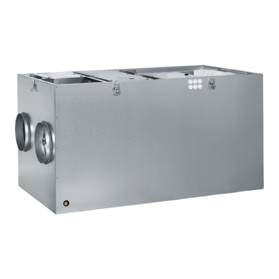
- Page 1 Enervent greenair ® Ventilation unit with heat recovery Planning, installation and operational instructions manual Before installing and operating this unit, please read this manual thorougly, and retain it for future reference. Electronic Climate Control www.enervent.fi...
-
Page 2: Table Of Contents
TABLE OF CONTENTS OVERVIEW TYPE MARKING TYPE DESCRIPTION FOREWORD OPERATING PRINCIPLE WARNING INSTALLATION DUCT HEAT INSULATION EQUIPMENT INSTALLATION USER GUIDE USER GUIDE Starting the unit Supply and exhaust air calibration About ventilation Control panel CONTROL MAINTENANCE MAINTENANCE BELT REPLACEMENT SERVICE/ALARM INDICATION TROUBLESHOOTING TECHNICAL INFORMATION TECHNICAL INFORMATION... -
Page 3: Type Marking
This manual covers the following units: ventilation unit Enervent® greenair Plaza (eco) EC(E) Enervent® greenair Pingvin (eco) EC(E) TYYPPI/TYPE: Enervent® greenair Pingvin eco XL EC(E) SRJ.NRO/SERIAL NO: Enervent® greenair Pandion (eco) EC(E) W/ V/ HZ / A: Enervent® greenair Pelican (eco) EC(E) Enervent®... -
Page 4: Operating Principle
OPERATING PRINCIPLE The ventilation units are based on regenerative heat recovery. This is achieved with a rotating heat exchanger through which incoming air and exhaust air flow in opposite directions. Aluminium foils within the heat exchanger transfer heat from the exhaust air to the supply air. A characteristic of the regenerative heat exchanger is its high rate of heat recovery (or efficiency). -
Page 5: Equipment
EQUIPMENT INCLUDED IN THE DELIVERY OF THE UNIT: Enervent® greenair ventilation unit Control panel * Control panel cable RJ11, length 20 m (installation in a min 16 mm conduit) * SEPARATELY SOLD EXTRA EQUIPMENT: Control panel ECC-05(E), max. 1+4 panels can be connected to the unit. -
Page 6: User Guide
LTR-3, LTR-6 and LTR-7 Place the unit on the insulation plate (i.e. 100 mm insulation covered with chipboard) in a storage room or in the attic on a custom made shelf. Take into consideration the possible need for a drain. Check that there is enough free space on top (above the service hatch) (LTR-3 min. -
Page 7: About Ventilation
LED will flash if supply air temperature drops below +5°C. It will also flash if the electrical heater’s over heating protection has tripped, emergency stop is activated (if one is connected) or an external alarm is active (if connected). Enervent® ECC EN 2010_2... -
Page 8: Control
CONTROL EXTERNAL CONTROL The units can be controlled externally with digital inputs i.e from a building automation or management system. The exter- nal commands will be updated to each of the control panels in the ventilation unit. The unit can be controlled either from the panels or externally and the last command will stay active. -
Page 9: Maintenance
Cleaning the fans When changing filters, also check the condition of the fans. If cleaning is required the fans can be removed from the unit and cleaned with a toothbrush or compressed air. Enervent® ECC EN 2010_2... - Page 10 Changing of filters The recommended time between filters changes is max. four (4) months for plain filters and max. six (6) months for bag filters. If class EU5 bagfilters are used the time between filter changes can be prolonged to one (1) year, by vacuuming the filters on the inside.
-
Page 11: Belt Replacement
Turn on the ventilation unit and check that the heat exchanger is rotating. Close the maintenance hatch. NOTE! A spare belt is delivered with the ventilation unit, it is attached to the inside of the heat exchanger. pic 5 Enervent® ECC EN 2010_2... -
Page 12: Service/Alarm Indication
SERVICE / ALARM INDICATION RED LED LIGHT LED: VENTILATION UNIT: SWITCH OFF THE ALARM: LED is on: works normally ventilation unit main - filter change reminder power switch LED is flashing: exhaust air fan is on speed 1, - supply air temperature after automatically, when supply air fan and HRW are off temperature is above +5°C... -
Page 13: Technical Information
F1 T1,6 A F1 T3,15 A F1 T5 A F1 T8 A Heat exchanger motor rating 8 W, 0.035 A 8 W, 0.035 A 8 W, 0.035 A 8 W, 0.035 A 8 W, 0.035 A Enervent® ECC EN 2010_2... - Page 14 VENTILATION UNIT: PLAZA PINGVIN 85 PINGVIN 120 PINGVIN XL Width 598 mm 580 mm 580 mm 780 mm Depth 320 mm 500 mm 500 mm 555 mm Hight 630 mm 540 mm 540 mm 540 mm Weight 45 kg 50 kg 50 kg 63 kg Duct connections...
-
Page 15: Dimension Drawings
DIMENSION DRAWINGS Enervent® ECC EN 2010_2... - Page 17 Enervent® ECC EN 2010_2...
- Page 19 Enervent® ECC EN 2010_2...
- Page 21 Enervent® ECC EN 2010_2...
- Page 23 Enervent® ECC EN 2010_2...
-
Page 24: Heat Recovery Efficiency
HEAT RECOVERY EFFICIENCY... - Page 25 Enervent® ECC EN 2010_2...
-
Page 27: Characteristic Curves
CHARACTERISTIC CURVES Enervent® ECC EN 2010_2... - Page 29 Enervent® ECC EN 2010_2...
- Page 31 Enervent® ECC EN 2010_2...
- Page 33 Enervent® ECC EN 2010_2...
- Page 35 Enervent® ECC EN 2010_2...
-
Page 37: Outer Wiring
Quick Control for electrical after heater (ECE-models) AFT HEAT Quick Control for electrical after heater (ECE-models) AFT HEAT Quick Control for electrical after heater (ECE-models) AFT HEAT Quick Control for electrical after heater (ECE-models) AFT HEAT Enervent® ECC EN 2010_2... - Page 38 WIRING, max. 250 V max. 250 V Connector type Internal Connector External Screw Earth to the AHU Screw Neutral to the AHU Screw To Door switch / Main switch Screw 230 VAC, 50 Hz supply to the AHU Screw To Door switch / Main switch Screw From Door switch / Main switch Screw...
-
Page 39: Wiring Diagrams
WIRING DIAGRAMS Enervent® ECC EN 2010_2... - Page 41 The defrosting function is activated by short circuiting the defrosting pins on the main board. The defrosting is in active when the unit leaves the factory. ECC units (with alternating current fans): Defrosting Defrosting inactive active TEMP eco ECC units (with direct current fans): J1 J2 Defrosting active Enervent® ECC EN 2010_2...
- Page 43 MAX. 4 kW Enervent® ECC EN 2010_2...
-
Page 44: Declaration Of Confirmity
Description of the product: Ventilation unit with heat recovery Trade name of the product: Enervent® greenair Plaza eco EC(E) Enervent® greenair Pingvin (eco) EC(E) Enervent® greenair Pingvin eco XL EC(E) Enervent® greenair Pandion (eco) EC(E) Enervent® greenair Pelican (eco) EC(E) Enervent®... -
Page 45: Warranty Conditions
I WARRANTY CONDITIONS 04/2010 appropriate installation rights; The equipment has been repaired by a party other than Enervent Oy or a contractor with the 1. Enervent Oy grants a warranty on products (hereinaf- appropriate installation rights; ter ”equipment”) manufactured and marketed by the The equipment has been installed or repaired company.
Need help?
Do you have a question about the greenair Plaza eco EC and is the answer not in the manual?
Questions and answers