
Related Manuals for Panasonic LP-ABR10 Series


Summary of Contents for Panasonic LP-ABR10 Series
- Page 1 Code Reader Setup / Operation Manual LP-ABR10 series Please read these instructions carefully before using this product, and save this manual for future use. ME-LPABR10-SO-5 2020.11 panasonic.net/id/pidsx/global...
- Page 2 Preface Thank you for purchasing our product. For full use of this product safely and properly, please read this manual carefully. This product has been strictly checked and tested prior to its delivery. However, please make sure that this product operates properly before using it.
-
Page 3: Safety Notices
The use of this product shall indemnify and hold harmless to Panasonic Industrial Devices SUNX's and its shareholders against any claims of injury or death associated with unintended authorized use. -
Page 4: Handle With Care
Handle with care This product has a memory backup function. This backup data restoration cannot be guaranteed if repair, reconstruction, or upgrades are performed on this product. DO NOT use this product at temperature or humidity ranges beyond that documented in the product specifications, or in direct sunlight. -
Page 5: General Terms And Conditions
Products) as occasioned by the improvements of Products. Consequently, when you place orders for these Products, Panasonic Industrial Devices SUNX asks you to contact one of our customer service representatives and check that the details listed in the document are commensurate with the most up-to-date information. - Page 6 SCOPE OF WARRANTY In the event that Panasonic Industrial Devices SUNX confirms any failures or defects of the Products by reasons solely attributable to Panasonic Industrial Devices SUNX during the warranty period, Panasonic Industrial Devices SUNX shall supply the replacements of the Products, parts or replace and/or repair the defective portion by free of charge at the location where the Products were purchased or delivered to your premises as soon as possible.
-
Page 7: Applicable Standards
Applicable standards This product conforms to the following standards. Note that our products do not conform to the safety standards of the countries and regions not listed in the applicable standards section. When exporting the product by itself or integrated into machine or device, confirm the regulations and standards of the exporting country or region. -
Page 8: Unpacking
Unpacking Before unpacking the LP-ABR series Code Reader check that there has been no damage to the packaging. Check that the box includes the items listed below. If any items are missing or damaged, contact our local sales representative. Included items Item Qty. -
Page 9: Download Information
Download Information The user manuals, software, and device drivers are available from: http://industrial.panasonic.com/ac/e/fasys/lasermarker/lasermarker/lp-abr10/index.jsp LP-ABR10 series Setup/Operation Manual: Describes the features, specifications, configuration and operation of the Fixed mount 2D Code Reader LP-ABR. Configurator LP-ABR: Is a software for the various settings and decoding check on your computer. -
Page 10: Table Of Contents
Table of Contents Safety notices ....................... 3 Handle with care ....................4 General Terms and Conditions ................5 Applicable standards .................... 7 Unpacking......................8 Included items ...................... 8 Optional items ....................... 8 Lineup ........................8 Download Information ................... 9 Overview ....................... 13 Supported Symbologies .................... - Page 11 Configuration parameters ....................35 Reading Parameter ......................41 Camera Control Mode ..................... 46 Detail of Table Mode ......................47 Advance Features ..................49 Preset Mode ........................49 Output Additional Information ..................53 Save Image ........................60 PLC Link .......................... 63 Simultaneous reading of multiple labels ................
- Page 12 7.11 Configuration Reference ....................92 7.12 Image Output and Image Storage ................... 92 7.13 LAN Settings ........................93 7.14 Symbol Printing Check ....................94 7.15 General Operation ......................95 7.16 Table of Character Code ....................95 Specifications ....................96 Specifications ........................96 Reading Specifications ....................
-
Page 13: Overview
1 Overview (1) This products is fixed mount (stationary type) Code Reader capable of two-dimensional (2D) codes. These units incorporate the most innovative digital camera technologies, related image recognition, and processing software. A powerful high-speed processing engine equipped with a dual-core CPU is adopted on the Fixed mount 2D Code Reader LP-ABR. -
Page 14: Supported Symbologies
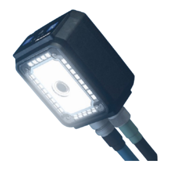
Supported Symbologies 2D Codes Data Matrix (ECC200) QR Code Product Description Regular Type Serial Number Label MAC Adderss Label Operation Panel Control Connector Reading Window LAN Connector Front Cover Long Range Type Front Cover Reading Window... - Page 15 1.2.1 Operation Panel The operation panel consists of an action display monitor and 2 operation keys. Act-LED Link-LED Teach Key Read Key Monitor LED A to D Fucntion of Monitor LED Color Name Description of Function Turns on when Code Reader is operatable. Ready Blinking when the "SYNC IN by trigger area"...
- Page 16 1.2.2 Code Reader Connector (17 pins) Code Reader Connector is used for connecting the power supply and digital input/output with your Code Reader. Power Input Power input of LP-ABR supplies DC24V. 4 Digital Outputs: LIGHT, OUT1, OUT2 and OUT3 The 4 Digital outputs are digital signal outputs with photo-coupler isolation.
- Page 17 Digital input (SYNC input): This signal is a photo coupler isolated input which is used for synchronous inputs. [Plug the connector] ① Adjust the positions of the guide part of the cable nut and the marking of the resin ②...
- Page 18 1.2.3 LAN Connector (8 pins) This connector is used for connecting the LAN cable (optional) of LP-ABR series with your Code Reader. [Plug the connector] ① Adjust the positions of ② the guide part of the cable nut and the marking of the resin part.
- Page 19 1.2.4 Internal illumination unit Internal illumination unit illuminates the central part of Code Reader from inside the front cover. Illumination unit consists of a block: CENTER which is adjacent to reading window and four blocks: TOP, BOTTOM, LEFT, and RIGHT. Each block's illumination brightness and light on/off are controlable.
-
Page 20: How To Use
2 How to use Preparation ① Establish a communication between the reader and the host device through RS-232C interface/LAN interface. Connect a control device as needed. <Example of Connection> LP-ABR LAN Cable Host Device LAN Connector PC, etc. Control Connector Control Device Control (e.g. - Page 21 ② Supply power from the interface cable to the reader. The LED-A (Ready) turns on (red) if the reader is correctly powered. A combination of 2 long beeps and 3 short beeps will indicate that the reader has started up correctly. ③...
-
Page 22: Reading Flow (Default)
Reading Flow (Default) Good Read 1 short beep Symbol’s data will be sent through the interface (RS232C, LAN). Digital output “GO” is ON. LED-C (GO) turns on (green). Note: The activated period of “GO” and the monitor LED-C can be configured through serial commands. -
Page 23: Operation Mode
3 Operation Mode LP-ABR has can be operated in following 2 modes. Operational Mode Command Description Single Reading Mode SYNCMODE=0 Single read for each SYNC input. Reading Timeout Mode SYNCMODE=1 After SYNC input, the reader continues reading during the duration time set by “TOTALLIM”. -
Page 24: Single Reading Mode
Timing Chart DELAY: The time from SYNC ON to reading. CHATT: The time needed for eliminating the chattering. IMAGE: The time duration for capturing an image. DECODE: The time duration for decoding. DECODELIM: The maximum time limit for decoding. GOOUT: The length of time the GO signal is asserted. - Page 25 3.1.2 Hard trigger, Good Read, Data transmission: After decode SYNC DELAY image1 IMAGE DECODE decode1 DECODELIM SERIAL GOOUT GOOUT CHATT 3.1.3 Hard trigger, No Read, Data transmission: After decode SYNC DELAY image1 IMAGE decode1 DECODE DECODELIM SERIAL NGOUT NGOUT CHATT...
-
Page 26: Reading Timeout Mode
Reading Timeout Mode Code Reader reads the symbol repeatedly during the duration time, set by “TOTALLIM” after the SYNC input, or continues reading until the decoding is successful. If the reader cannot decode successfully in the duration time, it stops reading and sends an error code to the host. Typically MAXIMG is set to a number greater than one. - Page 27 3.2.3 Hard trigger, Good Read, Data transmission: After decode WAITIMG WAITIMG WAITIMG WAITIMG SYNC DELAY image1 image2 image3 image4 image5 IMAGE decode1 decode2 DECODE DECODELIM DECODELIM SERIAL TOTALLIM GOOUT GOOUT CHATT 3.2.4 Hard trigger, Good Read, Data transmission: After SYNC OFF WAITIMG WAITIMG WAITIMG...
- Page 28 3.2.5 Soft trigger, No Read, Data transmission: After decode WAITIMG WAITIMG WAITIMG WAITIMG SYNC DELAY image1 image2 image3 image4 image5 IMAGE DECODE decode1 decode2 DECODELIM DECODELIM SERIAL TOTALLIM NGOUT NGOUT 3.2.6 Soft trigger, No Read, Data transmission: After SYNC OFF WAITIMG WAITIMG WAITIMG...
- Page 29 3.2.7 Hard trigger, No Read, Data transmission: After decode WAITIMG WAITIMG WAITIMG WAITIMG SYNC DELAY image1 image2 image3 image4 image5 IMAGE DECODE decode1 decode2 DECODELIM DECODELIM SERIAL TOTALLIM NG-OUT NGOUT CHATT 3.2.8 Hard trigger, No Read, Data transmission: SYNC OFF WAITIMG WAITIMG WAITIMG...
-
Page 30: External Trigger Mode
External Trigger Mode Code Reader reads the symbol repeatedly during the SYNC input is active. Typically MAXIMG is set to a number greater than one. The multiple MAXIMG enables the Cycle Buffer Function and the simultaneous parallel processing between image import and decoding. - Page 31 3.3.3 Hard trigger, No Read, Data transmission: After decode or SYNC OFF SYNC WAITIMG WAITIMG WAITIMG WAITIMG DELAY image1 image2 image3 image4 image5 IMAGE DECODE decode1 decode2 decode3 DECODELIM DECODELIM SERIAL NG-OUT NGOUT CHATT CHATT...
-
Page 32: Continuous Reading Mode
Continuous Reading Mode In Continuos Reading Mode the reader read repeatedly. It is used for camera tunings. To put the reader in Continuous Reading Mode, send the serial command “continue” to the reader, and then send the serial command “g” to start reading. To exit the Continuous Reading Mode, send the serial command “stop”... -
Page 33: Cycle Buffer Function
Cycle Buffer Function With cycle buffer function, the reader images the target serially when the positions of moving targets are scattered against the SYNC. In SYNCMODE=1 (Reading Timeout Mode) or SYNCMODE=2 (External Trigger Mode), the Cycle Buffer Function is enabled when the MAXIMG number is greater than 1one (default is four 4). - Page 34 [Concept of using Cycle Buffer] The greatest feature of this function is the imaging of the predetermined number at a constant time interval unrelated to reading processing time. Set the number of imaging within the MAXIMG setting (16 sheets maximum) for the imaging at regular intervals. Otherwise the imaging interval will vary depending on the reading processing time after the number of imaging.
-
Page 35: Configuration For Symbol Reading
4 Configuration for Symbol Reading Configuration parameters This function is for automatic confituration of reading parameter. With this function, you can configure a lot of complex parameters automatically.This function is available by the communication from the host device as well as an easy key operation on a lone Code Reader. - Page 36 ④ Press Read key while the result is displayed to save the result of successful auto tuning. The result of setting changes depending on the length of time you press the button. Less than 2 seconds (Table Mode): Saves 3 types of settings and uses them switching as needed. More than 2 seconds (Manual Mode): Saves 1 setting and uses it.
- Page 37 4.1.2 Commands Related to Auto-Tuning In Auto-Tuning, you can configure auto-tuning operation, reference of tuning result, selection of storing method and setting of tuning condition by communicating with the host. Set the shutter speed lower limit of auto-tuning. *SHUTTLIM=a Shutter speed 1/60 (Default) Shutter speed 1/125 Shutter speed 1/250...
- Page 38 Force-quit running auto-tuning *cancel Auto-tuning takes a lot of time. This command is used for canceling an auto-tuning. Code Reader force-quits the auto-tuning. Check the condition of LP-ABR *?state This command is used for checking the condition of your Code Reader. The answers from Code Reader are as follows.
- Page 39 Refer to saved result of tuning ?ddmtbl This command is used for saving a result of auto-tuning to the manual mode.
- Page 40 Output Example of ?ddmtbl <SID=0>[My Reader] +++++ table 4 +++++ ******** STATUS ******** LP-ABR DDMcapmode=0,0,1920,1200 last table number=-1(read only) DDMlight=3 next table number=1(read only) DDMled=1,1,1,1,1,1 STARTDDMTBL1=1 (0: OFF 1: ON) DDMbrightness=80,80,80,80,80,80 ENABLEDDMTBL=8 (1-8) DDMshutt=2 EDITDDMTBL=0 (1-8) DDMgain=3 TBLTX=0 (0: OFF 1: ON) DDMblack=0 +++++ table 0 +++++ DDMexgain=1...
-
Page 41: Reading Parameter
Reading Parameter Configure the following parameter if Auto-tuning does not work or when you want to tune Code Reader manually. This parameter exists for each table of the table mode which is described later. Set this parameter to the table of your Code Reader. Code Reader operates referring to the parameter in table 0 if the setting is configured to not use the table mode. - Page 42 4.2.1 Reading Area (1) Reading Area [DDMcapmode] This function is used for specifying a readable area from an image. The reading area is specified depending on the X origin, y-coordinate, width and height. [0,0] [a,b] Imaging Area [1279,959] Maximum Imaging Area DDMcapmode=a,b,c,d a: Coordinate origin X (0-1275) b: Coordinate origin Y(0-955)
- Page 43 4.2.2 Illumination (2) llumination control (ON/OFF) [DDMlight] This command is used for configuring how the internal/external illumination illuminate. DDMlight=a (a: 2,3) 2: Internal illumination OFF when capturing an image 3: Internal illumination ON (with pulsed operation) when capturing an image 4: External Illumination ON when capturing an image 5: External Illumination ON always 6: External Illumination ON during synchronization...
- Page 44 4.2.3 Shutter Speed (5) Shutter Speed [DDMshutt] Configures the shutter speed. If the image is still dark even with the illumination, configure the shutter speed slower to brighten the image. Note that this may cause a blur. The following 10 speeds can be specified.
- Page 45 4.2.5 Black Level Adjustment (8) Black Level Adjustment [DDMblack] This is a reserved parameter. Set it to 0 always. DDMblack=0 4.2.6 Image Preprocessing (9) Image Preprocessing [DDMpreproc] If the image quality is low, by using an appropriate image filter at the image preprocessing may improve the reading accuracy 4.2.7 Mirrored Image (10) Mirrored Symbol [DDMmirror]...
-
Page 46: Camera Control Mode
Camera Control Mode Camera Control Parameter consists of tables whose reading parameters are stored in and a camera control mode which operates tables. Camera Control Mode Table Table #0 Fixed gain: D Table #1 Table #2 Table #3 Table #4 Table: Table #5 Table #6... -
Page 47: Detail Of Table Mode
Detail of Table Mode Up to 8 tables can be used while the trigger is activated. ENABLEDDMTBL=a (a: 1 to 8) e.g.1) Use 3 tables (a=3) Table #1, #2 and #3 are enabled and Table #4 through #8 will not be used. If the reader successfully decodes a symbol with Table #1, Table #1 will be used in the next reading. - Page 48 When the reading is successful, the reader uses the table setting in the next reading. When the reading is failure, the reader attempts to read using the next table setting. The flow chart of Table mode is shown below. < Flow char of Table Mode > Trigger Use this Table Read OK?
-
Page 49: Advance Features
5 Advance Features Preset Mode In Preset mode, LP-ABR series read only the symbols whose data match the preset data. This function has 2 modes whose registration method and data collation method of preset data are different. PREM=0[CR](*): Preset Mode 0 (Preset Mode is disabled) PREM=1[CR]: Preset Mode 1 (Preset data is the first decoded one after power up) PREM=2[CR]:... - Page 50 5.1.2 Preset Mode 2 In this mode, the preset data is configured by the serial command. Data comparison is completed by both complete and partial matching. It is possible to save the preset data to internal flash memory. Send the following command to set this mode: PREM=2[CR] : Set the preset data (data is “abcd”) SET=PREDabcd[CR]...
- Page 51 e.g.3) Example 3: Valid when the length is 10 digits and the data from 3rd-digits to 6th-digits are “ALFA”. 00ALFA1234 : match AAALFAAAAA : match 00ALFA12345 : mismatch 0ALFA12345 : mismatch PREM=2[CR] SET=PRED??ALFA????[CR]: Set the preset data (data is “??ALFA????” and “?”...
- Page 52 5.1.3 Output the status of Preset Mode ?pre[CR] : Output the preset status (Example output) PREM=0 (0: non 1: power on 2: saved) PRESET LENGTH: 13 DATA(HEX): 34 39 3F 3F 3F 3F 3F 3F 3F 3F 3F 3F 3F DATA(ASCII): 49??????????? (Output format)
-
Page 53: Output Additional Information
Output Additional Information 5.2.1 Output the scanned data adding Code Reader’s individual name It can be used for multi-configuration with the reader. Host computer can recognize the data which reader has sent. Set an individual name to each reader MYNAME=aaaa aaaa: (Alphanumeric strings from 1 to 31 digits) The name of all Code Readers is “My Reader”... - Page 54 “000” is added in case of No Read. 5.2.3 Symbol Type Information Add symbol type information (decoded symbol type) to the head of decoded symbol and output is in serial. Symbol Type is not added at No Read. Symbol Type Code Type Information Data Matrix QR Code...
- Page 55 5.2.7 Quality Information The percentage of the Unused Error Correction codeword of the 2D code is added to the decoded data. For example, if the decoder does not use any error correction, this value would be 100. The reader outputs the quality information individually if there are multiple symbols.
- Page 56 (Output format) Header + Data + (A1) + (A2) + (A3) + (A4) + Terminator A1 – A4 : (abbbb,acccc) : + or - bbbb: X coordinates of four corners of a symbol (-9999 to +9999) cccc: Y coordinates of four corners of a symbol (-9999 to +9999) (3) Barycentric / Rectangular coordinates Outputs coordinates of both barycenter and four corners of a symbol.
- Page 57 5.2.9 Table Number Table numbers given at read are added to sybmol data. (Example output) 10000000099070 (ddmtbl=3) (Output format) Header + Data + (ddmtbl=a) + Terminator a : Table number 5.2.10 BCC (Back Check Charactor) Calculates BCC (backcheck character) to detect errors. The calculated BCC is added to the symbol data.
- Page 58 CRC16 Calculates with all characters (excluding headers) by following method. CRC characters are used for the calculation. (Initial value: [0x00]) 1. The character is logically shifted 8 bits to the left 2. Calculates the total value in 1. and the CRC character by the exclusive OR.The calculated value is assigned to the CRC character.
- Page 59 5.2.11 Output data length Adds output data length given at reading excluding the header, terminator and BCC to sybmol data. There are two types of output digits: 4 digits and 5 digits. If the number of digits of output data is less than 4 digits or 5 digits, add 0 to the beginning.
-
Page 60: Save Image
Save Image Up to 16 captured images can be stored by increasing the number of cycle buffers memory. Set number of cycle buffer memory is the number of storable images. MAXIMG=a[CR] a=1-16 Specifies number of cycle buffer memory. MAXIMG=1[CR] (*) *: Default 5.3.1 Save Preprocessed Image Selects an image to save from the 2 images captured before or after... - Page 61 5.3.4 Output status of image storage condition ?IMG[CR] Output setting status (Output Example) <SID=0>[My Reader] ******** STATUS ******** LP-ABR IMODE=0 PX=0 PY=0 WX=1920 WY=1200 CAPMODE=0,0,1920,1200 DECMODE=0,0,0,1920,1200 IMGSEL=1 (0: captured image 1: decoded image) CAPDLY=0 MAXIMG=1 (1-16) WAITIMG=100 (0-1000) CAPLIM=0 (0: OFF 1: ON) ********* END ********** LP-ABR System version = M66C-V0.1q Decode version = M66A-V0.1q...
- Page 62 : Trimming b,c,d,e : Trimming position (Left, Top, Width, Height) f,g,h,i : Capture area (Left, Top, Width, and Height) : Not link/link with capture area k,l,m,n : Decode area (Left, Top, Width, and Height) : Image type (Captured image, Decoded image) : Delay time after SYNC-ON to capture start (ms) : Number of cycle buffer memory : Overwrite/not overwrite the cycle buffer memory when the...
-
Page 63: Plc Link
PLC Link With PLC link, you can write a reading result of symbols directly to the PLC internal data memory (programable logic controller) through RS-232C or LAN interface. Simultaneous reading of multiple labels In symbol reading mode, multiple (up to 10) labels can be read simultaneously. The order of reading data output can be configured under following conditions. -
Page 64: Symbol Printing Check
Symbol Printing Check This function judges a printing quality of a two-dimensional symbol captured by Code Reader using in-line. It verifies the print quality and output the result by using evaluation parameters of ISO15415 or AIM DPM-1-2006. Printing quality of symbols flowing on manufacturing line is maintained at a certain level by being checked in-line. - Page 65 5.6.1 Supported Symbologies 2D Codes Data Matrix (ECC200) QR Code 5.6.2 Symbol Printing check Items to be output The evaluation values are output on a scale of 5 levels (0 to 4) by each evaluation items."Overall Quality" means a value of each element's lowest grade. (If there are 5 evaluation items and the determination value was 4,3,2,3,4, the overall quality is 2.
-
Page 66: Image Rotation
Image Rotation Rotates an image 180 degrees before a capture. The rotated image is used in all the process (decoding, saving data, etc) after the rotation. After the rotation, the layout of illumination blocks will be replaced as shown below. No image rotation (Default) Image rotation enabled [0,0]... -
Page 68: Internal Flash Memory Recovery Process
Internal flash memory recovery process If the power is turned off while saving the settings in the internal flash memory, the area where the settings are saved may be damaged. Image reader checks the status of the internal flash memory at startup and performs recovery processing if it is damaged. -
Page 69: Lan (Tcp/Ip) Connection
6 LAN (TCP/IP) connection Preparation Configure the network setting to use the LAN interface. Configure IP address 6.2.1 Configure through RS232C interface Connect the reader to a PC through a RS232C cable. Start a terminal software “Configurator LP-ABR” on a host computer. Operate entering various commands from the terminal software. -
Page 70: Default Settings
Turn off power and restart the reader 6.2.2 Configure through LAN interface Configure settings through LAN interface, if the IP address and the port number of the reader are known. Make sure the IP address of the superior computer is set into the same network as the reader. - Page 71 e.g.) Settings example IPADR=192.168.0.101/24 IPPORT=60000 GWADR=192.168.0.1 ?LAN <SID=10>[My Reader] ******** STATUS ******** LP-ABR IP address (IPADR) : 192.168.209.010 [>> 192.168.0.101] Sub net mask (/n) : 255.255.255.000 [>> 255.255.255.000] Default gateway (GWADR) : 192.168.209.254 [>> 192.168.0.1] Barcode port (IPPORT) : 27110 [>> 60000] Image port (IPPORT2) : 27110 [>>...
-
Page 72: Check For Lan Settings
Check for LAN settings 6.4.1 Through RS-232C interface LAN setting can be confirmed through RS-232C interface anytime. ?Confirm the LAN settings by the command below. ?LAN The following parameters are sent to the host: IP address Sub net mask Default gateway Port number of TCP server connection (only for reading result transmission) Port number of TCP server connection (only for image data transmission) Destination of TCP client communication (only for reading result transmission) -
Page 73: Connect To Lan
Connect to LAN Use a dedicated LP-ABR series LAN cable to connect. Auto-negotiation function which can automatically configure both communication speed (1Gbps, 100Mbps, 10Mbps) and communication mode (Full Duplex, Half Duplex) is mounted on the cable. Therefore, configure the LAN setting (communication speed and communucation mode) of your computer to auto-setting at a one-to-one communication through a crossover cable. - Page 74 [TCP client connection for transmission of reading result] The reader also works as a TCP/IP client whose access point (IP address: port number) can be set. Configure the connection timing by the command RTIME (Connection request interval). Connect every time when you send data Connect automatically every time the reader is powered on Once a connection is established, the reader will disconnect in the following cases.
-
Page 75: Serial Command For Lan Settings
[UDP Communication] Code Reader also works as an UDP server with a fixed port number (49460). The connectionless UDP communication can communicate with multiple superior PCs. When you send data in a broadcast from the superior PC, all devices on the LAN will respond. - Page 76 IPIMG=xxx.xxx.xxx.xxx: nnnn Destination IP address of image data: Configure the port number. Sends reading results from the TCP server when the destination IP address is 0.0.0.0. Sends reading results from the TCP client when the destination IP address is other than 0.0.0.0. xxx.xxx.xxx.xxx Destination IP address nnnn...
- Page 77 ?netstat Outputs following information in a line. Local IP address (IP address of the reader) Local Port number (TCP server port number of the reader) Remote IP address (IP address of the connected PC) Remote Port number (Port number of the connected PC) TCP/IP server socket status ?netstat IPBAR Outputs information about the destination of reading result in a line.
-
Page 78: Iinitialize Lan Address
Iinitialize LAN address If the configured address is unknown, send commands to start the reader with default setting through RS-232C im following steps: - Send a command SET=LAN. - Send a command WSETS. - Restart the reader. Default settings IP address : 192.168.209.10 Sub net mask : /24... -
Page 79: Serial Command (Rs-232C, Lan)
7 Serial Command (RS-232C, LAN) The following serial commands can be used through both RS232C and LAN (TCP/IP) interface unless otherwise specified. Serial command format Serial command + [CR] Default (Backward compatible) [Header] + Serial command + [Terminator] To add header and terminator characters to a serial command, send the command "CMDFORM=1". -
Page 80: Communication
Communication Term Command Description (*)=Default Baud rate BAUD=aaaa Baud rate of RS-232C aaaa=1200; 1200bps, aaaa=2400; 2400bps, aaaa=4800; 4800bps, aaaa=9600; 9600bps, (*), aaaa=19200; 19200bps, aaaa=38400; 38400bps, aaaa=57600; 57600bps, aaaa=115200; 115200bps, 7 bits, Odd, Stop bit 1 Frame FRAME=0 7 bits, Odd, Stop bit 2 FRAME=1 7 bits, Even, Stop bit 1 FRAME=2... -
Page 81: Symbologies
Symbologies Term Command Description (*)=Default Common SET=#M0 Disable all symbologies SET=#M1 Enable all symbologies SYMHEAD=#a Header character for all symbologies =#a,\bb a=0; Disable (*) a=1; Enable bb; Identifying character (Hexadecimal code (*1)) When omitting “bb”, configured identifier will not changed. SYMFOOT=#a Footer character for all symbologies =#a,\bb... - Page 82 Term Command Description (*)=Default DataMatrix SET=dM0 Disable DataMatrix Enable only for square shaped and normal DataMatrix SET=dM1 Enable only for square shaped and inverse DataMatrix SET=dM2 Enable only for square shaped and normal/inverse DataMatrix SET=dM3 Enable only for square/rectangle shaped and normal DataMatrix SET=dM5 Enable only for square/rectangle shaped and inverse DataMatrix SET=dM6...
-
Page 83: Symbol Reading (Operating Mode, Adjustment And Diagnostic)
Symbol Reading (Operating mode, adjustment and diagnostic) Term Command Description (*)=Default Start reading (SYNC ON) † The default setting is valid only RS-232C Reading BR=a interface No read message a=0 None, a=1 "BR"(*), a=2 "ERROR", a=3 "?" DECODELIM= Set the time limit for decoding process a=100 to 10000 [ms], 10[ms] step a=1000 [ms](*) Operation... - Page 84 Term Command Description (*)=Default Total time of TTTX=a (,b) a=0; Disable addition of TTTX for RS-232C(*) decoding a=1; Enable addition of TTTX for RS-232C b=0; Disable addition of TTTX for LAN(*) b=1; Enable Disable addition of TTTX for LAN Omit (,b): Set RS-232C and LAN in the same way (=a) Swing Value AGCTX=a (,b)
- Page 85 Term Command Description (*)=Default Symbol XYTX=a (,b) a=0; Disable output coordinate data to RS-232C (*) Position a=1 to 3; Enable output coordinate data to RS-232C Information b=0; ; Disable output coordinate data to LAN (*) b=1 to 3; Enable output coordinate data to LAN Omit (,b): Set RS-232C and LAN in the same way (=a) a=1;...
-
Page 86: Auto-Tuning
Auto-Tuning Term Command Description (*)=Default Auto-Tuning *setup Start Auto-tuning Cancel *cancel Cancel the running Auto-tuning Get status the running Auto-tuning STANDBY Reading standby RECEIVDED Auto-tuning Auto-Tuning *?state Waiting data save † SAVEWAIT(a) Status (None) Reading †(a) is the number of tuning results that can be saved. (a:1-3) Save Tuning Result *save... -
Page 87: Camera Control (1) (For Fixed Gain And Automatic Gain Control Mode)
Camera Control (1) (for Fixed Gain and Automatic Gain Control Mode) Term Command Description (*)=Default Set in fixed Set in Fixed Gain Mode (*) Camera Control AGC=D Mode AGC=T Set in Automatic Gain Control Mode CAPMODE= Capture area Left 0 to 1275 0 (*) Left, Capture area... -
Page 88: Camera Control (2) (For Table Mode 1)
Term Command Description (*)=Default Set the type of preprocessing to captured images Image IPFUNC0= a,b,c,d,e : Preprocessing commands(Described later) Preprocessing a,b,c,d,e a,b,c,d,e =0,0,0,0,0 (*) Up to 5 stage of function can be set by CSV a=0; Read only normal type (not mirrored) (*) Mirrored image MIRROR=a a=1;... -
Page 89: Camera Control (3) (For Table Mode 2)
Camera Control (3) (for table Mode 2) Term Command Description (*)=Default DDMcapmode= Specify capturing area of the table Left 0 to 1275 0 (*) Left, Capturing area Top, 0 to 955 0 (*) Width, Width 4 to 1280 1280 (*) Height Height 4 to 960 960 (*) -
Page 90: Image Preprocessing
Image Preprocessing Term Command Description (*)=Default None No Image Preprocessing Black Erosion Erosion 2x2 Erosion 3x3 Erosion 5x5 Erosion 2x1 (w) Erosion 1x2 (h) White Dilation Dilation 2x2 Dilation 3x3 Dilation 5x5 Dilation 2x1 (w) Dilation 1x2 (h) Reverse White & Black Reverse Contrast Cont(L12cut) : Trancates the 12% of dark side Enhancement... -
Page 91: Plc Link
7.10 PLC Link Term Command Description (*)=Default IP address and port number of IPPLC=xxx.xxx.xxx.xxx: Set the IP address and port number of Destination PLC Destination nnnn 192.168.0.10: 9600 (*) Start/Stop PLC Link function a=0; Exit PLC link mode (*) a=1; Mitsubishi MELSEC Q/L SeriesUDP MC protocol QnA compatible 3E frame(binary code) a=2;... -
Page 92: Configuration Reference
7.11 Configuration Reference Term Command Description (*)=Default Configuration Status transmission (First page) Reference Status transmission (Second page) Status transmission (Second page) † Old model-compatible command Status transmission (Third page) Status transmission (Third page) † Old model-compatible command Status transmission (Fourth page) Status transmission (Fifth page) Status transmission (Sixth page) ?IMG... -
Page 93: Lan Settings
7.13 LAN Settings Term Command Description (*)=Default Set to default for all LAN settings SET=LAN Settings Get the list of settings for LAN connection ?LAN IPADR=aaa.bbb.ccc.ddd/ee Set IP address and subnet mask 192.168.209.10/24 (*) Set Port number (Only for reading result transmission) IPPORT=aaaaa aaaaa=1-65535, aaaaa=27110 (*) Set Port number (Only for image data transmission) -
Page 94: Symbol Printing Check
7.14 Symbol Printing Check Term Command Description (*)=Default Set the printing check output 1: Output the printing check to RS-232C 0: Do not output the printing check to RS-232C (*) Printing check PQTX=a,b output 1: Output the printing check to LAN 0: Do not output the printing check to LAN (*) †... -
Page 95: General Operation
7.15 General Operation Term Command Description (*)=Default Initialization SET=DFT Reset to factory default Save WSETS Save settings to internal flash memory Buzzer a=0; Buzzer OFF, a=1; Buzzer ON (*) buz=a Digital I/O Debouncing time CHATT=a a=0; None (*) a=1; 10ms a=2; 20ms GOOUT=a a=0;... -
Page 96: Specifications
8 Specifications Specifications 2-D Codes Supported Symbols Data Matrix (ECC200), QR Code PITCH: ± 35° SKEW: ± 35° Reading Angle TILT: 360° Image Sensor 1/3 inches CMOS monochrome Effective Pixels 1280 (X) × 960 (Y) (approx 1.2 million pixels) Internal Illumination Source White LED Power-supply DC24V+/-10%... -
Page 98: Reading Specifications
Reading Specifications 8.2.1 Field of View (Regular Type) Reference of distance: Centering around the reading window (Surface) Unit: mm Distance L Hosizontal Vertical 8.2.2 Reading Range (Regular type) Code Cell Size Proximal Distal 0.167 Data Matrix 0.25 0.167 QR Code 0.25 Unit: mm ... - Page 99 8.2.3 Field of view (Long range type) Reference of distance: Center of Front cover Unit: mm Distance L Hosizontal Vertical 8.2.4 Reading Range (Long Range Type) Code Cell Size Proximal Distal 0.167 Data Matrix 0.25 0.167 QR Code 0.25 Unit: mm ...
-
Page 100: Dimensions
Dimensions Regular Type 2-M4 Depth 5.5 Long Range Type 2-M4 Depth 5.5 Unit: mm Notice Tightening torque of M4 mounting screw is for a maximum of 1.78N・m. To avoid damage to the screws or screw holes, do not screw the screws more than the screw depth of the mounting holes. -
Page 101: Interface
Interface 8.4.1 Control Connector (1) Control Interface Color Name Function SYNC Input (+ Side of Photo coupler) grey / pink SYNC+ SYNC Input (- Side of Photo coupler) red / blue SYNC- Digital Output 1 (+ Side of Photo coupler) purple OUT1+ Digital Output 2 (+ Side of Photo coupler) - Page 102 (2) I/O Interface internal circuit Control connector SYNC+ grey / pink SYNC- red / blue OUT1+ purple black OUT2+ OUT3+ white / green COM- brown / green LIGHT+ green LIGHT- yellow white / yellow yellow / brown grey pink PVIN brown VCC 電圧: 24V VCC power Voltage: 24V...
- Page 103 8.4.2 LAN Connector LAN Interface (Ethernet) is installed on LP-ABR. To establish a connection, use LAN cable for LP-ABR series. Network Form : 10BASE-T / 100BASE-TX / 1000BASE-T Maximum Transmission Speed : 1000M bps...
-
Page 104: Troubleshooting
9 Troubleshooting If any problem occurs during the operation, try following methods to recover. The host device which is the access point may cause a problem. Refer to the instruction manual of your host device. The reader does not start up or cannot communicate with a PC. ... -
Page 105: Symbol Cannot Be Decoded
Is the host port settings the same as the reader port settings? Make sure the connection and the communication settings (e.g. Baud rate, Character format, COM port number for RS232C settings). The reader port is set by the serial command “COMFROM”. If the port is set to RS232C (COMFROM=0), both way LAN data communication between the reader and the host would not work. -
Page 106: Fail To Communicate Through Tcp/Ip Protocol
Is the print quality of the symbol good? Make sure the quality of the symbol (1D: Module width and Wide/Narrow bar , 2D: Cell size) meet the standards. width ratio Fail to communicate through TCP/IP protocol Fail to communicate through TCP/IP protocol due to accidental unplug/plugin of the LAN cable while the reader is in working mode. - Page 107 Panasonic Industrial Devices SUNX Co., Ltd. https://panasonic.net/id/pidsx/global Please visit our website for inquiries and about our sales network. © Panasonic Industrial Devices SUNX Co., Ltd. 2016 - 2020 November, 2020...
Need help?
Do you have a question about the LP-ABR10 Series and is the answer not in the manual?
Questions and answers