
Related Manuals for ESAB ET 210iP Advanced


Summary of Contents for ESAB ET 210iP Advanced
- Page 1 Renegade ET 210iP Advanced Instruction manual Valid for: OP241-YY XX-XXXX 0463 859 001 GB 20230314...
-
Page 4: Table Of Contents
CALIBRATION AND VALIATION ..............Measurement methods and tolerances ............Requirements specifications and standards .......................... ERROR CODES ....................Error code descriptions ....................... ORDERING SPARE PARTS ..........................WIRING DIAGRAM ......................... ORDERING NUMBERS ............................. ACCESSORIES 0463 859 001 - 4 - © ESAB AB 2023... -
Page 5: Safety
Sheets (SDSs). Safety precautions Users of ESAB equipment have the ultimate responsibility for ensuring that anyone who works on or near the equipment observes all the relevant safety precautions. Safety precautions must meet the requirements that apply to this type of equipment. The following recommendations should be observed in addition to the standard regulations that apply to the workplace. - Page 6 If equipped with ESAB cooler Use ESAB approved coolant only. Non-approved coolant might damage the equipment and jeopardize product safety. In case of such damage, all warranty undertakings from ESAB cease to apply. For ordering information, see the "ACCESSORIES" chapter in the instruction manual.
- Page 7 As the person responsible for the equipment, it is your responsibility to obtain information on approved collection stations. For further information contact the nearest ESAB dealer. 0463 859 001 - 7 - © ESAB AB 2023...
- Page 8 1 SAFETY ESAB has an assortment of welding accessories and personal protection equipment for purchase. For ordering information contact your local ESAB dealer or visit us on our website. 0463 859 001 - 8 - © ESAB AB 2023...
-
Page 9: Introduction
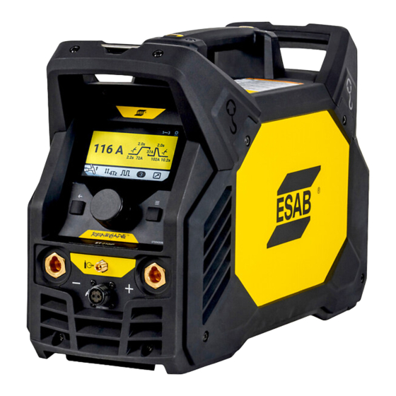
Renegade ET 210iP Advanced is an inverter-based power source intended for MMA (Manual Metal Arc), TIG (Tungsten Inert Gas) and HF TIG (High Frequency Tungsten Inert Gas) welding. ESAB accessories for the product can be found in the "ACCESSORIES" chapter of this manual. Equipment Renegade ET 210iP Advanced includes:... -
Page 10: Technical Data
Constant sound pressure when idling <70 db Dimensions l × w × h 460 × 200 × 320 mm (18.1×7.9×12.6 in.) Weight 11 kg (24.3 lbs) Insulation class Enclosure class IP 23 Application class 0463 859 001 - 10 - © ESAB AB 2023... - Page 11 Equipment marked IP23 is intended for indoor and outdoor use. Application class The symbol indicates that the power source is designed for use in areas with increased electrical hazard. 0463 859 001 - 11 - © ESAB AB 2023...
-
Page 12: Eco Design Information
3B. Revision level (last digit of year and week number) 3C. Year & week produced (last two digits of year and week number) 3D. Sequential number system (each week starts with 0001) 0463 859 001 - 12 - © ESAB AB 2023... -
Page 13: Installation
Position the power source so that cooling air inlets and outlets are not obstructed. A. Minimum 200 mm (8 in.) B. Minimum 200 mm (8 in.) WARNING! Secure the equipment - particularly if the ground is uneven or sloping. 0463 859 001 - 13 - © ESAB AB 2023... -
Page 14: Lifting Instructions
S scmin 1. Rating plate with supply connection data. 0463 859 001 - 14 - © ESAB AB 2023... - Page 15 Automatic Voltage Regulation (AVR) or with equivalent or better type of regulation, with rated power of 7 kW are recommended. WARNING! If used under 115 VAC input supply, the supply plug rating must be higher than 20 A. 0463 859 001 - 15 - © ESAB AB 2023...
-
Page 16: Operation
8. Menu button adjusments 3. Back button 9. Power switch 4. Negative output (-) 10. Remote/torch control connection 5. Gas outlet 11. Cooler connection 6. Torch connection 12. Shield gas inlet 0463 859 001 - 16 - © ESAB AB 2023... -
Page 17: Connecting Welding And Return Cables
NOTE! Power supply of the cooling unit is done from the welding power source via the connection cable (for more information, refer to the cooling unit instruction manual). 0463 859 001 - 17 - © ESAB AB 2023... -
Page 18: Fan Control
Press and hold for 3s to delete jobs (on Jobs screen) 2. Menu navigation: turn and push to select or change values 3. Right button switch (Menu button) Press Menu button to direct return to menu screen 0463 859 001 - 18 - © ESAB AB 2023... -
Page 19: Information Screen
QR code. 1. Information Settings screen Press Menu button to enter Menu screen. Turn main knob to Settings icon and press main knob to enter settings menu screen. 1. Settings screen 0463 859 001 - 19 - © ESAB AB 2023... - Page 20 User can turn ON or OFF trigger job shift function by pressing main knob when this item is highlighted. 6. Cooler ON/OFF (Only TIG) 7. Reset setting 8. About (software version) 0463 859 001 - 20 - © ESAB AB 2023...
-
Page 21: Remote Screen
To remove a job, rotate main knob to scroll to the job position, press and hold Back Button until the screen displays “Clear this Job position”, confirm by pressing main knob. 0463 859 001 - 21 - © ESAB AB 2023... -
Page 22: Welding Screen
For MMA welding the power source shall be supplemented with: • welding cable with electrode holder • return cable with clamp 5.12.1 MMA/Stick Home screen 0463 859 001 - 22 - © ESAB AB 2023... -
Page 23: 5.12.2 Mma/Stick Menu Screen
When VRD is ON “VRD” is displayed in status bar of home screen. Factory default is VRD OFF (except for Australia). Contact an authorized ESAB service technician to activate this function. 2. Preset welding current: rotate main knob clockwise to increase preset welding current or anti-clockwise to decrease preset welding current. -
Page 24: Tig Welding
The HF (High Frequency) start function strikes the arc by means of a spark from the tungsten electrode to the workpiece as the electrode is brought closer to the workpiece and the trigger on the TIG torch is pressed. 0463 859 001 - 24 - © ESAB AB 2023... -
Page 25: 5.13.1 Tig Home Screen
See detailed introduction in XXX. Sequencer/Pulse TIG home view 1. Peak time view 3. Background current view 2. Frequency view 0463 859 001 - 25 - © ESAB AB 2023... -
Page 26: 5.13.2 Tig Menu Screen
Press main knob again to confirm value and exit adjustment mode. 0463 859 001 - 26 - © ESAB AB 2023... - Page 27 Setting range is 0.01-999 Hz. Increment value at each rotation of main knob changes as listed below. Factory default setting is 100 Hz. 0.01-0.99: 0.01 1.0-9.9: 0.1 10-100: 1 100-300: 10 300-999: 100 0463 859 001 - 27 - © ESAB AB 2023...
- Page 28 4. Peak time setting (push main knob and rotate to adjust) 5. Background current setting (push main knob and rotate to adjust) 6. Average current (read only) 4. Trigger mode 0463 859 001 - 28 - © ESAB AB 2023...
- Page 29 One quick tap on trigger (push and release) will switch the output weld current from "Main current" to "Secondary Current"; another quick tap on trigger will switch the current from "Secondary Current" to "Main Current". See below picture. 0463 859 001 - 29 - © ESAB AB 2023...
- Page 30 B = Slope up C = Slope down D = Gas post flow E = Secondary current Below illustration shows the navigation or setup of 4T2 Pulse in the Pulse screen. 0463 859 001 - 30 - © ESAB AB 2023...
- Page 31 9. Final current setting 4. Start current setting 10. Post-flow gas setting 5. Slop up setting 11. Current setting and review 6. Main current setting (Current A) 12. Welding screen 0463 859 001 - 31 - © ESAB AB 2023...
-
Page 32: Foot Pedal Functions Explanation
E = Set current B = Slope up F = Remote min current C = Slope down G = Current range adjustable by the foot pedal D = Gas post flow 0463 859 001 - 32 - © ESAB AB 2023... - Page 33 E = Set current B = Slope up F = Remote min current C = Slope down G = Current range adjustable by the foot pedal D = Gas post flow 0463 859 001 - 33 - © ESAB AB 2023...
-
Page 34: Maintenance
Area to maintain Every 3 months Clean or replace Clean weld terminals. Check or replace weld unreadable labels. cables. Every 6 months Clean inside equipment. Use dry compressed air with 4 bar pressure. 0463 859 001 - 34 - © ESAB AB 2023... -
Page 35: Cleaning Instruction
Since the power source contains one "dirty side" (the right side) and one "clean side" (the left side), it is important that you do not remove the left side panel before cleaning the right side of the power source. 0463 859 001 - 35 - © ESAB AB 2023... - Page 36 5. Clean the left side of the power source, using dry compressed air with reduced pressure. 6. Make sure that there is no dust left on any part of the power source. 0463 859 001 - 36 - © ESAB AB 2023...
- Page 37 90° into the power source, so that it is positioned between the welding outlet connector and the transformer outlets. 8. Tighten the screws on the side panels with 3 Nm ± 0.3 Nm (26.6 in lb. ± 2.6). 0463 859 001 - 37 - © ESAB AB 2023...
-
Page 38: Troubleshooting
Make sure the recommended duty cycle for the weld current has not frequently been exceeded. See section "Duty cycle" in the TECHNICHAL DATA chapter. Make sure the air inlets or outlets are not clogged. Clean inside machine according to routine maintenance. 0463 859 001 - 38 - © ESAB AB 2023... -
Page 39: Calibration And Valiation
1 A. The measuring range is specified by the rating plate on the used Renegade ET 210i Advanced welding power source. Recommended method and applicable standard ESAB recommend calibration and validation to be executed according to IEC/EN 60974-14(:2018) or EN 50504:2008 (unless another way of execution is communicated from ESAB). 0463 859 001 - 39 - ©... -
Page 40: Error Codes
If several errors have been detected only the code for the last occurring error is displayed. Error code descriptions Error codes that the user can handle are listed below. If any other error code appears, contact an authorised ESAB service technician. Error code Description... -
Page 41: Ordering Spare Parts
Spare parts and wear parts can be ordered through your nearest ESAB dealer, see esab.com. When ordering, please state product type, serial number, designation and spare part number in accordance with the spare parts list. -
Page 42: Wiring Diagram
APPENDIX APPENDIX WIRING DIAGRAM 0463 859 001 - 42 - © ESAB AB 2023... -
Page 43: Ordering Numbers
* here. Make sure to use a manual with a serial number or software version that corresponds with the product, see the front page of the manual. Technical documentation is available on the Internet at: www.esab.com 0463 859 001 - 43 - © ESAB AB 2023... -
Page 44: Accessories
Electrode holder Handy, 200 A with 25 mm , 3 m, OKC 50 0700 500 084 Remote control, MMA 4 W4014450 Foot pedal with 4.5 m (15 ft) cable, 8 PIN 0445 197 880 Shoulder strap 0463 859 001 - 44 - © ESAB AB 2023... - Page 45 APPENDIX 0460 330 881 Trolley 0465 720 002 ESAB coolant 0463 859 001 - 45 - © ESAB AB 2023...
- Page 46 For contact information visit http://esab.com ESAB AB, Lindholmsallén 9, Box 8004, 402 77 Gothenburg, Sweden, Phone +46 (0) 31 50 90 00 manuals.esab.com...
Need help?
Do you have a question about the ET 210iP Advanced and is the answer not in the manual?
Questions and answers