
Subscribe to Our Youtube Channel
Related Manuals for ESAB ET 201i DC


Summary of Contents for ESAB ET 201i DC
- Page 1 ET 201i DC Inverter Arc Welder Operating Manual English Canadien Français Art # A-13034 3163339 Revision: AA Issue Date: Manual No.: March 30, 2016 0-5452 esab.com...
- Page 2 WE APPRECIATE YOUR BUSINESS! Congratulations on your new ESAB product. We are proud to have you as our customer and will strive to provide you with the best service and reliability in the industry. This product is backed by our extensive warranty and world-wide service network. To locate your nearest distributor or service agency, visit us on the web at www.esab.com...
- Page 3 Welding Power Supply Operating Manual Number 0-5452 for: ESAB ET 201i DC Power Source Arc Welder Part No. W1003806 ESAB ET 201i DC System with Stick/TIG Kit & Case Part No. W1003807 Published by: ESAB Group Inc. 2800 Airport Rd.
- Page 4 Be sure this information reaches the operator. You can get extra copies through your supplier. CAUTION These INSTRUCTIONS are for experienced operators. If you are not fully familiar with the principles of operation and safe practices for arc welding and cutting equipment, we urge you to read our booklet, “Precautions and Safe Practices for Arc Welding, Cut- ting, and Gouging,”...
- Page 5 ASSUREZ-VOUS QUE CETTE INFORMATION EST DISTRIBUÉE À L’OPÉRATEUR. VOUS POUVEZ OBTENIR DES COPIES SUPPLÉMENTAIRES CHEZ VOTRE FOURNISSEUR. ATTENTION Les INSTRUCTIONS suivantes sont destinées aux opérateurs qualifiés seulement. Si vous n’avez pas une connaissance approfondie des principes de fonctionnement et des règles de sécurité pour le soudage à l’arc et l’équipement de coupage, nous vous suggérons de lire notre brochure «...
-
Page 6: Table Of Contents
TABLE OF CONTENTS SECTION 1: SAFETY ..................1-1 Safety Precautions ..................1-1 SECTION 2: INTRODUCTION ..................2-1 2.01 How to Use This Manual ................. 2-1 2.02 Equipment Identification ................. 2-1 2.03 Receipt of Equipment ..................2-1 2.04 Description ..................... 2-1 2.05 Transportation Methods .................. - Page 7 TABLE OF CONTENTS 4.18 Arc Length ...................... 4-9 4.19 Rate of Travel ....................4-9 4.20 Making Welded Joints ................... 4-10 4.21 Distortion ...................... 4-12 4.22 The Cause of Distortion ................4-12 4.23 Overcoming Distortion Effects ..............4-12 SECTION 5: SERVICE ....................5-1 5.01 Maintenance and Inspection ................
- Page 8 TABLE OF CONTENTS This Page Intentionally Blank...
-
Page 9: Section 1: Safety
SECTION 1: SAFETY Safety Precautions Users of ESAB welding and plasma cutting equipment have the ultimate responsibility for ensuring that anyone who works on or near the equipment observes all the relevant safety precautions. Safety precautions must meet the requirements that apply to this type of welding or plasma cutting equipment. The following recommendations should be observed in addition to the standard regulations that apply to the workplace. - Page 10 ET 201i DC Arc welding and cutting can be injurious to yourself and others. Take WARNING precautions when welding and cutting. Ask for your employer's safety practices which should be based on manufacturers' hazard data. ELECTRIC SHOCK - Can kill.
-
Page 11: Introduction
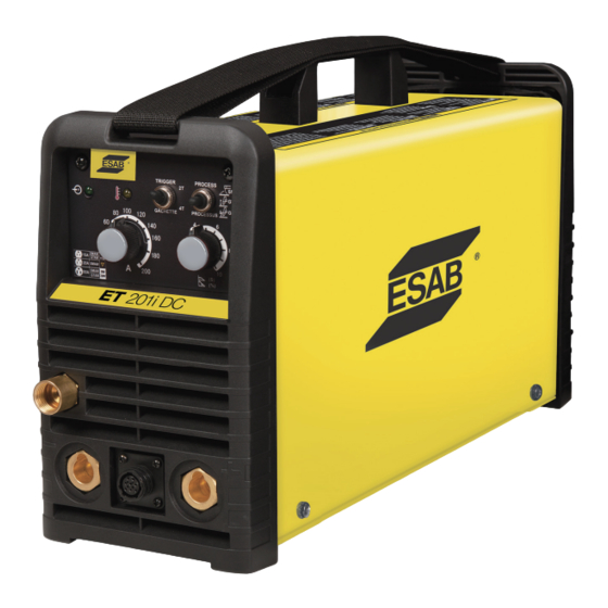
2.04 Description helpful in efficient operation of the system. The ET 201i DC is a compact inverter welding machine that WARNING has infinitely adjustable welding current from 10 to 200 A procedure which, if not properly followed, may amps. -
Page 12: Duty Cycle
ET 201i DC 2.06 Duty Cycle The rated duty cycle of a Welding Power Source, is the percentage of a ten minute time period that it may be operated at its rated output current without exceeding the temperature limits of the insulation of the component parts. To explain the 10 minute duty cycle period, suppose a Welding Power Source is designed to operate with a 30% duty cycle at 160 amperes and 26.4 volts. - Page 13 (Based on Article 630, National Electrical Code). ESAB continuously strives to produce the best product possible and therefore reserves the right to change, improve or revise the specifications or design of this or any product without prior notice. Such updates or changes do not entitle the buyer of equip- ment previously sold or shipped to the corresponding changes, updates, improvements or replacement of such items.
- Page 14 ET 201i DC This Page Intentionally Blank INTRODUCTION 0-5452...
-
Page 15: Installation
• In areas, not exposed to direct sunlight or rain. • Place at a distance of 12” (300mm) or more from walls or similar that could restrict natural air flow for cooling. WARNING ESAB advises that this equipment be electrically connected by a qualified electrician. 0-5452 INSTALLATION... -
Page 16: Electrical Input Connections
ET 201i DC 3.03 Electrical Input Connections WARNING ELECTRIC SHOCK can kill; SIGNIFICANT DC VOLTAGE is present after removal of input power. DO NOT TOUCH live electrical parts. SHUT DOWN welding power source, disconnect input power employing lockout/tagging procedures. Lock-out/tagging procedures consist of padlocking line disconnect switch in open position, removing fuses from fuse box, or shutting off and red-tagging circuit breaker or other disconnecting device. - Page 17 ET 201i DC 208-230V, 50A, 1Ø Welding Power Supply 20A, 1Ø The Adapters enable connection to all these power outlets 15A, 1Ø Primary Power Cable Art# A-09789 Figure 3-1: Electrical Input Connections Input Power Each unit incorporates an INRUSH circuit. When the MAIN CIRCUIT SWITCH is turned on, the inrush circuit provides pre-charging for the input capacitors.
-
Page 18: Electromagnetic Compatibility
ET 201i DC C. Methods of Reducing Electromagnetic Emissions 3.04 Electromagnetic Compatibility 1. Mains Supply WARNING Extra precautions for Electromagnetic Compatibility Welding equipment should be connected to the may be required when this Welding Power Source is mains supply according to the manufacturer’s used in a domestic situation. - Page 19 ET 201i DC 5. Earthing of the Work Piece Where the work piece is not bonded to earth for electrical safety, nor connected to earth because of its size and position, e.g. ship’s hull or building steelwork, a connection bonding the work piece to earth may reduce emissions in some, but not all instances.
-
Page 20: Setup For Welding
ET 201i DC 3.05 Setup for Welding NOTE! Conventional operating procedures apply when using the Welding Power Source, i.e. connect work lead directly to work piece and electrode lead is used to hold electrode. Wide safety margins provided by the design ensure that the Welding Power Source will withstand short-term overload without adverse effects. - Page 21 ET 201i DC STICK (SMAW) Mode Sequence of Operation CAUTION Before any welding is to begin, be sure to wear all appropriate and recommended safety equipment. 1. Switch the ON/OFF Switch (located on the rear panel) to OFF. 2. Connect the ground (work) clamp cable to the negative output terminal, and the electrode holder cable to the positive output terminal.
-
Page 22: Victor Regulator
ET 201i DC 3.07 Victor Regulator WARNING use a regulator that delivers pressure DO NOT Pressure regulator (Figure 3-3) attached to the cylinder exceeding the pressure rating of the downstream valve reduce high cylinder pressures to suitable low equipment unless pro visions are made to prevent working pressures for welding, cutting, and other over-pressurization (i.e. -
Page 23: Leak Testing The System
ET 201i DC 3.08 Leak Testing the System WARNING Stand to the side of the cylinder opposite the Leak test the system before putting into operation. regulator when opening the cylinder valve. Keep 1. Be sure that there is a valve in the downstream the cylinder valve between you and the regulator. -
Page 24: Lift Tig (Gtaw) Setup
ET 201i DC 3.09 LIFT TIG (GTAW) Setup Set Process Selection Switch to LIFT TIG. Switch to 2T/4T Set Welding Current as specified by the Set DOWN Slope Electrode Manufacturer. Secure the gas cylinder in an Positive Output upright position by chaining it... - Page 25 ET 201i DC LIFT TIG (GTAW) Sequence of Operation CAUTION Before any welding is to begin, be sure to wear all appropriate and recommended safety equipment. 1. Switch the ON/OFF Switch (located on the rear panel) to OFF. 2. Connect the ground (work) clamp cable to positive output terminal. It is essential that the male plug is inserted and turned fully clockwise until connector locks in place to achieve reliable electrical connection.
-
Page 26: Hf Tig (Gtaw) Setup
Terminal Negative to a stationary support to prevent (Dinse™ 50) Output falling or tipping. Terminal (Dinse™ 50) Art # A-10100_AB Figure 3-7: Setup for HF TIG (GTAW) Welding of ET 201i DC INSTALLATION 0-5452 3-12... - Page 27 ET 201i DC HF TIG (GTAW) Sequence of Operation CAUTION Before any welding is to begin, be sure to wear all appropriate and recommended safety equipment. 1. Switch the ON/OFF Switch (located on the rear panel) to OFF. 2. Connect the ground (work) clamp cable to positive output terminal. It is essential that the male plug is inserted and turned fully clockwise until connector locks in place to achieve reliable electrical connection.
-
Page 28: When You Finish Using The Regulator
ET 201i DC 3.11 When You Finish Using the Regulator 1. Close the cylinder valve. 2. Open the valve on the downstream equipment. This drains all pressure from the system. 3. Close the valve on the downstream equipment. 4. Turn the adjusting screw counterclockwise to release the ten sion on the adjusting spring. -
Page 29: Operation
SMAW STICK 32A OUTLET 32A OUTLET 110V SMAW 208/ TIG/STICK 16A OUTLET 230V GTAW 230V (I) 8 Pin Control Socket (G) Gas Outlet Positive Output Terminal Negative Output Terminal Art # A-13035 Figure 4-1: ET 201i DC Controls 0-5452 OPERATION... - Page 30 ET 201i DC A. POWER Indicator The POWER Indicator illuminates when the ON/OFF switch is in the ON position and the correct mains voltage is present. B. FAULT Indicator If Fault indicator lights up continuously then that is an Overcurrent Condition and needs to be serviced by an Autho- rized ESAB Technician.
-
Page 31: Welding Current Control Explanation
ET 201i DC 4.03 Welding Current Control I. 8 Pin Remote Socket The 8 pin remote socket is used to connect the TIG Torch Explanation Trigger Switch to the welding Power Source. To make con- 15 Amp Outlet nections, align keyway, insert plug, and rotate threaded collar fully clockwise. -
Page 32: Stick (Smaw) Electrode Polarity
ET 201i DC Output Scale for 208/230V The outside number scale identifies the available output weld current for STICK or LIFT TIG/HF TIG weld modes. Nuisance tripping should not occur on a 50A 208/230V outlet for both STICK & LIFT TIG/HF TIG Modes. -
Page 33: Gtaw Electrode Polarity
ET 201i DC eral work. These include some low hydrogen types for high tensile steel, cellulose types for welding large diameter pipes, etc The range of electrodes dealt with in this publication will cover the vast majority of applications likely to be encountered;... -
Page 34: Tungsten Electrode Types
ET 201i DC 4.10 Tungsten Electrode Types Electrode Type Welding Application Features Color Code (Ground Finish) DC welding of mild steel, stainless steel Excellent arc starting, long life, high Thoriated 2% and copper. current carrying capacity. AC & DC welding of mild steel, stainless... - Page 35 ET 201i DC Art # A-07687 Art A-07691 Figure 4-3: Flat position, down hand butt weld Figure 4-7: Vertical position, butt weld Art # A-07692 Art # A-07688 Figure 4-4: Flat position, gravity fillet weld Figure 4-8: Vertical position, fillet weld...
-
Page 36: Joint Preparations
ET 201i DC 4.14 Joint Preparations In many cases, it will be possible to weld steel sections without any special preparation. For heavier sections and for repair work on castings, etc., it will be necessary to cut or grind an angle between the pieces being joined to ensure proper penetration of the weld metal and to produce sound joints. -
Page 37: Arc Welding Technique
ET 201i DC 4.15 Arc Welding Technique Another difficulty you may meet is the tendency, after the arc is struck, to withdraw the electrode so far that the arc A Word to Beginners is broken again. A little practice will soon remedy both of these faults. -
Page 38: Making Welded Joints
ET 201i DC 4.20 Making Welded Joints 4-14. The width of weave should not be more than three times the core wire diameter of the electrode. When the Having attained some skill in the handling of an electrode, joint is completely filled, the back is either machined, you will be ready to go on to make up welded joints. - Page 39 ET 201i DC C. Vertical Welds 1. Vertical Up Tack weld a three feet length of angle iron to your work bench in an upright position. Use a 1/8" (3.2mm) E7014 electrode and set the current at 120 amps. Make yourself comfortable on a seat...
-
Page 40: Distortion
ET 201i DC The metal in the weld area is stretched (plastic deforma- 4.21 Distortion tion), the job may be pulled out of shape by the powerful Distortion in some degree is present in all forms of contraction stresses (distortion), or the weld may crack, in welding. - Page 41 ET 201i DC D. Presetting It is possible in some cases to tell from past experience or to find by trial and error (or less frequently, to calculate) how much distortion will take place in a given welded structure. By correct pre-setting of the components to be Art # A-07710_AB Block Sequence.
- Page 42 ET 201i DC This Page Intentionally Blank OPERATION 0-5452 4-14...
-
Page 43: Service
ET 201i DC SECTION 5: SERVICE 5.01 Maintenance and Inspection To clean the unit, open the enclosure and use a vacuum cleaner to remove any accumulated dirt and dust. The unit The only routine maintenance required for the power should also be wiped clean, if necessary; with solvents supply is a thorough cleaning and inspection, with the that are recommended for cleaning electrical apparatus. -
Page 44: Stick (Smaw) Welding Problems
ET 201i DC 5.02 STICK (SMAW) Welding Problems Description Possible Cause Remedy 1. Gas pockets or voids in weld metal Electrodes are damp. A. Dry electrodes before use. (Porosity). B. Reduce welding current. Welding current is too high. Surface impurities such as oil, C. -
Page 45: Tig Welding Problems
ET 201i DC 5.03 TIG Welding Problems Weld quality is dependent on the selection of the correct consumables, maintenance of equipment and proper welding technique. Description Possible Cause Remedy 1. Excessive bead build-up or poor Welding current is too low... -
Page 46: Power Source Problems
There are extremely dangerous voltages and power levels present inside this product. Do not attempt to repair unless you are an Accredited ESAB Service Agent and you have had training in power measurements and troubleshooting techniques. If major complex subassemblies are faulty, then the Welding Power Source must be returned to an Accredited ESAB Service Agent for repair. -
Page 47: Key Spare Parts
There are extremely dangerous voltages and power levels present inside this product. Do not attempt to repair unless you are an Accredited ESAB Service Agent and you have had training in power measurements and troubleshooting techniques. If major complex subassemblies are faulty, then the Welding Power Source must be returned to an Accredited ESAB Service Agent for repair. - Page 48 ET 201i DC Art # A-10104_AC KEY SPARE PARTS 0-5452...
-
Page 49: Appendix 1: Options And Accessories
ET 201i DC APPENDIX 1: OPTIONS AND ACCESSORIES Description Part Number 17 style TIG Torch with 12.5ft lead, finger remote control, 50mm dinse connection and W4012701 accessory kit with 1/16", 3/32", 1/8" thoriated tungstens; 1/16", 3/32", 1/8" collets; 1/16", 3/32", 1/8"... -
Page 50: Appendix 2: System Schematic
ET 201i DC APPENDIX 2: SYSTEM SCHEMATIC 2 CURRENT DEMAND PANEL CUR.DEMAND 3 WHITE YELLOW GRAY BLACK BLACK COMMON 4 CURRENT FEEDBACK 3 -15VDC 2 +15VDC 1 +24VDC 1 RTN 2 3 -24VDC 2 COMMON 1 +24VDC COMMON 7 OVER CURRENT 6... - Page 51 This Page Intentionally Blank...
- Page 52 SOUTH AFRICA Bucharest Vamberk Tel: +40 316 900 600 ESAB Mexico S.A. ESAB Africa Welding & Cutting Ltd Tel: +420 2 819 40 885 Fax: +40 316 900 601 Monterrey Durbanvill 7570 - Cape Town Fax: +420 2 819 40 120...
Need help?
Do you have a question about the ET 201i DC and is the answer not in the manual?
Questions and answers