
Related Manuals for Impulse SL7046


Summary of Contents for Impulse SL7046
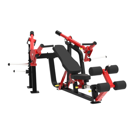
- Page 1 SL7046 ISO-Lateral Super Chest Press Owner's Manual CAUTION! Read all precautions and instructions in this manual before using this equipment.
-
Page 2: Table Of Contents
Table Of Contents CAUTION! Read all precautions and instructions in this manual before using this equipment. Important Safety Instructions----------------------------------------------------------- 3 Instructions-------------------------------------------------------------------------------- 5 Exploded View and Parts List------------------------------------------------------------ 6 Measurement Guide--------------------------------------------------------------------- 20 Assembly Instructions------------------------------------------------------------------ 21 Assembly--------------------------------------------------------------------------------- 22 Adjust Instructions and Exercise Instructions---------------------------------------- 27 Maintenance Schedule------------------------------------------------------------------ 29 General Maintenance Information----------------------------------------------------- 30 Weight Training Tips-------------------------------------------------------------------- 31... -
Page 3: Important Safety Instructions
Important Safety Instructions Before beginning any fitness program, you should obtain a complete physical examination from your physician. When using exercise equipment, basic precautions should always be taken, including the following: 1. Read all instructions before using the equipment. These instructions are written to ensure your safety and to protect the unit. 2. - Page 4 Important Safety Instructions Personal Safety During Assembly Read each step in the assembly instructions and follow the steps in sequence. Do not skip ahead. If you skip ahead, you may learn later that you have to disassemble components and that you may have damaged the equipment. Assemble and operate the equipment on a solid, level surface.
-
Page 5: Instructions
Instructions Before beginning assembly please take the time to read instructions thoroughly. Please use the various lists in this manual to make sure that all parts have been included in your shipment. When ordering, use part number and description from the lists. -
Page 6: Exploded View And Parts List
Exploded View and Parts List Overall Grade No. Part No. Description Item No. SL704601ASSY Left Frame ASSY SL704602ASSY Right Frame ASSY SL70460300 Rear Crossmember SL704604ASSY Main Frame ASSY ABS701307ASSY Foam Tube ASSY SL703910ASSY Weight Horn ASSY SL703911ASSY Weight Plate Storage ASSY SL704608ASSY Left Arm Frame ASSY SL704609ASSY... - Page 7 Exploded View and Parts List Overall...
- Page 8 Exploded View and Parts List Left Frame ASSY Grade No. Part No. Description Item No. SL70460100 Left Frame CWRVL0051200V1 Rubber Foot PL380800 Large Rubber Bumper PS10007100 Bumper PNLM6*15DHS20 Button Head Cap Screw M16*15 GB70M12*90DHS20 Socket Head Cap Screw M12*120 GB9512DHS2 Flat Washer Φ13*Φ24*1.5 NM12DHS2 Nylon Lock Nut M12...
- Page 9 Exploded View and Parts List Right Frame ASSY Grade No. Part No. Description Item No. SL70460200 Right Frame CWRVL0051200V1 Rubber Foot PL380800 Large Rubber Bumper PS10007100 Bumper PNLM6*15DHS20 Button Head Cap Screw M16*15 GB70M12*90DHS20 Socket Head Cap Screw M12*120 GB9512DHS2 Flat Washer Φ13*Φ24*1.5 NM12DHS2 Nylon Lock Nut M12...
- Page 10 Exploded View and Parts List Main Frame Sub ASSY Swinging Support Frame ASSY Grade No. Part No. Description Item No. 4.1.1 SL70460400 Main Frame Pipe Plug □50*100 4.1.2 VLP8000 4.1.3 BS81223100 Rubber Foot 4.1.4 IT95021600 Spring Pin 4.1.5 RS17000400 Bumper 4.1.6 GB70M10*20DHS20NL Socket Head Cap Screw M10*20...
- Page 11 Exploded View and Parts List Sliding Rack ASSY Support Frame ASSY Grade No. Part No. Description Item No. 4.5.1 SL70460500 Sliding Rack Tube Guide □63.5*□50.8 4.5.2 KPSOB2100V1 4.5.3 VLP8000 Pipe Plug□50*100 4.5.4 M02502000 Bushing Φ38*Φ32*Φ25.4*18 4.5.5 IT95251600 Spring Pin Grade No. Part No. Description Item No.
- Page 12 Exploded View and Parts List Main Frame ASSY Grade No. Part No. Description Item No. SL70460400ASSY Main Frame Sub ASSY SL70461200ASSY Swinging Support Frame ASSY SL70412500 Spring PBF9001803 Ball SL704605ASSY Sliding Rack ASSY SL70460600 Back Pad Frame SL704107ASSY Support Frame ASSY SL70461500 Adjustable Tube IF93272100...
- Page 13 Exploded View and Parts List Main Frame ASSY...
- Page 14 Exploded View and Parts List Foam Tube ASSY Weight Horn ASSY Weight Plate Storage ASSY Grade No. Part No. Description Item No. ABS70130700 Foam Tube IF81165000 Nut Φ25 Grade No. Part No. Description Item No. SL70391000 Weight Horn HSP70522000 Long Weight Horn Sleeve SL70012000 Weight Horn Plastic Cap GB70M12*30DS20NL...
- Page 15 Exploded View and Parts List Left Arm Frame Sub ASSY Left Arm Frame ASSY Grade No. Part No. Description Item No. 8.1.1 SL70460800 Left Arm Frame 8.1.2 HF42641300 Pipe Plug Φ76 8.1.3 GB2766206-2ZC3 Deep Groove Ball Bearing Φ30*Φ62*16 8.1.4 M02502000 Bushing Φ38*Φ32*Φ25.4*18 Grade No.
- Page 16 Exploded View and Parts List Right Arm Frame Sub ASSY Right Arm Frame ASSY Grade No. Part No. Description Item No. 9.1.1 SL70460900 Right Arm Frame 9.1.2 HF42641300 Pipe Plug Φ76 9.1.3 GB2766206-2ZC3 Deep Groove Ball Bearing Φ30*Φ62*16 9.1.4 M02502000 Bushing Φ38*Φ32*Φ25.4*18 Grade No.
- Page 17 Exploded View and Parts List Left Handle Frame ASSY Grade No. Part No. Description Item No. 10.1 SL70461000 Left Handle Frame 10.2 IF81212700 Nut Φ32 10.3 HF42641300 Pipe Plug Φ76 10.4 SL70461900 Left Lining Plate 10.5 IT90122100 Aluminium Grip Ring Φ32 10.6 IT90122000 Aluminium Grip Cap Φ32...
- Page 18 Exploded View and Parts List Right Handle Frame ASSY Grade No. Part No. Description Item No. 11.1 SL70461100 Right Handle Frame 11.2 IF81212700 Nut Φ32 11.3 HF42641300 Pipe Plug Φ76 11.4 SL70462000 Right Lining Plate 11.5 IT90122100 Aluminium Grip Ring Φ32 11.6 IT90122000 Aluminium Grip Cap Φ32...
- Page 19 Exploded View and Parts List Swing Frame ASSY Grade No. Part No. Description Item No. 13.1 SL70461300 Swing Frame 13.2 IF81165000 Nut Φ25 13.3 M02502000 Bushing Φ38*Φ32*Φ25.4*18 13.4 IT90102200 Aluminium Grip Ring Φ25 13.5 IT90102100 Aluminium Grip Cap Φ25 13.6 026-01PL0206-12 Φ25 Grip 13.7...
-
Page 20: Measurement Guide
Measurement Guide BHCS = Button Head Cap Screw SHCS = Socket Head Cap Screw FHCS = Flat Head Cap Screw HHB = Hex Head Bolt Millimeters Inches Diameter of bolt M6(1/4") M8(5/16") M10(3/8") M12(1/2") M16(5/8") (mm/inch) Tightening 9~12 22~30 45~59 78~104 193~257 torque (N.m) -
Page 21: Assembly Instructions
Assembly Instructions Assembly of the equipment takes professional installers about 2 hours. If this is the first time you have assembled this type of equipment, plan to spend more time. It is strongly recommended to assemble the equipment by professional installers. You may find it quicker, safer, easier to assemble this equipment with the help of a friend, as some of components may be large, heavy or awkward to handle alone. -
Page 22: Assembly
Assembly STEP 1 Attach the Left Frame ASSY (#1) and the Right Frame ASSY (#2) with the Rear Crossmember (#3) and the Main Frame ASSY (#4) using: two M12*125 SHCS (#25) four M12*105 SHCS (#26) twelve Φ13*Φ24*2.5 Flat Washer (#36) six M12 Nylon Lock Nut (#39) Note: Hand tighten bolts and Nylon Lock Nuts until machine is fully assembled. - Page 23 Assembly STEP 2 1. Attach the Left Arm Frame ASSY (#8) and the Right Arm Frame ASSY (#9) to the Left Frame ASSY (#1) and the Right Frame ASSY (#2) using: two Pivot Shaft Φ30 (#14) four Φ54*Φ12.5*10.6 Aluminum End Cap (#19) four M12*30 FHCS (#32) 2.
- Page 24 Assembly STEP 3 1. Attach two Weight Plate Storage ASSY (#7) to the Left Frame ASSY (#1) and the Right Frame ASSY (#2) using: four M12*105 SHCS (#26) eight Φ13*Φ24*2.5 Flat Washer (#36) four M12 Nylon Lock Nut (#39) 2. Attach two Weight Horn ASSY (#6) to the Left Arm Frame ASSY (#8) and the Right Arm Frame ASSY (#9) using: two Weight Horn Rubber Donut (#18) two Φ54*Φ12.5*10.6 Aluminum End Cap (#19)
- Page 25 Assembly STEP 4 1. Attach the Swing Frame ASSY (#13) to the Main Frame ASSY (#4) using: one Pivot Shaft Φ25.4 (#12) two Φ38*Φ10.5*8 Aluminum End Cap (#20) two M10*30 FHCS (#33) one M8*25 SHCS (#30) one Sleeve Φ17*10.5 (#23) one Φ9*Φ16*1.6 Flat Washer (#38) one M8 Nylon Lock Nut (#40) 2.
- Page 26 Assembly STEP 5 1. Attach four Foam Pad (#15) to two Foam Tube ASSY (#5) and the Swing Frame ASSY (#13) using: four Cap ASSY (#21) four Φ60*Φ26*12 Plastic Ring (#22) four M10*35 SHCS (#28) two Socket Set Screw M8*10 (#34) 2.
-
Page 27: Adjust Instructions And Exercise Instructions
Adjust Instructions and Exercise Instructions Weight Plate Installation Requirements 1. Please use Olympic Weight Plate which hole is greater than Φ50mm and external diameter is less than Φ450mm. 2. The total weight can not be greater than 150kg. 3. This equipment does not contains Weight Plate. Desired position adjustment 1. - Page 28 Adjust Instructions and Exercise Instructions Exercise Instructions 1. Select an appropriate weight. 2. Adjust the spring pin to the desired position (Decline\ Flat\ Incline). 3. Sit with back against back pad and seat in desired position. 4. Press handles straight upward. 5.
-
Page 29: Maintenance Schedule
Maintenance Schedule COMMERCIAL HOME LATEST DATE ENTRY ROUTINE MAINTENANCE MAINTENANCE Inspect; Links, Pull Pins, Snap Locks, DAILY WEEKLY Swivels, Weight Stack Pins Clean; DAILY WEEKLY Upholstery Inspect; DAILY WEEKLY Cables or Belts and their tension Inspect; WEEKLY 3 MONTHS Accessory Bars, and Handles Inspect;... -
Page 30: General Maintenance Information
General Maintenance Information Links, Pull-Pins, Snap Hooks, Swivels, Weight Stack Pins: * Check all pieces for signs of visible wear or damage. * Check springs in snap hooks and pull-pins for proper tension and alignment. * If the spring sticks or has lost its rigidity, replace it immediately. Upholstery: * To ensure prolonged upholstery life and proper hygiene, all upholstered pads should be wiped down with a damp cloth after every workout. -
Page 31: Weight Training Tips
Weight Training Tips Use this manual to guide you through the basic exercises you can perform on your equipment. To gain maximum results and avoid possible injury, consult a fitness professional to develop your complete exercise program. Always consult your physician before starting any exercise program. To be successful in your exercise program, it is important to develop an understanding of the basic principles of strength training.
Need help?
Do you have a question about the SL7046 and is the answer not in the manual?
Questions and answers