
Related Manuals for Impulse SL7040


Summary of Contents for Impulse SL7040
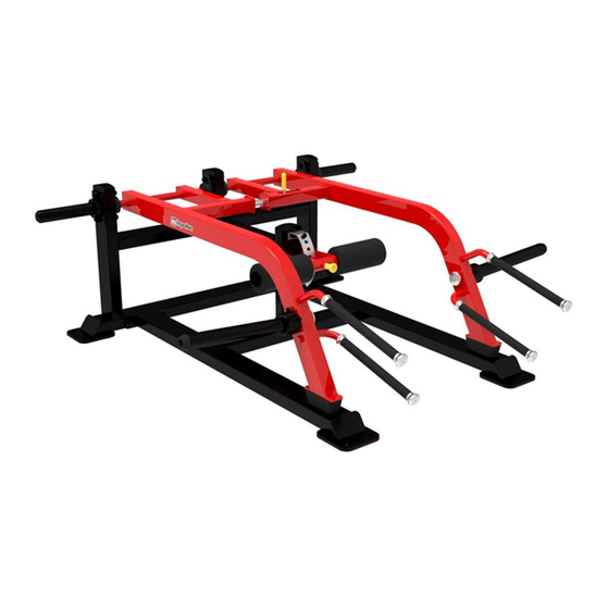
- Page 1 SL7040 Squat Lunge Owner's Manual CAUTION! Read all precautions and instructions in this manual before using this equipment.
-
Page 2: Table Of Contents
Table Of Contents CAUTION! Read all precautions and instructions in this manual before using this equipment. Important Safety Instructions----------------------------------------------------------- 3 Instructions-------------------------------------------------------------------------------- 5 Exploded View and Parts List------------------------------------------------------------ 6 Measurement Guide--------------------------------------------------------------------- 13 Assembly Instructions------------------------------------------------------------------ 14 Assembly--------------------------------------------------------------------------------- 15 Adjust Instructions and Exercise Instructions---------------------------------------- 23 Maintenance Schedule------------------------------------------------------------------ 24 General Maintenance Information----------------------------------------------------- 25 Weight Training Tips-------------------------------------------------------------------- 26... -
Page 3: Important Safety Instructions
Important Safety Instructions Before beginning any fitness program, you should obtain a complete physical examination from your physician. When using exercise equipment, basic precautions should always be taken, including the following: 1. Read all instructions before using the equipment. These instructions are written to ensure your safety and to protect the unit. 2. - Page 4 Important Safety Instructions Personal Safety During Assembly Read each step in the assembly instructions and follow the steps in sequence. Do not skip ahead. If you skip ahead, you may learn later that you have to disassemble components and that you may have damaged the equipment. Assemble and operate the equipment on a solid, level surface.
-
Page 5: Instructions
Instructions Before beginning assembly please take the time to read instructions thoroughly. Please use the various lists in this manual to make sure that all parts have been included in your shipment. When ordering, use part number and description from the lists. -
Page 6: Exploded View And Parts List
Exploded View and Parts List Overall Grade No. Part No. Description ItemNo. SL704001ASSY Base Frame ASSY SL704002ASSY Rear Support Frame ASSY SL704003ASSY Left Swing Frame ASSY SL704004ASSY Right Swing Frame ASSY SL704005ASSY Support Frame ASSY SL704006ASSY Swing Frame ASSY SL704007ASSY Weight Plate Storage ASSY SL704008ASSY Weight Horn Ass embly... - Page 7 Exploded View and Parts List Overall...
- Page 8 Exploded View and Parts List Base Frame ASSY Rear Support Frame ASSY Grade No. Part No. Description ItemNo. SL70400100 Base Frame CWRVL0051200 Rubber Foot Grade No. Part No. Description ItemNo. SL70400200 Rear Support Frame VLP8000 Pipe Plug CWRVL0051200 Rubber Foot...
- Page 9 Exploded View and Parts List Left Swing Frame ASSY Grade No. Part No. Description ItemNo. SL70400300 Left Swing Frame PL380800 Large Rubber Bumper End Cap □ 50.8*76.2 KPSFID2800 End Cap □ 50.8 KPSFID3000 IT95333000 Grip STΦ30*Φ22*325 IT90102100 Aluminium Grip Cap Φ25 IT90102200 Aluminium Grip Ring Φ25 GB9512DHS2...
- Page 10 Exploded View and Parts List Right Swing Frame ASSY Grade No. ItemNo. Part No. Description SL70400400 Right Swing Frame SL70402000 Axle SL70403000 Handle PL380800 Large Rubber Bumper End Cap □ 50.8*76.2 KPSFID2800 End Cap □ 50.8 KPSFID3000 IT95333000 Grip STΦ30*Φ22*325 IT90102100 Aluminium Grip Cap Φ25 IT90102200...
- Page 11 Exploded View and Parts List Support Frame ASSY Swing Frame ASSY Grade No. Part No. Description ItemNo. SL70400500 Support Frame HSP70512200ZH Arc-shaped Adjust Plate HVCORE5300 Bushing Φ19 VLP8000 Pipe Plug IN-S10111200 Little Bumper GB9510DHS2 Flat Washer Φ11*Φ20*2 GB958DHS2 Flat Washer Φ9*Φ16*1.6 NM10DHS2 Nylon Lock Nut M10 NM8DHS2...
- Page 12 Exploded View and Parts List Weight Plate Storage ASSY Weight Horn Assembly Grade No. ItemNo. Part No. Description SL70400700 Weight Plate Storage PL4003200 Rubber Bumper Φ76.2*62.2 PL0702800 Weight Horn Donut Φ48*Φ45*233 PL0702300 Plastic Cap GB70M12*35DHS20 Sock et Head Cap Screw M12*35 Grade No.
-
Page 13: Measurement Guide
Measurement Guide BHCS = Button Head Cap Screw SHCS = Socket Head Cap Screw FHCS = Flat Head Cap Screw HHB = Hex Head Bolt Millimeters Inches Diameter of bolt M6(1/4") M8(5/16") M10(3/8") M12(1/2") M16(5/8") (mm/inch) Tightening 9~12 22~30 45~59 78~104 193~257 torque (N.m) -
Page 14: Assembly Instructions
Assembly Instructions Assembly of the equipment takes professional installers about 2 hours. If this is the first time you have assembled this type of equipment, plan to spend more time. It is strongly recommended to assemble the equipment by professional installers. You may find it quicker, safer, easier to assemble this equipment with the help of a friend, as some of components may be large, heavy or awkward to handle alone. -
Page 15: Assembly
Assembly STEP 1 Attach one Rear Support Frame ASSY (#2) to Base Frame ASSY (#1), using: eight Φ13*Φ24*2.5 Flat Washer (#15) two M12 Nylon Lock Nut (#16) two M12*130 SHCS (#21) Note: No Need To Tighten Bolts. - Page 16 Assembly STEP 2 Attach one Support Frame ASSY (#5) to Rear Support Frame ASSY (#2) and Base Frame ASSY (#1), using: six Φ13*Φ24*2.5 Flat Washer (#15) two M12 Nylon Lock Nut (#16) two M12*130 SHCS (#21) two M12*35 SHCS (#20) Note: Wrench Tighten Bolts.
- Page 17 Assembly STEP 3 1. Attach two Bearing Unit (#10) to Left Swing Frame ASSY (#3), joint closely. Attach four Spacer Sleeve (#14) to two Bearing Unit (#10) severally. 2. Attach one Left Swing Frame ASSY (#3) and one Weight Plate Storage ASSY (#7) to Rear Support Frame ASSY (#2), using: four Φ13*Φ24*2.5 Flat Washer (#15) two M12 Nylon Lock Nut (#16)
- Page 18 Assembly STEP 4 1. Attach two Bearing Unit (#10) to Right Swing Frame ASSY (#4), joint closely. Attach four Spacer Sleeve (#14) to two Bearing Unit (#10) severally. 2. Attach one Right Swing Frame ASSY (#4) and one Weight Plate Storage ASSY (#7) to Rear Support Frame ASSY (#2), using: four Φ13*Φ24*2.5 Flat Washer (#15) two M12 Nylon Lock Nut (#16)
- Page 19 Assembly STEP 5 Attach one Left Swing Frame ASSY (#3) and one Right Swing Frame ASSY (#4) to Rear Support Frame ASSY (#2), using: four Φ13*Φ24*2.5 Flat Washer (#15) two M12 Nylon Lock Nut (#16) two M12*95 SHCS (#23) Note: Before tighten the bolts, make sure the pin shaft can insert into the pin hole smoothly.
- Page 20 Assembly STEP 6 1. Attach one Swing Frame ASSY (#6) and one Pivot Shaft (#9) to Support Frame ASSY (#5), using: two Φ43 Aluminium Cap (#19) two M10*30 SHCS (#25) 2. Adjust the Arc-shaped Adjust Plate to make the Axle can insert in the holes smoothly. Note: Before Tighten Bolts, make sure the Axle can insert in the holes smoothly.
- Page 21 Assembly STEP 7 Attach two FOAM (#11), four Plastic Bumper (#12) and two FOAM Cap (#13) to Swing Frame ASSY (#6) severally, using: two M12*30 SHCS (#27) Note: Wrench Tighten Bolts.
- Page 22 Assembly STEP 8 Attach one Weight Horn Assembly (#8) and one Rubber Bumper (#33) to Left Swing Frame ASSY (#3) and Right Swing Frame ASSY (#4) severally, make sure the both sides are symmetrical, using: two M12*50 FHCS (#26) two Φ54 Aluminium Cap (#28) four M8*6 Socket Set Screw (#34) Note: Wrench Tighten Bolts.
-
Page 23: Adjust Instructions And Exercise Instructions
Adjust Instructions and Exercise Instructions FOAM adjust Instructions Pull the Spring Pin and adjust the FOAM to the desired psition, then lock the Spring Pin. Weight Instructions Put the applicable weight of the barbell disc on the barbell rack. Exercise Instructions 1. -
Page 24: Maintenance Schedule
Maintenance Schedule COMMERCIAL HOME LATEST DATE ENTRY ROUTINE MAINTENANCE MAINTENANCE Inspect; Links, Pull Pins, Snap Locks, DAILY WEEKLY Swivels, Weight Stack Pins Clean; DAILY WEEKLY Upholstery Inspect; DAILY WEEKLY Cables or Belts and their tension Inspect; WEEKLY 3 MONTHS Accessory Bars, and Handles Inspect;... -
Page 25: General Maintenance Information
General Maintenance Information Links, Pull-Pins, Snap Hooks, Swivels, Weight Stack Pins: * Check all pieces for signs of visible wear or damage. * Check springs in snap hooks and pull-pins for proper tension and alignment. * If the spring sticks or has lost its rigidity, replace it immediately. Upholstery: * To ensure prolonged upholstery life and proper hygiene, all upholstered pads should be wiped down with a damp cloth after every workout. -
Page 26: Weight Training Tips
Weight Training Tips Use this manual to guide you through the basic exercises you can perform on your equipment. To gain maximum results and avoid possible injury, consult a fitness professional to develop your complete exercise program. Always consult your physician before starting any exercise program. To be successful in your exercise program, it is important to develop an understanding of the basic principles of strength training.
Need help?
Do you have a question about the SL7040 and is the answer not in the manual?
Questions and answers