Table of Contents
Advertisement
Quick Links
Advertisement
Table of Contents

Related Manuals for SVS-Vistek exo694 CL


Summary of Contents for SVS-Vistek exo694 CL
- Page 1 Manual EXO series exo694*CL, exo814*CL 3.08.2019...
- Page 2 The camera in your possession has been produced with great care and has been thoroughly tested. Nonetheless, in case of any complaint, please contact your local SVS-VISTEK distributor. You will find a list of distributors in your area on www.svs-vistek.com...
-
Page 3: Table Of Contents
Content Content Legal Information ............. 6 Getting Started ............7 Contents of Camera Set ..........7 Connect the camera ..........7 Camera status LED codes .......... 7 Software ..............8 2.4.1 SVCapture 2..............8 2.4.2 Camera Link Viewer Software ......... 9 2.4.3 Update firmware ............ - Page 4 Content I/O Features ............40 5.3.1 GenICam ..............40 5.3.2 PWM ................. 41 5.3.3 Driver Circuit Schematics ..........43 5.3.4 Assigning I/O Lines – IOMUX ........44 5.3.5 LED Strobe Control ............. 48 5.3.6 Sequencer ..............50 5.3.7 Optical Input .............. 55 5.3.8 PLC/Logical Operation on Inputs .........
- Page 5 SVS-VISTEK–Legal Information Contents of Camera Set...
-
Page 6: Legal Information
Customers, integrators and end users of SVS-Vistek products might sell these products and agree to do so at their own risk, as SVS-Vistek will not take any liability for any damage from improper use or sale. -
Page 7: Getting Started
SVS-VISTEK 2 Getting Started 2.1 Contents of Camera Set > Camera > Power supply (if ordered/option) > Quick guide > User Manual > Software installer – SVCam Kit > Euresys camera file (optional) 2.2 Connect the camera Before connecting your camera to power, make sure your data cable is connected properly. -
Page 8: Software
Generally, any GenICam based software package should be able to run a SVS-Vistek camera (GigE Vision, USB3, Camera Link). It is strongly recommended to uninstall the existing version of SVCam Kit or SVCapture before installing the new version. -
Page 9: Camera Link Viewer Software
Choose “Camera Link industrial Camera…” > Click “next” > In the list of camera vendors choose “SVS-VISTEK“ and the camera you want to view. > Select frame grabber and connector > For “Topology” values refer to the Euresys documentation. At first: stay with “Mono”... -
Page 10: Update Firmware
SVS-VISTEK 2.4.3 Update firmware Some features may not have been implemented in your camera at the time of selling. For updating your camera firmware to the most recent version, you need to download the firmware upgrade tool “CL FirmwareUpdater” and the firmware file (download it from website, login area) matching your camera model. -
Page 11: Connectors
SVS-VISTEK 3 Connectors 3.1 Camera Link™ To use Camera Link a frame grabber is needed. Matching frame grabbers can be purchased from your distributor or from SVS-VISTEK. 3.1.1 Connectors Camera Link™ Specification Type 26 Pin connector MDR female Mating Connector Part-Nr. -
Page 12: Camera Link Pinout
SVS-VISTEK 3.1.2 Camera Link Pinout Pinout Signal Name Direction Signal Description - 1 - GND / 12 Shield 1 / 12 V power* - 2 - Camera to FG Data - 3 - Camera to FG Data - 4 -... - Page 13 SVS-VISTEK Connectors...
-
Page 14: Input / Output Connectors
SVS-VISTEK 3.2 Input / output connectors Hirose™ 12Pin The Hirose connector provides the connectors to power, inputs and outputs. For detailed information about switching lights from inside the camera, refer to strobe control. Specification Type HR10A-10R-12P Mating Connector HR10A-10P-12S Connectors... -
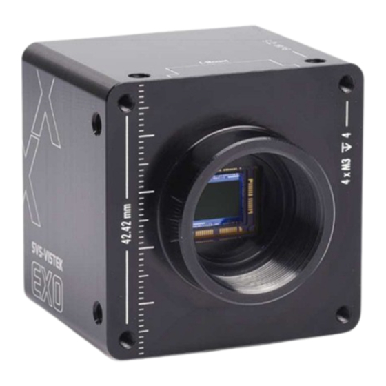
Page 15: The Exo
SVS-VISTEK 4 The EXO The EXO series is a series of machine vision cameras for the low and mid- range resolutions up to 20 MP. The EXO is available with different industry standard interfaces such as GigE Vision, Camera Link and USB3 Vision. - Page 16 4IO adds Light and Functionality 4IO concept with up to 4 switching LED lights Your SVS-Vistek camera is equipped with the innovative 4IO-interface allowing full light control, replacing external strobe controllers. Each of the outputs can be individually configured and managed using pulse- width modulation.
-
Page 17: Feature Description
SVS-VISTEK 5 Feature description This chapter covers features of SVCam cameras. Not every feature might be supported by your specific camera model. For information about the features of your specific model, please refer to the specifications area with your exact model. -
Page 18: Acquisition And Processing Time
SVS-VISTEK 5.1.4 Acquisition and Processing Time The camera has to read the sensor, process the data to a valid image and transfer this to the host computer. Some of these tasks are done in parallel. This implies the data transfer does not end immediately after end of exposure, as the image has to be processed and transferred after exposure. -
Page 19: Color
SVS-VISTEK 5.1.7 Color Color cameras are identical to the monochrome versions. The color pixels are transferred in sequence from the camera, in the same manner as the monochrome, but considered as “raw”-format. CCD with Bayer Pattern The camera sensor has a color mosaic filter called “Bayer” filter pattern named after the person who invented it. -
Page 20: Resolution
SVS-VISTEK 5.1.8 Resolution As mentioned in the specifications, there is a difference between the numerical sensor resolution and the camera resolution. Some pixels towards the borders of the sensor will be used only internally to calibrate sensor values (“dark pixels”). The amount of dark current in these areas is used to adjust the offset. -
Page 21: Gain
SVS-VISTEK 5.1.10 Gain Setting gain above 0 dB (default) is a way to boost the signal coming from the sensor. Especially useful for low light conditions. Setting gain amplifies the signal of individual or binned pixels before the ADC. Referring to photography adding gain corresponds to increasing ISO. -
Page 22: Flip Image
SVS-VISTEK 5.1.11 Flip Image Images can be mirrored horizontally or vertically. Image flip is done inside the memory of the camera, therefore not increasing the CPU load of the PC. original image horizontal flip vertical flip Feature description... -
Page 23: Binning
SVS-VISTEK 5.1.12 Binning Binning provides a way to enhance dynamic range, but at the cost of lower resolution. Binning combines electron charges from neighboring pixels directly on the chip, before readout. Binning is only used with monochrome CCD Sensors. For reducing resolution on color sensors refer to decimation. - Page 24 SVS-VISTEK 2×2 Binning A combination of horizontal and vertical binning. When DVAL signal is enabled only every third pixel in horizontal direction is grabbed. 2x2 binning Feature description...
-
Page 25: Decimation
SVS-VISTEK 5.1.13 Decimation For reducing width or height of an image, decimation can be used. Columns or rows can be ignored. Refer to AOI for reducing data rate by reducing the region you are interested in. Horizontal decimation Vertical decimation... -
Page 26: Camera Features
SVS-VISTEK 5.2 Camera Features 5.2.1 Basic Capture Modes Free Running Free running (fixed frequency) with programmable exposure time. Frames are readout continously and valid data is indicated by LVAL for each line and FVAL for the entire frame. There is no need to trigger the camera in order to get data. Exposure time is programmable via serial interface and calculated by the internal logic of the camera. - Page 27 At the rising edge of the trigger the camera will initiate the exposure. The software provided by SVS-Vistek allows the user to set exposure time e.g. from 60 μs 60 Sec (camera type dependent).
- Page 28 SVS-VISTEK Exposure time can be changed during operation. No frame is distorted during switching time. If the configuration is saved to the EEPROM, the set exposure time will remain also when power is removed. Detailed Info of External Trigger Mode Dagrams below are aquivalent for CCD and CMOS technique.
-
Page 29: System Clock Frequency
SVS-VISTEK 5.2.2 System Clock Frequency Default system clock frequency in almost every SVCam is set to 66.6 MHz. To validate your system frequency refer to: specifications. Using the system clock as reference of time, time settings can only be made in steps. In this example, the transfer rate is 66.7 MHz, thus resulting in steps of 15 ns. -
Page 30: Camera Link Timings
SVS-VISTEK 5.2.4 Camera Link timings It might be interesting to know when “valid data” can be expected exactly. = pixel horizontal [count] = pixel vertical [count] LVAL – t L v d Every line has periods with no valid data. The Duration of None Valid Data between two lines ( ) is three time the Camera Link clock (clk). - Page 31 SVS-VISTEK overview of FVAL and LVAL signal timing on Camera Link more detailed view of LVAL signal timing on Camera Link Example calculation on exo174*CL (1920 / 2) (1/85MHz) > × px in line / sent at once CL_clock ×...
-
Page 32: Read-Out-Control
SVS-VISTEK 5.2.5 Read-Out-Control Read-Out-Control defines a delay between exposure and data transfer. Read-Out-Control is used to program a delay value (time) for the readout from the sensor. With more than one camera connected to a single computer, image acquisition and rendering can cause conflicts for data transfer, on CPU or bus-system. -
Page 33: Lookup Table
SVS-VISTEK 5.2.6 LookUp Table The LookUp Table Feature (LUT) lets the user define certain values to every bit value that comes from the ADC. To visualize a LUT a curve diagram can be used, similar to the diagrams used in photo editing software. -
Page 34: Roi / Aoi
SVS-VISTEK Gamma Correction Using the LookUp Table makes is also possible to implement a logarithmic correction. Commonly called Gamma Correction. Historically Gamma Correction was used to correct the illumination behavior of CRT displays, by compensating brightness-to-voltage with a Gamma value between 1,8 up to 2,55. - Page 35 SVS-VISTEK AOI on a CCD sensor Selecting an AOI will reduce the number of horizontal lines being read. This will reduce the amount of data to be transferred, thus increasing the maximum speed in term of frames per second. With CCD sensors, setting an AOI on the left or right side does not affect the frame rate, as lines must be read out completely.
-
Page 36: Piv
The readout of picture 1 will take place during the second exposure time. So the time between 2 images can be shortened to transfer time only – contact us (@ SVS-VISTEK.com) for camera and sensor specific minimum transfer time/duration. „Triggered with external exposure“ (via pulse width of the Exsync signal) or alternatively „triggered with internal exposure“( set via internal... -
Page 37: Pixel Clock Frequency Selection
Color sensor images are affected, especially red will be higher in intensity than visible with bare eyes. White balance gets much more difficult. Contrast is lower. SVS-VISTEK recommends IR cut filter for high demands on sharpness with monochrome or color sensors. Spectral impact of IR cut filters IR cut filter do influence the spectral sensitivity of the sensor. - Page 38 SVS-VISTEK Figure 4: IR cut filter light transmission Focal impact of filters As an IR cut filter mainly consist of a small layer of glass (1 mm thick) there is an impact on the flange focal distance. Refraction within the layer cause shortening this distance.
-
Page 39: Defect Pixel Correction
(hot pixel) that always are outputting a bright signal. The amount of hot pixels is proportional to exposure time and temperature of the sensor. By default, all known defect pixels or clusters are corrected by SVS-VISTEK as a factory default. Under challenging conditions or high temperature environments defect pixel behaviour might change. -
Page 40: I/O Features
The GenICam properties are organized as a tree. Manufacturers can add more features. With your SVCam, the GenICam tree does have some hardware related extensions, especially in the I/O sector. See the Quick guide install for a short introduction into SVS-Vistek’s GenICam tree. Feature description... -
Page 41: Pwm
SVS-VISTEK 5.3.2 PWM During Pulse Width Modulation (PWM), a duty cycle is modulated by a fixed frequency square wave. This describes the ratio of ON to OFF as duty factor or duty ratio. Why PWM? Many electrical components must be provided with a defined voltage. - Page 42 SVS-VISTEK P W M X A M P L E S O F 25% PWM load 50% PWM load The integrals over both periods 7 and 7 are equal. An equal amount of Photons will be emitted. The intensity of light is the same.
-
Page 43: Driver Circuit Schematics
SVS-VISTEK 5.3.3 Driver Circuit Schematics Camera power supply and power supply for PWM out is 25V max. Power for PWM out has to be supplied via Hirose connector. The open drain outputs are ledged to ground, that means you connect your LED on the positive side to your (light-)power source, the negative LED connector goes to the camera out. -
Page 44: Assigning I/O Lines - Iomux
EPROM. Default setting can be restored from within the Camera. Note: LineSelector translation If you connect the camera with a non- Line0 Output0 SVS-Vistek GigEVision client, you Line1 Output1 might not see the clearnames of the Line2 Output2 lines, but only line numbers. In this Line3... - Page 45 SVS-VISTEK Refer to pinout in input / output connectors when physically wiring. input vector to switch matrix name description io_in(0) trigger input 0 – 24 Volt / RS-232 / opto * io_in(1) trigger input 0 – 24 Volt / RS-232 / opto * io_in(2) trigger input 0 –...
- Page 46 SVS-VISTEK output vector from switch matrix name / register describtion io_out(0) output open drain io_out(1) output open drain io_out(2) output open drain * io_out(3) output open drain * io_txd output, when debug='0' rxd_to_uart1 output (uart_in) trigger output sequenzer_hw_trigger input to module iomux_sequenzer_0...
- Page 47 SVS-VISTEK Example of an IOMUX configuration > The trigger signal comes in on line 0 > Debounce it. connect line 0 to 8: 1000000000000000000000000 signal appears again on line 15 – debouncer out > Use the prescaler to act only on every second pulse.
-
Page 48: Led Strobe Control
SVS-VISTEK 5.3.5 Strobe Control The SVCam 4I/O concept contains an integrated strobe controller. Its controls are integrated into the GenICam tree. With LED lights attached to the outputs, this enables the user to control the light without external devices. Being controlled via GenICam, any GenICam-compliant 3 party software is able to control the light as well. - Page 49 SVS-VISTEK LEDs in Flash Mode Most LED lights can cope with currents higher than specs. This gives you higher light output when light is ON. Please refer to your LED specs if LED overdrive is permitted. By controlling the duty cycle the intensity of light and current can be controlled.
-
Page 50: Sequencer
SVS-VISTEK 5.3.6 Sequencer The sequencer is used when different exposure settings and illuminations are needed in a row. Values to set Description Sequencer interval Duration of the interval Exposure delay after interval start Exposure start Exposure stop related to interval Start... - Page 51 SVS-VISTEK Notes Different exposure / strobe timings are used for illustration. In most cases they will show values same as exposure The resulting exposure time shows the period of sensor light exposure. (‘’masking’’ of exposure time by creating strobe light impulses shorter than exposure time).
- Page 52 SVS-VISTEK As being said before, all these values have to be entered into the camera’s GenICam tree as tic values. The timing values translate like this into tics: Values to set in GenICam Interval 0 (RED) Interval 1 (GREEN) Interval 2 (BLUE) Interval 3 (WHITE)
- Page 53 SVS-VISTEK Sequencer setup with SVCapture Starting with SVCapture 2.5.2, there is a sequencer assistant, providing easy setup of the sequencer settings. The assistant will help you to setup timings for start exposure and lighting and so on. The PWMs are connected to the physical outputs (e.g.
- Page 54 SVS-VISTEK will reflect as following: Feature description...
-
Page 55: Optical Input
If your camera trigger is in the ms range or slower, we recommend to use the optical input. An optical input needs some current for operation. The SVS-Vistek optical input is specified to 5-24V, 8mA. The opto coupler galvanically separates electrical circuits by emitting light on one side and interpreting light in the other. -
Page 56: Plc/Logical Operation On Inputs
SVS-VISTEK 5.3.8 PLC/Logical Operation on Inputs The logic input combines trigger signals with Boolean algorithms. The camera provides AND, NAND, OR, NOR as below. You might combine combine true/false states of the inputs to determine camera actions. The result can be connected to a camera trigger signal or it may be source for the next logical operation with another input. -
Page 57: Serial Data Interfaces
SVS-VISTEK 5.3.9 Serial data interfaces (ANSI EIA/) TIA-232-F RS-232 and RS-422 (from EIA, read as Radio Sector or commonly as Recommended Standard) are technical standards to specify electrical characteristics of digital signalling circuits. Serial connection might be used to control SVCams. These signals are used to send low-power data signals to control exposure, light or lenses (MFT). -
Page 58: Trigger-Edge Sensitivity
SVS-VISTEK 5.3.10 Trigger-Edge Sensitivity Trigger-Edge Sensitivity is implemented by a “schmitt trigger”. Instead of triggering to a certain value Schmitt trigger provides a threshold. Schmitt trigger noise suppression 5.3.11 Debouncing Trigger Signals Bounces or glitches caused by a switch can be avoided by software within the SVCam. - Page 59 SVS-VISTEK Therefor the signal will not be accepted till it lasts at least a certain time. Use the IO Assignment tool to place and enable the debouncer module in between the “trigger” (schmitt trigger) and the input source (e.g.: line DebouncDuration register can be set in multiples of 15ns (implement of system clock).
-
Page 60: Prescale
SVS-VISTEK 5.3.12 Prescale The Prescaler function can be used for masking off input pulses by applying a divisor with a 4-bit word, resulting in 16 unique settings. > Reducing count of interpreted trigger signal > Use the prescaler to ignore a certain count of trigger signals. -
Page 61: Specifications
SVS-VISTEK Specifications All specifications can be viewed as well on our website, www.svs- vistek.com. We are proud to have ongoing development on our cameras, so specs might change and new features being added. Spectral response curves are sensor only and do not include camera spectral response modifications due to filters or cover glass. -
Page 62: Exo694*Cl
SVS-VISTEK 6.1 exo694*CL Model exo694CCL exo694MCL family active pixel w x h 2752 x 2200 2752 x 2200 max. frame rate 25 fps 25 fps chroma color mono interface Camera Link Base Camera Link Base sensor name ICX694AQG ICX694ALG sensor manufacturer... - Page 63 SVS-VISTEK PWM power out trigger IN TTL-24 V outputs open drain optical in / out 1 / - 1 / - RS-232 in / out 1 / 1 1 / 1 RS-422 in / out - / - - / - power supply 10...25 V...
- Page 64 SVS-VISTEK Spectral sensitivity characteristics Color Figure 6: IMX694LQR Mono Figure 7: IMX694LLR Specifications...
-
Page 65: Exo814*Cl
SVS-VISTEK 6.2 exo814*CL Model exo814CCL exo814MCL family active pixel w x h 3360 x 2712 3360 x 2712 max. frame rate 18 fps 18 fps chroma color mono interface Camera Link Base Camera Link Base sensor name ICX814AQG ICX814ALG sensor manufacturer... - Page 66 SVS-VISTEK PWM power out trigger IN TTL-24 V outputs open drain optical in / out 1 / - 1 / - RS-232 in / out 1 / 1 1 / 1 RS-422 in / out - / - - / - power supply 10...25 V...
- Page 67 SVS-VISTEK Spectral sensitivity characteristics Color Mono Specifications...
-
Page 68: Dimensions
SVS-VISTEK 7 Dimensions All length units in mm. Find drawings in the web download area at https://www.svs-vistek.com/en/support/svs-support-download-center.php CAD step files available with valid login at SVS-VISTEK.com Dimensions... -
Page 69: Exo694*Cl, Exo695*Cl, Exo814*Cl, Exo815*Cl, Exo834*Cl
SVS-VISTEK 7.1 exo694*CL, exo695*CL, exo814*CL, exo815*CL, exo834*CL front side Left Dimensions... - Page 70 SVS-VISTEK Side Right Dimensions...
- Page 71 SVS-VISTEK Bottom Back Dimensions...
- Page 72 SVS-VISTEK Dimensions...
-
Page 73: C & Cs Mount
SVS-VISTEK 7.2 C & CS mount For C & CS mounts, different back focus distances from sensor to lens. > C-mount: 17,526 mm > CS-mount: 12,526 mm > Diameter: 1 inch > Screw threading: 1/32 inch CS-mount cameras accept C and CS types of lenses. C-mount lenses require an additional 5mm adapter ring. - Page 74 SVS-VISTEK Note regarding lens screw in depth: Maximum C-mount screw-in depth is 9.1mm or 10.6mm image side flange distance if diameter does not exceed 20.6mm. Dimensions...
-
Page 75: Terms Of Warranty
SVS-VISTEK 8 Terms of warranty Seller warrants that the article to be delivered under this order will be free from Standard Products Warranty and defects in material and workmanship under normal use and service for a period Adjustment of 2 years from date of shipment. The liability of Seller under this warranty is limited solely to replacing or repairing or issuing credit (at the discretion of Seller) for such products that become defective during the warranty period. -
Page 76: Faq
SVS-VISTEK 9 FAQ Problem Solution Camera does not respond to light. Check if camera is set to “Mode 0“. I.e. free running with programmed exposure ctrl. When done, check with the program “Convenient Cam“ if you can read back any data from the camera, such as “Mode“, “type“ of CCD, exposure time settings, etc.. -
Page 77: Glossary Of Terms
SVS-VISTEK 10 Glossary of Terms Spherical aberration occurs when light rays enter near the edge of the lens; Aberration Chromatic aberration is caused by different refractive indexes of different wavelengths of the light. (Blue is more refractive than red) Analogue-to-Digital Converter, also known as A/D converter In optics, Aperture defines a hole or an opening through which light travels. - Page 78 A camera RAW image file contains minimally processed data from the image sensor. It is referred as raw in its meaning. SVS-VISTEK plays out RAW only. Read-Out control defines a delay between exposure and image readout. It...
- Page 79 SVS-VISTEK A bright light source with a very short light pulse. Ideal for use with Strobe light industrial cameras, e.g. for “freezing” the image capture of fast moving objects. Can often be a substitute for the electronic shutter of the image sensor.
Need help?
Do you have a question about the exo694 CL and is the answer not in the manual?
Questions and answers