Table of Contents
Advertisement
Quick Links
Advertisement
Table of Contents

Related Manuals for SVS-Vistek EVO Series


Summary of Contents for SVS-Vistek EVO Series
- Page 1 Manual EVO series evo1050, evo2050, evo2150, eco4050, evo4070, evo8051 2.26.2018...
- Page 2 Distributor Information PYRAMID IMAGING, INC. 945 E. 11th Avenue Tampa, FL 33605 Pyramid Imaging Tel.: +1 (813) 984-0125 Fax: +1 (866) 874-9521 Mail: sales@pyramidimaging.com Web: https://pyramidimaging.com This Operation Manual is based on the following standards: DIN EN 62079 DIN EN ISO 12100 ISO Guide 37 DIN ISO 3864-2 DIN ISO 3864-4...
-
Page 3: Table Of Contents
Contents Contents Safety Messages ............6 Legal Information ............. 7 The EVO Series ............8 Compact Power ............8 GigE-Vision features ..........8 4IO adds Light and Functionality ........ 9 Getting Started ............10 Contents of Camera Set .......... 10 Power supply ............ - Page 4 Contents 7.1.8 Auto Luminance ............43 7.1.9 Bit-Depth ..............44 7.1.10 Color ................. 46 7.1.11 Resolution – active & effective ........46 7.1.12 Offset ................ 48 7.1.13 Gain ................49 7.1.14 Flip Image ..............50 7.1.15 Binning ..............51 7.1.16 Decimation ..............
- Page 5 Contents Troubleshooting ..........127 10.1 FAQ ............... 127 10.2 Support Request Form / Check List ...... 128 IP protection classes .......... 130 Glossary of Terms ..........132 Index ............... 135...
-
Page 6: Safety Messages
MANDATORY ACTION! A white graphical symbol inside a blue circle defines a safety sign that indicates that an action shall be taken to avoid a hazard. Cross-reference NOTICE Provides references and tips Figure 1: Safety messages SVS-VISTEK– Compact Power... -
Page 7: Legal Information
Customers, integrators and end users of SVS-Vistek products might sell these products and agree to do so at their own risk, as SVS-Vistek will not take any liability for any damage from improper use or sale. -
Page 8: The Evo Series
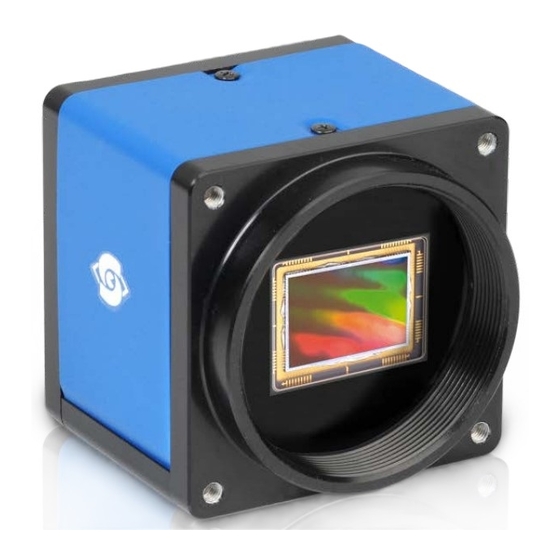
3 The EVO Series 3.1 Compact Power Maximum camera technology in the smallest package. With high-end On Semi sensors the cameras of the SVCam-EVO series offer extraordinary performance in a very compact housing. Maximum of high-tech in a minimum enclosure Our expertise is united to ensure you get a reliable imaging tool for securing the decisive advantage in your system. -
Page 9: 4Io Adds Light And Functionality
SVS-VISTEK 3.3 4IO adds Light and Functionality Your SVS-Vistek camera is equipped with the innovative 4IO-interface Figure 1: 4IO concept with up to 4 switching LED lights allowing full light control, replacing external strobe controllers. Each of the outputs can be individually configured and managed using pulse- width modulation. -
Page 10: Getting Started
Red slow ( 1 Hz ) Problem with initialization Red quickly ( 8 Hz) Camera overheating Blue permanent Waiting for trigger Cyan permanent Exposure active Violet permanent Readout/FVAL Figure 1: Camera status LED codes SVS-VISTEK–Getting Started Contents of Camera Set... -
Page 11: Software
(GenICam drivers and transport layer DDLs) SVCapture 2.x is a XML based software tool provided for free. It is created to show the capabilities of your SVS-Vistek camera and to show/modify values to your cam. Get control of exposure timing, trigger delay, image correction etc. or control up to 4 LED lights connected to the SVCam directly via the PC. - Page 12 SVS-VISTEK Software Setup Installation prosecco may differ from PC to PC. It is recommended to install the whole software package. Copy/expand the installation executable file to your hard drive. Run installation Read and accept the terms of license agreement Choose destination folder...
- Page 13 SVS-VISTEK Install the USB 3.0 Driver Generic driver included in the windows system will not match all SVS-VISTEK USB3 Vision features. Start installation System, warning The installer will modify your system (USB 3.0 driver); there for windows systems will warn you with an interrupt.
- Page 14 SVS-VISTEK Installation will proceed Installation completed Getting Started...
- Page 15 SVS-VISTEK Initialization I R S T L A U N C H The software is XML based. So in case there is no Camera connected to the USB slot, no XML camera properties can be loaded, no values to control are available.
- Page 16 SVS-VISTEK Conform to GenICam all control features will be listed in a flat tree diagram. Getting Started...
- Page 17 SVS-VISTEK USB 3.0 driver The USB 3.0 driver You can find the USB 3.0 driver within your hardware manager: Getting Started...
-
Page 18: Update Firmware
Tool.exe” and the firmware file (download it from website, login area) matching your camera model. Execute firmware update > Download the GigE firmware tool and the firmware file from the SVS-Vistek website. > Unpack everything into any folder, e.g. “C:\temp” > Ensure proper network configuration >... -
Page 19: Gige Ip Setup
SVCapture. Automatic camera detection By default, SVS-Vistek GigE Vision cameras are trying to acquire a valid network address vie LLA or DHCP from the network. For finding and accessing your camera, start SVCapture on your computer. - Page 20 SVS-VISTEK SVIPConfig SVIPConfig allows to > Assign a new IP address (make sure the address is unique and that it is valid in the current subnet) > Save a specific address as a permanent address to the camera (Persistent) >...
-
Page 21: Driver Circuit Schematics
SVS-VISTEK 4.5 Driver Circuit Schematics Figure 5: basic Illustration of driver circuit Getting Started... -
Page 22: Connectors
Use the upper right network port for single line operation. NOTICE Dual GigE connection is required only if single network connection does not provide sufficient bandwidth. For dual GigE operation, 2 NICs need to be teamed. NIC teaming is a feature of the operating system SVS-VISTEK–Connectors Dual GigE Vision... - Page 23 SVS-VISTEK Connectors...
-
Page 24: Teaming Dual Gige
SVS-VISTEK 5.1.3 Teaming Dual GigE NOTICE Windows 10 does not support static link aggregation. You need to run win7, win8, macOS or linux if you want to use dual GigE For higher transfer rates on GigE, you might want to team 2 GigE ports together. - Page 25 SVS-VISTEK Figure 8: team wizard Choose Static Link Aggregation, next and finish. Figure 9: setting Static Link Aggregation (SLA) Jumbo Frames The transport efficiency in the streaming channel can be improved by using “jumbo frames”. This will reduce overhead caused by maintaining header data upon each data packet sent.
-
Page 26: Xml Files
SVS-VISTEK NOTICE Resends result in higher consumption of bandwidths and will lead to drop frames. High quality cables prevent resends. 5.1.4 XML Files According to the GigE Vision standard a GigE camera provides an XML file that defines the camera’s capabilities and current settings. -
Page 27: Input / Output Connectors
SVS-VISTEK 5.2 Input / output connectors For further information using the breakout box and simplifying I/O connection refer to SVCam Sensor Actor manual (with Murr and Phoenix breakout boxes). To be found separate within the USP manuals. Hirose™ 12Pin For detailed information about switching lights from inside the camera, refer to strobe control. -
Page 28: Dimensions
Find drawings in the web download area at https://www.svs-vistek.com/en/support/svs-support-download-center.php CAD step files available with valid login at SVS-VISTEK.com 6.1 EVO GigE C-mount CAD step files available on DVD or SVS-VISTEK.com. Including: evo1050CFLGEA, evo1050CFLGEA4IO, evo1050CFLGEC, evo1050CFLGEC4IO, evo1050MFLGEA, evo1050MFLGEA4IO, evo1050MFLGEC, evo1050MFLGEC4IO, evo2050CFLGEA,... - Page 29 SVS-VISTEK Dimensions...
-
Page 30: Evo Gige M42 Mount
SVS-VISTEK 6.2 EVO GigE M42 mount CAD step files available on DVD or SVS-VISTEK.com. Including: evo4070CFLGEA, evo4070CFLGEA4IO, evo4070CFLGEC, evo4070CFLGEC4IO, evo4070MFLGEA, evo4070MFLGEA4IO, Dimensions... - Page 31 SVS-VISTEK evo4070MFLGEC, evo4070MFLGEC4IO, evo6040CBGEB, evo6040MBGEB, evo8050CFLGEA, evo8050CFLGEC, evo8050CFLGEC4IO, evo8050MFLGEA, evo8050MFLGEA4IO, evo8050MFLGEC, evo8050MFLGEC4IO, evo8051CFLGEA, evo8051CFLGEA4IO, evo8051CFLGEC, evo8051CFLGEC4IO, evo8051MFLGEA, evo8051MFLGEA4IO, evo8051MFLGEC, evo8051MFLGEC4IO Dimensions...
- Page 32 SVS-VISTEK Dimensions...
- Page 33 SVS-VISTEK Dimensions...
-
Page 34: C & Cs Mount
Inch CS-Mount Cameras accept both types of lenses. C-Mount lenses require a 5mm adapter ring to be fitted. (Also available at SVS-VISTEK) C-Mount Cameras only accept C mount lenses as the flange to sensor distance does not allow a CS mount lens close enough to the Sensor to achieve a focused image. -
Page 35: M42 Mount
SVS-VISTEK M42 Mount Diameter: 42 mm Thread pitch 1.0 mm Back focus distance from sensor to flange of the camera: 11.48 mm Distance from sensor surface to lens differs depending on lens specifications and how far the lens is screwed in. -
Page 36: Feature-Set
Charge is an integration of time and light intensity on the element. Like this the image gets brighter the longer the CCD cell is exposed to light. The sensor converts light into charge and transports it to an amplifier and subsequently to the analog to digital converter (ADC). SVS-VISTEK–Feature-Set Basic Understanding... -
Page 37: Interline Transfer
SVS-VISTEK 7.1.2 Interline Transfer Interline Transfer is only used in CCD sensors. With a single pixel clock the charge from each pixel is transferred to the vertical shift register. At this time, the light sensitive elements are again collecting light. The charge in the vertical registers is transferred line by line into the horizontal shift register. -
Page 38: Global Shutter
SVS-VISTEK 7.1.3 Global shutter The shutter is describing the functionality of exposing the light sensitive pixels of the sensor to light for a limited time. With Global shutterall pixels are exposed to light at the same time. All pixel will be exposed to light at the same starting point, and all pixel light exposure will stop at the same time. - Page 39 SVS-VISTEK Figure 2: All pixel lines are sensitive to light the same time All pixels are open the same time. You might flash at any time within exposure time. Feature-Set...
-
Page 40: Rolling Shutter
SVS-VISTEK 7.1.4 Rolling Shutter Rolling shutter is a method of reading out a CMOS sensor, where the whole scene is scanned line after line very rapidly. Rolling shutter cameras in general are more sensitive in their light response than global shutter ones. - Page 41 SVS-VISTEK Figure 20: Rolling shutter lines light sensitivity versus time As shown here, after triggering only part of the sensor is sensitive to light (scanning time). As soon as scanning time has finished, all pixels are sensitive to light, the sensor is fully open. While being fully open this is the time where flashing should happen.
-
Page 42: Frames Per Second
SVS-VISTEK 7.1.5 Frames per Second Frames per second, or frame rate describes the number of frames output per second. The inverse (1/ frame rate) defines the frame time. frame per second frame time (Exposure) applicable standard 0,25 500ms 41,6 � ms... -
Page 43: Exposure
SVS-VISTEK 7.1.7 Exposure See various exposure and timing modes in chapter: Basic capture modes. Combine various exposure timings with PWM LED illumination, refer to sequencer. Setting Exposure time Exposure time can be set by width of the external or internal triggers or programmed by a given value. -
Page 44: Bit-Depth
SVS-VISTEK 7.1.9 Bit-Depth Values of brighness are internally represented by numbers. Numbers are represented by bytes, consisting out of single bits. The number of bits for brightness representation is limiting the number of brightness values or colour values that can be represented. Bit depth defines how many unique colors or grey levels are available in an image after digitization. - Page 45 SVS-VISTEK Figure 22: Figure of original picture - black & white Figure 23: Reduced color depth quantification Feature-Set...
-
Page 46: Color
SVS-VISTEK 7.1.10 Color Color cameras are identical to the monochrome versions. The color pixels are transferred in sequence from the camera, in the same manner as the monochrome, but considered as “raw”-format. The camera sensor has a color mosaic filter called “Bayer” filter pattern named after the person who invented it. - Page 47 SVS-VISTEK These pixels are totally darkened. The amount of dark current in these areas is used to adjust the offset. Figure 26: Active and effective sensor pixels Feature-Set...
-
Page 48: Offset
SVS-VISTEK 7.1.12 Offset For physical reasons the output of a sensor will never be zero, even the camera is placed in total darkness or simply closed. Always there will be noise or randomly appearing electrons that will be detected as a signal (dark noise: noise generated without light exposure). -
Page 49: Gain
SVS-VISTEK 7.1.13 Gain Setting gain above 0 dB (default) is another way to boost the signal coming from the sensor. Especially useful for low light conditions. Setting Gain amplifies the signal of individual or binned pixels before the ADC. Referring to Photography adding gain corresponds to increasing ISO. -
Page 50: Flip Image
SVS-VISTEK 7.1.14 Flip Image Images can be mirrored horizontally or vertically. Image flip is done inside the memory of the camera, therefore not increasing the CPU load of the PC. Figure 5: original image Figure 6: horizontal flip Figure 7: vertical flip... -
Page 51: Binning
SVS-VISTEK 7.1.15 Binning Binning provides a way to enhance dynamic range, but at the cost of lower resolution. Instead of reading out each individual pixel, binning combines charge from neighboring pixels directly on the chip, before readout. Binning is only used with monochrome CCD Sensors. For reducing resolution on color sensors refer to decimation. -
Page 52: Decimation
SVS-VISTEK When DVAL signal is enabled only every third pixel in horizontal direction is grabbed. Figure 32: Illustration of 2x2 binning 7.1.16 Decimation For reducing width or height of an image, decimation can be used. Columns or rows can be ignored. - Page 53 (as soon as there is enough time later on to deliver the images) (not applicable to USB cameras) Please note, as soon as the internal memory buffer is filled up, frames will be dropped. Due to this reason, SVS-Vistek camers provide up to 512MB image buffer memory. Feature-Set...
-
Page 54: Camera Features
SVS-VISTEK 7.2 Camera Features 7.2.1 System Clock Frequency Default system clock frequency in almost every SVCam is set to 66.6 MHz. To validate your system frequency refer to: specifications. Using the system clock as reference of time, time settings can only be made in steps. -
Page 55: Basic Capture Modes
SVS-VISTEK 7.2.4 Basic Capture Modes Free Running Free running (fixed frequency) with programmable exposure time. Frames are readout continously and valid data is indicated by LVAL for each line and FVAL for the entire frame. There is no need to trigger the camera in order to get data. Exposure time is programmable via serial interface and calculated by the internal logic of the camera. -
Page 56: Software Trigger
At the rising edge of the trigger the camera will initiate the exposure. The software provided by SVS-Vistek allows the user to set exposure time e.g. from 60 μs 60 Sec (camera type dependent). - Page 57 SVS-VISTEK Feature-Set...
-
Page 58: Lookup Table
SVS-VISTEK 7.2.5 LookUp Table The LookUp Table Feature (LUT) lets the user define certain values to every bit value that comes from the ADC. To visualize a LUT a curve diagram can be used, similar to the diagrams used in photo editing software. -
Page 59: Roi / Aoi
SVS-VISTEK Gamma Correction Using the LookUp Table makes is also possible to implement a logarithmic correction. Commonly called Gamma Correction. Historically Gamma Correction was used to correct the illumination behavior of CRT displays, by compensating brightness-to-voltage with a Gamma value between 1,8 up to 2,55. - Page 60 SVS-VISTEK Figure 38: AOI on a CCD sensor Selecting an AOI will reduce the number of horizontal lines being read. This will reduce the amount of data to be transferred, thus increasing the maximum speed in term of frames per second.
-
Page 61: Defect Pixel Correction
All image sensor have defect pixels in a lesser or greater extent. The number of defects determines the quality grade and the value of all sensors integrated by SVS-VISTEK. Defect Pixels either be dark pixels, i.e. that don’t collect any light, or bright pixels (hot pixel) that always are outputting a bright signal. -
Page 62: Shading Correction
SVS-VISTEK 7.2.8 Shading Correction The interactions between objects, illumination, and the camera lens might lead to a non-uniform flatfield in brightness. Shading describes the non- uniformity of brightness from one edge to the other or center towards edge(s). This shading can be caused by non-... -
Page 63: I/O Features
SVS-VISTEK 7.3 I/O Features 7.3.1 Assigning I/O Lines – IOMUX The IOMUX is best described as a switch matrix. It connects inputs, and outputs with the various functions of SVCam I/O. It also allows combining inputs with Boolean arguments. Figure 41: "IN0" connected to "debouncer"... - Page 64 EPROM. Default setting can be restored from within the Camera. Note: If you connect the camera with a non-SVS-Vistek GigEVision client, you might not see the clearnames of the lines, but only line numbers. In this case, use this list of line names...
- Page 65 SVS-VISTEK Refer to pinout in input / output connectors when physically wiring. Also the IOMUX can be illustrated as a three dimensional dice. Long address spaces indicate which signals are routed to witch module within the camera. Figure 42: I/O switch matrix...
- Page 66 SVS-VISTEK Figure 43: I/O Lines with open end indicate physical in- and outputs Feature-Set...
- Page 67 SVS-VISTEK input vector to switch matrix name description io_in(0) trigger input 0 – 24 Volt / RS-232 / opto * io_in(1) trigger input 0 – 24 Volt / RS-232 / opto * io_in(2) trigger input 0 – 24 Volt / RS-232 / opto * io_in(3) trigger input 0 –...
- Page 68 SVS-VISTEK output vector from switch matrix name / register describtion io_out(0) output open drain io_out(1) output open drain io_out(2) output open drain * io_out(3) output open drain * io_txd output, when debug='0' rxd_to_uart1 output (uart_in) trigger output sequenzer_hw_trigger input to module iomux_sequenzer_0...
- Page 69 SVS-VISTEK Example of an IOMUX configuration > The trigger signal comes in on line 0 > Debounce it. connect line 0 to 8: 1000000000000000000000000 signal appears again on line 15 – debouncer out > Use the prescaler to act only on every second pulse.
-
Page 70: Strobe Control
SVS-VISTEK 7.3.2 Strobe Control Drive LED lights form within your camera. Control them via ethernet. Figure 44: use the breakout box to simplify your wiring > SVCam cameras have built-in MOSFETs that can drive up to 3 Amperes. > This allows using the cameras as a strobe controller – saving costs. - Page 71 SVS-VISTEK 2 IO’s high voltage drain Figure 45: Illustration of two LEDs switched internal by the camera For detailed connector pin out refer to Connectors. For further information using the breakout box and simplifying OIs refer SVCam Connectivity manual. To be found separate within the USP manuals.
- Page 72 SVS-VISTEK Figure 47: Illustration of schematic wiring with 4IO model using the break out box (matrix) The pulseloop module A fully programmable timer/counter function with four individual pulse generators (pulseloop0 - 3) that can be combined with all SVCam I/O functions, as well as physical inputs and outputs.
- Page 73 SVS-VISTEK Camera cascade Three cameras are triggered in cascade where the first camera is the master receiving the external trigger, and the master subsequently triggers the two slave cameras. Figure 49: pulseloop – activating three cameras O D U L E P U L S E L O O P...
- Page 74 SVS-VISTEK LEDs in Continuous Mode Example Calculation “No Flash” (CW Mode) Voltage drop al 5 LEDs, 2,2 V per LED (see spec. of LED) 11 V Max. continuous current (see spec. of LED) 250 mA Voltage Supply 24 V Voltage drop at Resistor (24 V – 11 V) 13 V ����...
- Page 75 SVS-VISTEK Strobe Timing Ex p osu re D e l a y A value, representing the time between the (logical) positive edge of trigger pulse and start of integration time. Unit is 1μs. Default is 0μs. Str ob e Pol a ri ty Positive or negative polarity of the hardware strobe output can be selected.
- Page 76 SVS-VISTEK Strobe Control Example Setup Figure 50: Illustration of an application using the 4IO Feature-Set...
-
Page 77: Sequencer
SVS-VISTEK 7.3.3 Sequencer The sequencer is used when different exposure settings and illuminations are needed in a row. E.g. the scenario to be captured may occur in three different versions and should therefore be recorded with three different light source settings. - Page 78 SVS-VISTEK Example: Values to set Interval 0 Interval 1 Interval 2 Sequencer 1.000.000 µs 1.000.000 µs 1.000.000 µs Interval (1s) (1s) (1s) Exposure Start 220.000 µs 875.000 µs 190.000 µs Exposure Stop 700.000 µs 125.000 µs 720.000 µs Strobe Start 110.000 µs...
-
Page 79: Pwm
SVS-VISTEK 7.3.4 PWM Pulse width modulation Description of the function used within the sequencer or implemented by the pulseloop module During Pulse Width Modulation, a duty cycle is modulated by a fixed frequency square wave. This describes the ratio of ON to OFF as duty factor or duty ratio. - Page 80 SVS-VISTEK P W M : H E I N T E N S I T Y O F A That duty ratio is calculated as: Δ% = t / T. It is written about the value of "t" as PWMChange0-3[SeqSelector] per sequence into the Registry.
-
Page 81: Plc/Logical Operation On Inputs
SVS-VISTEK 7.3.5 PLC/Logical Operation on Inputs The logic input combines trigger signals with Boolean algorithms. The camera provides AND, NAND, OR, NOR as below. You might connect 2 signals on the logic input. The result can be connected to a camera trigger signal or it may be source for the next logical operation with another input. -
Page 82: Serial Data Interfaces
SVS-VISTEK If neither input is high, a low pulse_out (0) results. Combine trigger input one and two. Y = A v B No trigger input – one nor two – results in a high or a low level pulse_out. Invert both trigger inputs. By inverting the resulting pulse_out you will get the NOR I pulse Y = A ⊽... - Page 83 SVS-VISTEK In the SVCam’s these signals are used to send low-power data signals to control light or lenses (MFT). Serial interface Parameter RS-232 RS-422 Maximum open-circuit voltage ±25 V ±6 V Max Differential Voltage 25 V 10 V Min. Signal Range ±3 V...
- Page 84 SVS-VISTEK UART Packaging Data into containers (adding start and stop bits) is implemented by the UART (Universal Asynchronous Receiver Transmitter) Figure 55: UART encoding of a data stream RS-422 RS-422 is a differential low voltage communication standard. Figure 56: LVDS signal – no return to zero volt...
-
Page 85: Trigger-Edge Sensitivity
SVS-VISTEK 7.3.7 Trigger-Edge Sensitivity Trigger-Edge Sensitivity is implemented by a “schmitt trigger”. Instead of triggering to a certain value Schmitt trigger provides a threshold. Figure 8: Schmitt trigger noise suppression 7.3.8 Debouncing Trigger Signals Bounces or glitches caused by a switch can be avoided by software within the SVCam. - Page 86 SVS-VISTEK Therefor the signal will not be accepted till it lasts at least a certain time. Use the IO Assignment tool to place and enable the debouncer module in between the “trigger” (schmitt trigger) and the input source (e.g.: line DebouncDuration register can be set in multiples of 15ns (implement of system clock).
-
Page 87: Prescale
SVS-VISTEK 7.3.9 Prescale The Prescaler function can be used for masking off input pulses by applying a divisor with a 4-bit word, resulting in 16 unique settings. > Reducing count of interpreted trigger signal > Use the prescaler to ignore a certain count of trigger signals. -
Page 88: Ir Cut Filter
SVS-VISTEK 7.4 IR Cut Filter To avoid influences of infrared light to your image, cameras are equipped with an IR cut filter or an anti-refection coated glass (AR filter). In addition filters raise the protection class of the camera by protecting the sensor and camera internals from environmental influences. - Page 89 White balance gets much more difficult. Contrasts get lost because of IR light influencing also blue and green pixels. SVS-VISTEK recommends IR cut filter for high demands on color or sharpness whether monochrome or color sensors. Spectral Impact of IR Cut Filters IR cut filter do influence the spectral sensitivity of the sensor.
-
Page 90: Specifications
Specifications All specifications can be viewed as well on our website, www.svs- vistek.com We are proud to have ongoing development on our cameras, so specs might change and new features being added. SVS-VISTEK–Specifications IR Cut Filter... -
Page 91: Evo1050*Flgea
SVS-VISTEK Evo1050*FLGEA Model evo1050MFLGEA evo1050CFLGEA family active pixel w x h 1024 x 1024 1024 x 1024 max. frame rate 147 fps 147 fps chroma mono color interface Dual GigE Vision Dual GigE Vision sensor name KAI-01050-A KAI-01050-C sensor manufacturer... - Page 92 160 g protection class IP40 IP40 power consumption 7,0 W 7,0 W ambient temperature -10...45°C -10...45°C rel. humidity non-condensing 10…90 % 10…90 % status production production (1) please refer to model drawings © SVS-VISTEK February 26, 2018 February 26, 2018 Specifications...
-
Page 93: Evo1050*Flgec
SVS-VISTEK Evo1050*FLGEC Model evo1050MFLGEC evo1050CFLGEC family active pixel w x h 1024 x 1024 1024 x 1024 max. frame rate 121 fps 121 fps chroma mono color interface Dual GigE Vision Dual GigE Vision sensor name KAI-01050-A KAI-01050-C sensor manufacturer... - Page 94 160 g protection class IP40 IP40 power consumption 6,0 W 6,0 W ambient temperature -10...45°C -10...45°C rel. humidity non-condensing 10…90 % 10…90 % status production production (1) please refer to model drawings © SVS-VISTEK February 26, 2018 February 26, 2018 Specifications...
- Page 95 SVS-VISTEK Spectral Sensitivity Characteristics KAI-01050-C Spectral Sensitivity Characteristics KAI-01050-A Specifications...
-
Page 96: Evo2050*Flgea
SVS-VISTEK Evo2050*FLGEA Model evo2050MFLGEA evo2050CFLGEA family active pixel w x h 1600 x 1200 1600 x 1200 max. frame rate 81,8 fps 81,8 fps chroma mono color interface Dual GigE Vision Dual GigE Vision sensor name KAI-02050-A KAI-02050-C sensor manufacturer... - Page 97 160 g protection class IP40 IP40 power consumption 7,0 W 6,0 W ambient temperature -10...45°C -10...45°C rel. humidity non-condensing 10…90 % 10…90 % status production production (1) please refer to model drawings © SVS-VISTEK February 26, 2018 February 26, 2018 Specifications...
-
Page 98: Evo2050*Flgec
SVS-VISTEK Evo2050*FLGEC Model evo2050MFLGEC evo2050CFLGEC family active pixel w x h 1600 x 1200 1600 x 1200 max. frame rate 65,4 fps 65,4 fps chroma mono color interface Dual GigE Vision Dual GigE Vision sensor name KAI-02050-A KAI-02050-C sensor manufacturer... - Page 99 160 g protection class IP40 IP40 power consumption 6,0 W 7,0 W ambient temperature -10...45°C -10...45°C rel. humidity non-condensing 10…90 % 10…90 % status production production (1) please refer to model drawings © SVS-VISTEK February 26, 2018 February 26, 2018 Specifications...
- Page 100 SVS-VISTEK Spectral Sensitivity Characteristics KAI-02050-C Spectral Sensitivity Characteristics KAI-02050-A Specifications...
-
Page 101: Evo2150*Flgea
SVS-VISTEK Evo2150*FLGEA Model evo2150MFLGEA evo2150CFLGEA family active pixel w x h 1920 x 1080 1920 x 1080 max. frame rate 78 fps 78 fps chroma mono color interface Dual GigE Vision Dual GigE Vision sensor name KAI-02150-A KAI-02150-C sensor manufacturer... - Page 102 160 g protection class IP40 IP40 power consumption 7,0 W 7,0 W ambient temperature -10...45°C -10...45°C rel. humidity non-condensing 10…90 % 10…90 % status production production (1) please refer to model drawings © SVS-VISTEK February 26, 2018 February 26, 2018 Specifications...
-
Page 103: Evo2150*Flgec
SVS-VISTEK Evo2150*FLGEC Model evo2150MFLGEC evo2150CFLGEC family active pixel w x h 1920 x 1080 1920 x 1080 max. frame rate 62,4 fps 62,4 fps chroma mono color interface Dual GigE Vision Dual GigE Vision sensor name KAI-02150-A KAI-02150-C sensor manufacturer... - Page 104 160 g protection class IP40 IP40 power consumption 6,0 W 6,0 W ambient temperature -10...45°C -10...45°C rel. humidity non-condensing 10…90 % 10…90 % status production production (1) please refer to model drawings © SVS-VISTEK February 26, 2018 February 26, 2018 Specifications...
- Page 105 SVS-VISTEK Spectral Sensitivity Characteristics KAI-02150-C Spectral Sensitivity Characteristics KAI-02150-A Specifications...
-
Page 106: Evo4050*Flgea
SVS-VISTEK Evo4050*FLGEA Model evo4050CFLGEA evo4050MFLGEA family active pixel w x h 2336 x 1752 2336 x 1752 max. frame rate 41,6 fps 41,6 fps chroma color mono interface Dual GigE Vision Dual GigE Vision sensor name KAI-04050-C KAI-04050-A sensor manufacturer... - Page 107 160 g protection class IP40 IP40 power consumption 7,0 W 7,0 W ambient temperature -10...45°C -10...45°C rel. humidity non-condensing 10…90 % 10…90 % status production production (1) please refer to model drawings © SVS-VISTEK February 26, 2018 February 26, 2018 Specifications...
-
Page 108: Evo4050*Flgec
SVS-VISTEK Evo4050*FLGEC Model evo4050MFLGEC evo4050CFLGEC family active pixel w x h 2336 x 1752 2336 x 1752 max. frame rate 33,2 fps 33,2 fps chroma mono color interface Dual GigE Vision Dual GigE Vision sensor name KAI-04050-A KAI-04050-C sensor manufacturer... - Page 109 160 g protection class IP40 IP40 power consumption 6,0 W 6,0 W ambient temperature -10...45°C -10...45°C rel. humidity non-condensing 10…90 % 10…90 % status production production (1) please refer to model drawings © SVS-VISTEK February 26, 2018 February 26, 2018 Specifications...
- Page 110 SVS-VISTEK Spectral Sensitivity Characteristics KAI-04050-C Spectral Sensitivity Characteristics KAI-04050-A Specifications...
-
Page 111: Evo4070*Flgea
SVS-VISTEK 8.9 Evo4070*FLGEA Model evo4050CFLGEA evo4050MFLGEA family active pixel w x h 2336 x 1752 2336 x 1752 max. frame rate 41,6 fps 41,6 fps chroma color mono interface Dual GigE Vision Dual GigE Vision sensor name KAI-04050-C KAI-04050-A sensor manufacturer... - Page 112 160 g protection class IP40 IP40 power consumption 7,0 W 7,0 W ambient temperature -10...45°C -10...45°C rel. humidity non-condensing 10…90 % 10…90 % status production production (1) please refer to model drawings © SVS-VISTEK February 26, 2018 February 26, 2018 Specifications...
-
Page 113: Evo4070*Flgec
SVS-VISTEK 8.10 Evo4070*FLGEC Model evo4070CFLGEC evo4070MFLGEC family active pixel w x h 2048 x 2048 2048 x 2048 max. frame rate 31,4 fps 31,4 fps chroma color mono interface Dual GigE Vision Dual GigE Vision sensor name KAI-4070-C KAI-4070-A sensor manufacturer... - Page 114 SVS-VISTEK trigger intern / extern / soft x / x / x x / x / x trigger edge high / low x / x x / x sequencer PWM power out trigger IN TTL-24 V outputs open drain optical in / out...
- Page 115 SVS-VISTEK Spectral Sensitivity Characteristics KAI-04070-C Spectral Sensitivity Characteristics KAI-04070-A Specifications...
-
Page 116: Evo8050*Flgea
SVS-VISTEK 8.11 Evo8050*FLGEA Model evo8050MFLGEA evo8050CFLGEA family active pixel w x h 3296 x 2472 3296 x 2472 max. frame rate 21,8 fps 21,8 fps chroma mono color interface Dual GigE Vision Dual GigE Vision sensor name KAI-08050-A KAI-08050-C sensor manufacturer... - Page 117 160 g protection class IP40 IP40 power consumption 7,0 W 7,0 W ambient temperature -10...45°C -10...45°C rel. humidity non-condensing 10…90 % 10…90 % status replaced replaced (1) please refer to model drawings © SVS-VISTEK February 26, 2018 February 26, 2018 Specifications...
-
Page 118: Evo8050*Flgec
SVS-VISTEK 8.12 Evo8050*FLGEC Model evo8050MFLGEC evo8050CFLGEC family active pixel w x h 3296 x 2472 3296 x 2472 max. frame rate 17,5 fps 17,5 fps chroma mono color interface Dual GigE Vision Dual GigE Vision sensor name KAI-08050-A KAI-08050-C sensor manufacturer... - Page 119 160 g protection class IP40 IP40 power consumption 6,0 W 6,0 W ambient temperature -10...45°C -10...45°C rel. humidity non-condensing 10…90 % 10…90 % status replaced replaced (1) please refer to model drawings © SVS-VISTEK February 26, 2018 February 26, 2018 Specifications...
- Page 120 SVS-VISTEK Spectral Sensitivity Characteristics KAI-08050-C Spectral Sensitivity Characteristics KAI-08050-A Figure 64: Spectral Sensitivity Characteristics KAI-08050-A-A Specifications...
-
Page 121: Evo8051*Flgea
SVS-VISTEK 8.13 Evo8051*FLGEA Model evo8051CFLGEA evo8051MFLGEA family active pixel w x h 3296 x 2472 3296 x 2472 max. frame rate 21,8 fps 21,8 fps chroma color mono interface Dual GigE Vision Dual GigE Vision sensor name KAI-08051-FXA KAI-08051-AXA sensor manufacturer... - Page 122 160 g protection class IP40 IP40 power consumption 7,0 W 7,0 W ambient temperature -10...45°C -10...45°C rel. humidity non-condensing 10…90 % 10…90 % status production production (1) please refer to model drawings © SVS-VISTEK February 26, 2018 February 26, 2018 Specifications...
-
Page 123: Evo8051*Flgec
SVS-VISTEK 8.14 Evo8051*FLGEC Model evo8051MFLGEC evo8051CFLGEC family active pixel w x h 3296 x 2472 3296 x 2472 max. frame rate 17,5 fps 17,5 fps chroma mono color interface Dual GigE Vision Dual GigE Vision sensor name KAI-08051-AXA KAI-08051-FXA sensor manufacturer... - Page 124 160 g protection class IP40 IP40 power consumption 6,0 W 6,0 W ambient temperature -10...45°C -10...45°C rel. humidity non-condensing 10…90 % 10…90 % status replaced production (1) please refer to model drawings © SVS-VISTEK February 26, 2018 February 26, 2018 Specifications...
- Page 125 SVS-VISTEK Spectral Sensitivity Characteristics KAI-08051-C Spectral Sensitivity Characteristics KAI-08051-A Specifications...
-
Page 126: Terms Of Warranty
If warranty label of camera is broken warranty is void. Seller makes no other warranties express or implied, and specifically, seller makes no warranty of merchantability of fitness for particular purpose. Please contact Pyramid Imaging. What to do in case of Malfunction SVS-VISTEK–Terms of warranty IR Cut Filter... -
Page 127: Troubleshooting
– especially when using around 730 nm like “Schott KG 3“ to prevent IR radiation reaching the halogen light. CCD. No serial communication is possible Use “load camera DLL” and try again. between the camera and the PC. SVS-VISTEK–Troubleshooting FAQ... -
Page 128: Support Request Form / Check List
SVS-VISTEK Please fax this form to 10.2 Support Request Form / Check List +1 (866) 874-9521 Dear valued customer, In order to help you with your camera and any interfacing problems we request that you fill in a description of your problems when you use the camera. - Page 129 SVS-VISTEK Space for further descriptions, screenshots and log-files Troubleshooting...
-
Page 130: Ip Protection Classes
The conditions must, however, be more severe than code 7 Protected against water from high- pressure Water directed at the enclosure from any angle under high and steam jet cleaning pressure must not have any harmful effect SVS-VISTEK–IP protection classes Support Request Form / Check List... - Page 131 SVS-VISTEK IP protection classes...
-
Page 132: Glossary Of Terms
In electronics, gain is a measure of the ability of a two-port circuit (often an Gain amplifier) to increase the power or amplitude of a signal from the input to the output port by adding energy to the signal. SVS-VISTEK–Glossary of Terms Support Request Form / Check List... - Page 133 A camera RAW image file contains minimally processed data from the image sensor. It is referred as raw in its meaning. SVS-VISTEK plays out RAW only. Read-Out control defines a delay between exposure and image readout. It...
- Page 134 SVS-VISTEK A bright light source with a very short light pulse. Ideal for use with Strobe light industrial cameras, e.g. for “freezing” the image capture of fast moving objects. Can often be a substitute for the electronic shutter of the image sensor.
-
Page 135: Index
Camera status 10 Exposure Control with Rolling CCD 36, 51, 59 Shutter 41 Color 46, 52 Exposure Delay 75 Compact Power 8 External Trigger (Exposure Time) Connectors 22 FAQ 127 Contents of Camera Set 10 SVS-VISTEK– Support Request Form / Check List... - Page 136 SVS-VISTEK Feature-Set 36 LEDs in Continuous Mode 74 Filter 88 LEDs in Flash Mode 74 fixed frequency 55, 79 Legal Information 7 Flashing with Rolling Shutter 40 Light sources 46 Flip Image 50 Limitation 43 log file 128 Focal Impact of Filters 89...
- Page 137 SVS-VISTEK Read-Out-Control 54 Spectral Sensitivity Characteristics KAI-02050- reference of time 54 A 100 resolution 51 Spectral Sensitivity Resolution – active & effective Characteristics KAI-02050- C 100 ROI 59 Spectral Sensitivity Characteristics KAI-02150- ROI / AOI 59 A 105 ROI with Rolling shutter 41...
- Page 138 Usage of Burst Mode 53 temperatures 46 Terms of warranty 126 USB 3.0 driver 17 The Debouncer module 86 Vertical Binning 51 The EVO Series 8 Warranty 126 The prescale module 87 WARRANTY 7, 126 The pulseloop module 72 White Balance 46...
Need help?
Do you have a question about the EVO Series and is the answer not in the manual?
Questions and answers