Samson 3321 Mounting And Operating Instructions
Hide thumbs
Also See for 3321:
- Mounting and operating instructions (56 pages) ,
- Mounting and operating instructions (18 pages) ,
- Mounting and operating instructions (12 pages)

Subscribe to Our Youtube Channel
Related Manuals for Samson 3321


Summary of Contents for Samson 3321
- Page 1 EB 8111/8112 EN Translation of original instructions Type 3321 Valve DIN and ANSI versions Edition June 2024...
- Page 2 Note on these mounting and operating instructions These mounting and operating instructions assist you in mounting and operating the device safely. The instructions are binding for handling SAMSON devices. The images shown in these instructions are for illustration purposes only. The actual product may vary.
-
Page 3: Table Of Contents
Contents Safety instructions and measures ..............1-1 Notes on possible severe personal injury ............1-4 Notes on possible personal injury ..............1-5 Notes on possible property damage .............1-7 Warnings on the device ................1-9 Markings on the device ................2-1 Valve nameplate ..................2-1 Actuator nameplate ..................2-2 2.3 Material identification number ..............2-2 Design and principle of operation ...............3-1... - Page 4 Removal ....................11-1 11.1 Removing the valve from the pipeline ............11-2 11.2 Removing the actuator from the valve ............11-2 Repairs ....................12-1 12.1 Returning devices to SAMSON ..............12-1 Disposal ....................13-1 Certificates ....................14-1 Appendix ....................15-1 15.1 Tightening torques, lubricants and tools ............15-1 15.2 Spare parts ....................15-1...
-
Page 5: Safety Instructions And Measures
SAMSON does not assume any liability for damage resulting from the failure to use the de- vice for its intended purpose or for damage caused by external forces or any other external factors. - Page 6 (see associated actuator documentation). When the valve is combined with one of the following SAMSON actuators, the valve moves to a certain fail-safe position (see the 'Design and principle of operation' chapter) upon supply air or control signal failure.
- Page 7 Start-up and shutdown procedures fall within the scope of the operator's duties and, as such, are not part of these mounting and operating instructions. SAMSON is unable to make any statements about these procedures since the operative details (e.g. differential pressures and temperatures) vary in each individual case and are only known to the operator.
-
Page 8: Notes On Possible Severe Personal Injury
− When a substance is used in the device, which is listed as being a substance of very high concern on the candidate list of the REACH regulation: Information on safe use of the part affected u www.samsongroup.com > About SAMSON > Environment, Social & Governance > Material Compliance > REACH − If a device contains a substance listed as a substance of very high concern on the candi- date list of the REACH regulation, this is indicated on the SAMSON delivery note. -
Page 9: Notes On Possible Personal Injury
Î Only use protective equipment that can be protected against unintentional recon- nection of the power supply. Î SAMSON electric actuators are protected against spray water. Avoid jets of water. Î Observe all other safety instructions in the associated documentation of the electric device (e.g. - Page 10 Î Wear eye protection when working in close proximity to the control valve. Risk of personal injury due to preloaded springs in pneumatic actuators. Valves in combination with pneumatic actuators with preloaded springs are under ten- sion. These control valves with SAMSON pneumatic actuators can be identified by the long bolts protruding from the bottom of the actuator. Î Before starting any work on the actuator, relieve the compression from the preload- ed springs (see associated actuator documentation).
-
Page 11: Notes On Possible Property Damage
Safety instructions and measures WARNING Risk of personal injury due to residual process medium in the valve. While working on the valve, residual medium can flow out of the valve and, depending on its properties, cause personal injury, e.g. (chemical) burns. Î If possible, drain the process medium from the plant sections affected and from the valve. - Page 12 Risk of valve damage due to the use of unsuitable tools. Certain tools are required to work on the valve. Î Only use tools approved by SAMSON (u AB 0100). Risk of valve damage due to the use of unsuitable lubricants. The lubricants to be used depend on the valve material. Unsuitable lubricants may cor- rode and damage surfaces.
-
Page 13: Warnings On The Device
Safety instructions and measures 1.4 Warnings on the device Warning sym- Meaning of the warning Location on the device bols Warning against moving parts There is a risk of injury to hands or fingers due to the stroking movement of the actuator and plug stem if they are inserted into the yoke while the air supply or voltage supply is connected to the actuator. - Page 14 1-10 EB 8111/8112 EN...
-
Page 15: Markings On The Device
Fig. 2-3 and the inscription table list all pos- Version: sible characteristics and options that may M: mixing valve · V: diverting valve appear on a valve nameplate. Only the in- scriptions relevant to the ordered Type 3321 Valve actually appear on the nameplate. EB 8111/8112 EN... -
Page 16: Actuator Nameplate
Item Inscription meaning device's current technical data as configured 15 Noise reduction: 1: flow divider (ST) 1 · 2: ST 2 · by SAMSON. The material number enables 3: ST 3 · 1/PSA: ST 1 standard and inte- you to view the device's technical data as grated in seat for PSA valve · configured by SAMSON upon delivery of AC-1/AC-2/AC-3/AC-5: anti-cavitation the device. -
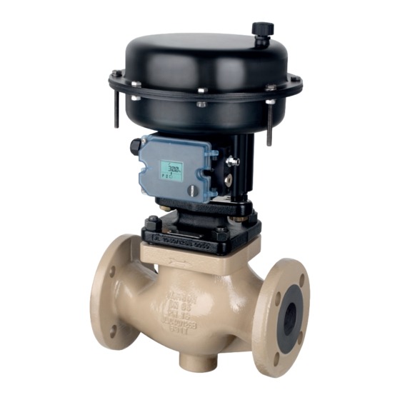
Page 17: Design And Principle Of Operation
(15). The Type 3321 Valve is a single-seated The process medium flows through the valve globe valve. This valve is preferably to be in the direction indicated by the arrow in the combined with the following SAMSON actu- flow-to-open direction. The plug position de- ators: termines the cross-sectional area between − Type 3371 Pneumatic Actuator the seat and plug. - Page 18 Design and principle of operation Fig. 3-2: Type 3321 Valve, DN 65 to 100/NPS 2½ to 4; mounting using rods (form C) Legend for Fig. 3-1 and Fig. 3-2 1 Body 14 Body nut A3/A7 Actuator stem 2 Valve bonnet 15 Packing A11/A33 Rod 4 Seat 17 Body gasket...
-
Page 19: Fail-Safe Action
Actuators of SAMSON actuators is specified on the ac- tuator nameplate. In these instructions, the preferable combina- Upon supply voltage failure, the Type 3374 tion with one of the following SAMSON ac- Electric Actuator (version with fail-safe action tuators is described. only) causes the valve to move to a certain − Type 5827 Electric Actuator fail-safe position. -
Page 20: Valve Accessories
ANSI/FCI 70-2) Information Sheet u T 8350 Noise emissions 3.5 Technical data SAMSON is unable to make general state- The nameplates on the valve and actuator ments about noise emissions. The noise emis- provide information on the control valve ver- sions depend on the valve version, plant fa- sion. - Page 21 Design and principle of operation Table 3-1: Dimensions and weights for Type 3321 Valve · DIN version Valve Dimension A H4 (with insulating section) Weight Weight (with insulating section) Table 3-2: Dimensions and weights for Type 3321 Valve · ANSI version ½...
- Page 22 Note Refer to the following data sheets for more dimensions and weights: u T 8111 and u T 8112 The associated actuator documentation applies to actuators, e.g. SAMSON actuators: u T 8313 for Type 3372 Electropneumatic Actuator u T 8317 for Type 3371 Pneumatic Actuator u T 5827 for Type 5827 Electric Actuator u T 8331 for Type 3374 Electric Actuator...
-
Page 23: Shipment And On-Site Transport
2. Check the shipment for transportation Î Stay clear of suspended or moving damage. Report any damage to loads. SAMSON and the forwarding agent Î Close off and secure the transport paths. (refer to delivery note). 3. Determine the weight and dimensions of WARNING... - Page 24 Shipment and on-site transport WARNING NOTICE Risk of personal injury due to the control Risk of valve damage due to incorrectly at- valve tipping over. tached slings. Î Observe the valve's center of gravity. Î When lifting the control valve, make sure Î...
-
Page 25: Transporting The Valve
Shipment and on-site transport 4.3.1 Transporting the valve ping off the hook during lifting and transporting. The control valve can be transported using − Secure slings against slipping. lifting equipment (e.g. crane or forklift). − Make sure the slings can be removed Î... -
Page 26: Storing The Valve
Elastomer, e.g. actuator diaphragm Î Avoid long storage times. − To keep elastomers in shape and to pre- Î Contact SAMSON in case of different vent cracking, do not bend them or hang storage conditions or longer storage them up. -
Page 27: Installation
Installation 5 Installation 5.1 Installation conditions The work described in this chapter is to be Work position performed only by personnel appropriately The work position for the control valve is the qualified to carry out such tasks. front view looking onto the operating con- trols (including valve accessories). Table 5-1: Inlet and outlet lengths Flow rate Inlet length... - Page 28 Valve accessories Î Observe the recommended inlet and outlet lengths (see Table 5-1). Contact Î During connection of valve accessories, SAMSON if the valve conditions or states make sure that they are easily accessible of the medium process deviate. and can be operated safely from the work position.
-
Page 29: Preparation For Installation
Installation 5.2 Preparation for installation Before installation, make sure the following conditions are met: − The valve is clean. − The valve and all valve accessories (in- cluding piping) are not damaged. − The valve data on the nameplate (type ... -
Page 30: Mounting The Device
Risk of valve damage due to the use of un- using a crossbeam (form B, Fig. 5-1), the ac- suitable tools. tuator is fastened to the valve bonnet using a Î Only use tools approved by SAMSON central nut. (u AB 0100). Table 5-2: Possible combinations and types of attachment Actuator Type of attachment... - Page 31 Installation Mounting using rods When the actuator is mounted using rods (form C, Fig. 5-2), the actuator is connected to the valve bonnet using rods. In this case, a crossbeam is not required for mounting the actuator. A plate keeps the correct distance between rods. b) Electric actuator When an electric actuator is mounted onto the valve, it is mounted with a form-fit con- nection using a stem connector and yoke.
- Page 32 Installation Fig. 5-1: Mounting using crossbeam and central nut (form B attachment) Type 3321-PP Type 3321-IP Type 3321-E1 Type 3321-E3 Fig. 5-2: Mounting using rods (form C attachment) Type 3321-PP Type 3321-IP Legend for Fig. 5-1 and Fig. 5-2 Central nut Crossbeam Plate EB 8111/8112 EN...
-
Page 33: Installing The Valve Into The Pipeline
5. Make sure that the correct flange gaskets Î SAMSON electric actuators are protect- ed against spray water. Avoid jets of wa- are used. ter. 6. Bolt the pipe to the valve free of stress. Î Observe all other safety instructions in 7. -
Page 34: Leakage
Installation WARNING WARNING WARNING Crush hazard arising from actuator and Risk of personal injury due to preloaded plug stem moving. springs in pneumatic actuators. Î Do not insert hands or finger into the Actuators with preloaded springs are under yoke while the air supply or voltage sup- tension. -
Page 35: Travel Motion
Installation 5.4.4 Pressure test 5. Check the valve for leakage to the atmo- sphere. The plant operator is responsible for per- 6. Depressurize the pipeline section and forming the pressure test. valve. 7. Rework any parts that leak and repeat the leak test. Our after-sales service can support you to plan and perform a pressure test for your 5.4.2 Travel motion plant. - Page 36 5-10 EB 8111/8112 EN...
-
Page 37: Start-Up
Start-up 6 Start-up WARNING WARNING The work described in this chapter is to be Crush hazard arising from actuator and performed only by personnel appropriately plug stem moving. qualified to carry out such tasks. Î Do not insert hands or finger into the yoke while the air supply or voltage sup- ply is connected to the actuator. - Page 38 Start-up Before start-up or putting the valve back into service, make sure the following conditions are met: − The control valve is properly installed in the pipeline (see the 'Installation' chap- ter). − The leak and function tests have been completed successfully (see the 'Testing the installed valve' chapter). −...
-
Page 39: Operation
Operation 7 Operation WARNING WARNING Immediately after completing start-up or put- Crush hazard arising from actuator and ting the valve back into operation, the valve plug stem moving. is ready for use. Î Do not insert hands or finger into the yoke while the air supply or voltage supply is connected to the actuator. - Page 40 EB 8111/8112 EN...
-
Page 41: Malfunctions
Malfunctions 8 Malfunctions Read hazard statements, warnings and caution notes in the 'Safety instructions and mea- sures' chapter. 8.1 Troubleshooting Malfunction Possible reasons Recommended action Actuator and plug stem Actuator is blocked. Put the control valve out of operation (see the does not move on 'Decommissioning' chapter) and remove the demand. -
Page 42: Emergency Action
Malfunctions Malfunction Possible reasons Recommended action Increased flow through Dirt or other foreign Shut off the section of the pipeline and flush the closed valve (seat particles deposited valve. leakage) between the seat and plug. Valve trim is worn out. Replace seat and plug (see the 'Servicing' chapter) or contact our after-sales service. The valve leaks to the Defective packing Replace packing (see the 'Servicing' chapter) or... -
Page 43: Servicing
Servicing 9 Servicing WARNING The work described in this chapter is to be Risk of burn injuries due to hot or cold com- performed only by personnel appropriately ponents and pipeline. qualified to carry out such tasks. Valve components and the pipeline may be- come very hot or cold. Risk of burn injuries. The following documents are also required Î... - Page 44 Risk of valve damage due to the use of un- Risk of personal injury due to preloaded suitable tools. springs in pneumatic actuators. Î Only use tools approved by SAMSON Actuators with preloaded springs are under (u AB 0100). tension. They can be identified by the long bolts protruding from the bottom of the actu- ator.
-
Page 45: Periodic Testing
Servicing Note The control valve was checked by SAMSON before delivery. − Certain test results certified by SAMSON lose their validity when the valve is opened. Such testing includes seat leakage and leak tests. − The product warranty becomes void if ser-... - Page 46 Servicing SAMSON recommends the following inspections and tests: Inspection and testing Recommended action to be taken in the event of a negative result Check the markings, labels and Immediately renew damaged, missing or incorrect nameplates on the valve for their nameplates or labels. readability and completeness.
-
Page 47: Service Work Preparations
Servicing 9.2 Service work preparations − Replace the packing (see Chapter 9.4.2) − Replace the seat and plug (see Chap- 1. Lay out the necessary material and tools ter 9.4.3) to have them ready for the service work. 2. Put the control valve out of operation (see 9.3 Installing the valve after the 'Decommissioning' chapter). -
Page 48: Service Work
Servicing 9.4 Service work b) For mounting using rods (form C) Î Before performing any service work, preparations must be made to the control 1. Undo the body nuts (14) gradually in a valve (see Chapter 9.2). crisscross pattern. Î After all service work is completed, check 2. Lift the valve bonnet (2) and plug with the control valve before putting it back plug stem (5) off the body (1). - Page 49 Servicing 1 Body 2 Valve bonnet 4 Seat 5 Plug (with plug stem) 8 Threaded bushing (packing nut) 13 Screw 14 Body nut 15 Packing Fig. 9-1: Form B attachment (mounting using a central nut) 17 Body gasket 96 Flange bonnet 97 Flange 98 Central nut A11 Rod A17 Crossbeam...
-
Page 50: Replacing The Packing
11. Press the plug (5) firmly into the seat (4), Note while fastening down the flange bonnet The Type 3321 Valve is either fitted with a (96) with the body nuts (14). Tighten the standard or form D packing. The packings nuts gradually in a crisscross pattern. have an identical design, but contain differ- Observe tightening torques. -
Page 51: Replacing The Seat And Plug
Observe tightening torques. Î Always replace both the seat and plug. When replacing the seat and plug, SAMSON also recommends replacing the gasket and packing (see Chapter 9.4.1 and Chapter 9.4.2). a) For mounting using cross- beam and central nut (form B) - Page 52 9. Apply a suitable lubricant to all the pack- 7. Unscrew the seat (4) using a suitable ing parts and to the new plug stem (5). tool. SAMSON recommends replacing the 8. Apply a suitable lubricant to the thread packing as well (see Chapter 9.4.2). and the sealing cone of the new seat.
-
Page 53: Ordering Spare Parts And Operating Supplies
Servicing 9.5 Ordering spare parts and operating supplies Contact your nearest SAMSON subsidiary or SAMSON's After-sales Service for infor- mation on spare parts, lubricants and tools. Spare parts See Appendix for details on spare parts. Lubricant See document u AB 0100 for details on suitable lubricants. Tools See document u AB 0100 for details on suitable tools. - Page 54 9-12 EB 8111/8112 EN...
-
Page 55: Decommissioning
Crush hazard arising from actuator and nection of the power supply. plug stem moving. Î SAMSON electric actuators are protect- Î Do not insert hands or finger into the ed against spray water. Avoid jets of wa- yoke while the air supply or voltage ter. - Page 56 Decommissioning Î Before working on the control valve, dis- To decommission the control valve for service connect and lock the pneumatic air sup- work or to remove it from the pipeline, pro- ply and the control signal or disconnect ceed as follows: the supply voltage and protect it against 1.
-
Page 57: Removal
Removal 11 Removal (e.g. spring compression). See associat- ed actuator documentation. The work described in this chapter is to be performed only by personnel appropriately qualified to carry out such tasks. WARNING WARNING Risk of personal injury due to residual pro- WARNING cess medium in the valve. Risk of burn injuries due to hot or cold com- While working on the valve, residual me- ponents and pipeline. -
Page 58: Removing The Valve From The Pipeline
Removal 11.1 Removing the valve from the pipeline 1. Support the valve to hold it in place when separated from the pipeline (see the 'Shipment and on-site transport' chapter). 2. Unbolt the flanged joint. 3. Remove the valve from the pipeline (see the 'Shipment and on-site transport' chapter). -
Page 59: Repairs
Î Do not perform any repair work on your ration on Decontamination) to the out- own. side of your shipment so that the docu- Î Contact SAMSON's After-sales Service ments are clearly visible. for service and repair work. 4. Send the shipment to the address given on the RMA. - Page 60 12-2 EB XXXX EN...
-
Page 61: Disposal
Disposal 13 Disposal SAMSON is a producer registered at the following European institution u https://www.ewrn.org/nation- al-registers/national-registers. WEEE reg. no.: DE 62194439/ FR 02566 Î Observe local, national and internation- al refuse regulations. Î Do not dispose of components, lubricants and hazardous substances together with your household waste. Note We can provide you with a recycling pass- port according to PAS 1049... - Page 62 13-2 EB 8111/8112 EN...
-
Page 63: Certificates
The certificates shown were up to date at the time of publishing. The latest certificates can These declarations are included on the next be found on our website: pages: u www.samsongroup.com > Products > − Declaration of conformity in compliance Valves > 3321 with Pressure Equipment Directive Other optional certificates are available on 2014/68/EU: request. − Country of origin: Germany, see page 14-2 to 14-4 − Country of origin: France, see page 14-5 to 14-8... - Page 64 Modul A/Module A SAMSON erklärt in alleiniger Verantwortung für folgende Produkte:/For the following products, SAMSON hereby declares under its sole responsibility: Geräte/Devices Bauart/Series Typ/Type Ausführung/Version DIN, Gehäuse GG, DN 65-125, Gehäuse GGG, DN 50-80, Fluide G2, L1, L2 Durchgangsventil/Globe valve...
- Page 65 EB 8111/8112 EN 14-3...
- Page 66 14-4 EB 8111/8112 EN...
- Page 67 DC014 Module A / Modul A 2022-05 Par la présente, SAMSON REGULATION SAS déclare sous sa seule responsabilité pour les produits suivants : For the following products, SAMSON REGULATION SAS hereby declares under its sole responsibility: Appareils / Exécution / Matériel du corps / body...
- Page 68 Modul A Normes techniques appliquées / Technical standards applied : DIN EN 12516-2, DIN EN 12516-3, ASME B16.34, DIN-EN 60534-4, DIN-EN 1092-1 Fabricant / manufacturer : Samson Régulation SAS, 1, rue Jean Corona, FR-69120 VAULX-EN-VELIN Vaulx-en-Velin, le 23/05/22 Bruno Soulas Joséphine Signoles-Fontaine...
- Page 69 Module H / Modul H, N°/ Nr CE-0062-PED-H-SAM 001-23-FRA 2023-06 Par la présente, SAMSON REGULATION SAS déclare sous sa seule responsabilité pour les produits suivants : For the following products, SAMSON REGULATION SAS hereby declares under its sole responsibility: Appareils / Exécution /...
- Page 70 The manufacturer’s quality management system is monitored by the following notified body: Bureau Veritas Services SAS N°/Nr 0062, 8 Cours du Triangle, 92800 PUTEAUX - LA DEFENSE Fabricant / manufacturer : Samson Régulation SAS, 1, rue Jean Corona, FR-69120 VAULX-EN-VELIN Vaulx-en-Velin, le 19/06/23 Bruno Soulas Joséphine Signoles-Fontaine...
- Page 71 EB 8111/8112 EN 14-9...
- Page 72 14-10 EB 8111/8112 EN...
- Page 73 EB 8111/8112 EN 14-11...
- Page 74 14-12 EB 8111/8112 EN...
- Page 75 Machinery components can be mounted onto the above specified final ma- chinery if they comply with the specifications and properties defined by SAMSON Manual H 02 “Ap- propriate Machinery Components for SAMSON Pneumatic Control Valves with a Declaration of Con- formity of Final Machinery”.
- Page 76 For the following product: Type 3321 Pneumatic Control Valve We certify that the Type 3321 Pneumatic Control Valves are partly completed machinery as defined in the in Directive 2008 No. 1597 Supply of Machinery (Safety) Regulations 2008 and that the safety requirements stip- ulated in Annex I, 1.1.2, 1.1.3, 1.1.5, 1.3.2, 1.3.4 and 1.3.7 are observed.
- Page 77 Operating temperature: -29° C ≤ T ≤425° C. SAMSON REGULATION S.A. SAMSON REGULATION S.A. Bruno Soulas Joséphine Signoles-Fontaine Head of Administration QSE Manager SAMSON REGULATION S.A. · 1, rue Jean Corona · 69511 Vaulx-en-Velin, France · samson@samson.fr EB 8111/8112 EN 14-15...
- Page 78 14-16 EB 8111/8112 EN...
-
Page 79: Appendix
Appendix 15 Appendix 15.1 Tightening torques, lubri- cants and tools u AB 0100 for tools, tightening torques and lubricants 15.2 Spare parts Body Bonnet (including guide bushing) Seat Plug (with plug stem) Threaded bushing (packing nut) Spring Washer Stud bolt Body nut Packing V-ring packing Body gasket Spacer Flow divider ST 1 Tension ring 1) Flange bonnet (including guide bushing) Flange... - Page 80 Appendix Type 3321 · DN 15 to 50/NPS ½ to 2 15-2 EB 8111/8112 EN...
- Page 81 Appendix Type 3321 · DN 65 to 100/NPS 2½ to 4 EB 8111/8112 EN 15-3...
-
Page 82: After-Sales Service
(Safety) Regulations 2016, STATUTORY E-mail address INSTRUMENTS, 2016 No. 1105 (UKCA You can reach our after-sales service at marking). It does not apply to Northern Ire- aftersalesservice@samsongroup.com. land. Addresses of SAMSON AG and its subsid- Importer iaries SAMSON Controls Ltd The addresses of SAMSON AG, its subsid- Perrywood Business Park iaries, representatives and service facilities... - Page 84 EB 8111/8112 EN SAMSON AKTIENGESELLSCHAFT Weismüllerstraße 3 · 60314 Frankfurt am Main, Germany Phone: +49 69 4009-0 · Fax: +49 69 4009-1507 samson@samsongroup.com · www.samsongroup.com...
Need help?
Do you have a question about the 3321 and is the answer not in the manual?
Questions and answers