Table of Contents
Advertisement
Available languages
Available languages
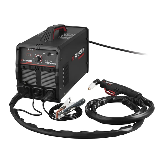
PLASMASCHNEIDER MIT KOMPRESSOR PPSK 40 B2
PLASMA CUTTER WITH INTEGRATED COMPRESSOR PPSK 40 B2
DE
PLASMASCHNEIDER
MIT KOMPRESSOR
Bedienungs- und Sicherheitshinweise
Originalbetriebsanleitung
GB
PLASMA CUTTER WITH
INTEGRATED COMPRESSOR
Operation and Safety Notes
Translation of the original instructions
IAN 418546_2210
DE
Advertisement
Chapters
Table of Contents

Related Manuals for Parkside PPSK 40 B2


Summary of Contents for Parkside PPSK 40 B2
- Page 1 PLASMASCHNEIDER MIT KOMPRESSOR PPSK 40 B2 PLASMA CUTTER WITH INTEGRATED COMPRESSOR PPSK 40 B2 PLASMASCHNEIDER MIT KOMPRESSOR Bedienungs- und Sicherheitshinweise Originalbetriebsanleitung PLASMA CUTTER WITH INTEGRATED COMPRESSOR Operation and Safety Notes Translation of the original instructions IAN 418546_2210...
- Page 2 Klappen Sie vor dem Lesen die beiden Seiten mit den Abbildungen aus und machen Sie sich anschließend mit allen Funktionen des Gerätes vertraut. Before reading, unfold the page containing the illustrations and familiarise yourself with all functions of the device. Montage-, Bedienungs- und Sicherheitshinweise Seite Operation and Safety Notes...
-
Page 5: Table Of Contents
Tabelle der verwendeten Piktogramme ..............Seite Einleitung ........................Seite Bestimmungsgemäße Verwendung ................Seite Lieferumfang ......................Seite Teilebeschreibung ......................Seite Technische Daten .......................Seite Sicherheitshinweise ....................Seite Allgemeine Plasma-Erläuterungen .................Seite Vor der Inbetriebnahme ..................Seite Aufstellungsumgebung ....................Seite Auswahl Druckluftversorgung ..................Seite Vorgehen bei Verwendung eines externen Kompressors ..........Seite Anschluss des Schneidbrenners ...................Seite Massekabel anschließen .....................Seite Montage der abnehmbaren Rollenführung (optional) ............Seite Inbetriebnahme ......................Seite... -
Page 6: Tabelle Der Verwendeten Piktogramme
z Tabelle der verwendeten Piktogramme Verwenden Sie das Gerät nicht Achtung! Betriebsanleitung lesen! im Freien und nie bei Regen! Das nebenstehende Symbol einer durchgestrichenen Müll- Achtung, mögliche Gefahren! tonne auf Rädern zeigt, dass dieses Gerät der Richtlinie 2012/19/EU unterliegt. Hergestellt aus Vorsicht! Stromschlaggefahr! Recyclingmaterial. -
Page 7: Einleitung
Plasmaschneider mit Kompressor PPSK 40 B2 z Einleitung Herzlichen Glückwunsch! Sie haben sich für ein hochwertiges Gerät aus unserem Haus entschieden. Machen Sie sich vor der ersten Inbetriebnahme mit dem Produkt vertraut. Lesen Sie hierzu aufmerksam die nachfolgende Bedienungsanleitung und die Sicherheits- hinweise. -
Page 8: Lieferumfang
Vermindern Sie das Restrisiko, indem Sie das Gerät sorgfältig und vorschriftsmäßig benutzen und alle Anweisungen befolgen. z Lieferumfang 1 Plasmaschneider mit Kompressor 1 Massekabel mit Klemme 1 Schneidkabel inkl. Schneidbrenner 3 Elektroden (1 vormontiert) 1 Bedienungsanleitung 3 Brennerhüllen (1 vormontiert) 1 Abnehmbare Rollenführung 1 Druckluftschlauch z Teilebeschreibung... -
Page 9: Technische Daten
Fixierschrauben Druckluftschlauch Führungsrollen Schutzkappe z Technische Daten Leistung: 15 - 40 A Eingang: 230 V~ 50 Hz Abmessungen: 396 x 200 x 245 mm Isolationsklasse: Schnittleistung: 0,1 mm - 12 mm (je nach Material) Kupfer: 1 - 4 mm Edelstahl: 1 - 8 mm Aluminium: 1 - 8 mm Eisen: 1 - 10 mm Stahl: 1 - 12 mm... - Page 10 Dieses Gerät kann von Kindern ab 16 Jahren und darüber sowie „ von Personen mit verringerten physischen, sensorischen oder men- talen Fähigkeiten oder Mangel an Erfahrung und Wissen benutzt werden, wenn sie beaufsichtigt oder bezüglich des sicheren Ge- brauchs des Gerätes unterwiesen wurden und die daraus resul- tierenden Gefahren verstehen.
- Page 11 Seien Sie sich bewusst, dass das Schneiden an einer Decke, am „ Boden oder einem Teilbereich ein Feuer auf der gegenüberliegen- den, nicht sichtbaren Seite, verursachen kann. Verbinden Sie das Stromkabel, auf kürzestem Wege, mit einer in „ der Nähe des Arbeitsplatzes liegenden Steckdose, um zu vermei- den, dass das Stromkabel im ganzen Raum ausgebreitet ist und sich auf einem Untergrund befinden könnte, der einen elektrischen Schock, Funken und Feuerausbruch verursachen kann.
- Page 12 GEFÄHRDUNG DURCH FUNKENFLUG BEIM PLASMASCHNEIDEN: Schneidfunken können eine Explosion oder einen Brand verursa- „ chen. Brennbare Stoffe vom Schneiden fernhalten. „ Nicht neben brennbaren Stoffen plasmaschneiden. „ Schneidfunken können Brände verursachen. „ Einen Feuerlöscher in der Nähe bereithalten und einen Beobachter, „...
- Page 13 den vertraut. Beachten Sie hierzu auch die Sicherheits hinweise Ihres Plasmaschneiders. Setzen Sie den Schweißschirm immer beim Schweißen und Plasma- „ schneiden auf. Bei Nichtverwendung können Sie sich schwere Netz- hautverletzungen zuziehen. Tragen Sie während des Schweißens und Plasmaschneidens immer „...
- Page 14 zu bestimmen, welche Schritte notwendig sind, um die Sicherheit der Arbeit sicherzustellen und welche Vorsichtsmaßnahmen während des eigentlichen Schneidvorgangs getroffen werden sollten. z Summierung der Leerlaufspannungen Wenn mehr als eine Plasmastromquelle gleichzeitig in Betrieb ist, kön- nen sich deren Leerlaufspannungen summieren und zu einer erhöhten elektrischen Gefährdung führen.
- Page 15 wenn nötig, auch ein Kopfschutz zu tragen. z Schutz gegen Strahlen und Verbrennungen An der Arbeitsstelle durch einen Aushang „Vorsicht! Nicht in die „ Flammen sehen!“ auf die Gefährdung der Augen hinweisen. Die Arbeitsplätze sind möglichst so abzuschirmen, dass in der Nähe befindliche Personen geschützt sind.
-
Page 16: Allgemeine Plasma-Erläuterungen
die Tageszeit, zu der die Schneidarbeiten durchgeführt werden. – Um mögliche Störstrahlungen zu verringern, wird empfohlen: den Plasmaschneider regelmäßig zu warten und in einem guten – Pflegezustand zu halten. Schneidleitungen sollten vollständig abgewickelt werden und – möglichst parallel auf dem Boden verlaufen durch Störstrahlung gefährdete Geräte und Anlagen sollten –... -
Page 17: Vorgehen Bei Verwendung Eines Externen Kompressors
Bei Verwendung des integrierten Kompressors stellen Sie den Umschalter externe Druckluft „ Position „zu“ (Abbildung L). z Vorgehen bei Verwendung eines externen Kompressors HINWEIS: Zum Plasmaschneiden wird ein Druck von 4-4,5 Bar empfohlen. Stellen Sie dies an ihrem Kompressor entsprechend ein. Bedenken Sie bitte, dass der Druck beim Einstellen des Luftdrucks absinken kann. -
Page 18: Überhitzungsschutz- Und Hrd-Anzeige
Stellen Sie den Plasmaschneider an einem trockenen und gut belüfteten Ort auf. Platzieren Sie die Maschine in der Nähe des Werkstücks. Klemmen Sie die Masseklemme an das zu schneidende Werkstück und stellen Sie sicher, dass ein guter elektrischer Kontakt besteht. Drücken Sie den Ein / Aus - Schalter Stellen Sie am Stromregler den Schneidstrom ein. -
Page 19: Fehlerbehebung
Plasmabrenner gerade so schnell, dass sich die Funkenansammlung an der Unterseite des Arbeits- gegenstandes konzentriert. Vergewissern Sie sich, dass das Material komplett durchtrennt ist, bevor Sie fortfahren. Stellen Sie die Drag-Geschwindigkeit wie erforderlich ein. Distanzschneiden In einigen Fällen ist es vorteilhaft, mit der Brennerhülle die ca. - Page 20 Ausgangsstrom verringert sich? Eingangsspannung zu nied- Eingangsspannung laut Ty- „ „ rig. penschild beachten. Anschlußkabel Querschnitt „ zu gering. Bogen stoppt während des Schneidegeschwindigkeit ist Erhöhen Sie die Schneide- „ „ Schneidens? zu gering. geschwindigkeit bis das Plasmabrenner wird zu Problem nicht mehr vorhan- „...
-
Page 21: Wartung Und Reinigung
Funken schießen nach oben, Der Plasmastrahl durch- Erhöhen Sie die Stromstär- „ „ anstatt nach unten durch das dringt nicht das Material. Material? Brennerhülle zu weit Verringern Sie den Abstand „ „ entfernt vom Material. von der Brennerhülle Material wurde vermutlich Material. -
Page 22: Wartung
ACHTUNG: Zum Herausziehen der Elektrode die Kraft nicht ruckweise aufwenden, sondern all- mählich erhöhen, bis sich die Elektrode löst. Die neue Elektrode wird nun in ihre Aufnahme gesteckt. Die Brennerhülle ist auszutauschen, wenn die Mittelbohrung beschädigt ist oder sich im Vergleich zur Bohrung einer neuen Düse erweitert hat. -
Page 23: Eu-Konformitätserklärung
Wir, die C. M. C. GmbH Dokumentenverantwortlicher: Dr. Christian Weyler Katharina-Loth-Str. 15 DE-66386 St. Ingbert DEUTSCHLAND erklären in alleiniger Verantwortung, dass das Produkt Plasmaschneider mit Kompressor PPSK 40 B2 418546_2210 IAN: 2586 Art. - Nr.: 2023/32 Herstellungsjahr: PPSK 40 B2 Modell: den wesentlichen Schutzanforderungen genügt, die in den Europäischen Richtlinien... -
Page 24: Hinweise Zu Garantie Und Serviceabwicklung
EN 60974-6:2016 EN 60974-10:2014 + A1:2015 EN 1012-1:2010 EN ISO 12100:2010 St. Ingbert, 01.01.2023 Dr. Christian Weyler - Qualitätssicherung - z Hinweise zu Garantie und Serviceabwicklung Garantie der Creative Marketing & Consulting GmbH Sehr geehrte Kundin, sehr geehrter Kunde, Sie erhalten auf dieses Gerät 5 Jahre Garantie ab Kauf- datum. -
Page 25: Abwicklung Im Garantiefall
autorisierten Service-Niederlassung vorgenommen wurden, erlischt die Garantie. z Abwicklung im Garantiefall Um eine schnelle Bearbeitung Ihres Anliegens zu gewährleisten, folgen Sie bitte den folgenden Hinwei- sen: Bitte halten Sie für alle Anfragen den Kassenbon und die Artikelnummer (z. B. IAN) als Nachweis für den Kauf bereit. - Page 26 Table of pictograms used ..................Page Introduction ......................Page Intended use ......................Page Scope of delivery.......................Page Parts description ......................Page Technical Specifications ....................Page Safety instructions ....................Page General plasma explanations ................Page Before use .........................Page Installation environment ....................Page Selecting compressed air supply ..................Page Procedure when using an external compressor ..............Page Connecting the cutting burner ..................Page Connecting the earthing cable ..................Page Fitting the removable roller guide (optional) ..............Page...
-
Page 27: Table Of Pictograms Used
z Table of pictograms used Attention! Never use the device in the Read the operating instructions! open air or when it’s raining! The adjacent symbol of a crossed-out dustbin on the Attention: possible risks! wheels indicates that this device is subject to the 2012/19/EU directive. -
Page 28: Introduction
Plasma cutter with integrated compressor PPSK 40 B2 z Introduction Congratulations! You have purchased one of our high-quality devices. Please familiarise yourself with the product before using it for the first time. To do this, please read through the following operating and safety instructions carefully. This tool must be set up or used only by people who have been trained to do so. -
Page 29: Parts Description
1 earthing cable with terminal 1 cutting cable incl. cutting burner 3 electrodes (1 pre-assembled) 1 set of operating instructions 3 burner sleeves (1 pre-mounted) 1 removable roller guide 1 compressed air hose z Parts description PLEASE NOTE: After unpacking the product, please check that all of the package contents are present and that the device is in perfect condition. -
Page 30: Technical Specifications
z Technical Specifications Output: 15–40 A Input: 230 V~ 50 Hz Dimensions: 396 × 200 x 245 cm Insulation class: Cutting performance: 0.1 mm – 12 mm (depending on the material) Copper: 1–4 mm Stainless steel: 1–8 mm Aluminium: 1–8 mm Iron: 1–10 mm Steel: 1–12 mm Working pressure: 4–4.5 bar... - Page 31 children to play with the device. Cleaning and day-to-day mainte- nance must not be performed by children without supervision. Repairs and/or maintenance work must only be carried out by „ qualified electricians. Only use the cutting cable provided in the scope of delivery. „...
- Page 32 Do not touch the electrodes with bare hands. „ Do not wear wet or damaged gloves. „ Protect yourself from electric shock with insulation against the „ workpiece. Do not open the device housing. „ Additional protection against a shock from the mains power in „...
- Page 33 Cutting current generates electromagnetic fields. „ Do not use if you have a medical implant. „ Never wrap the cutting cable around your body. „ Guide cutting cables together. „ z Welding mask-specific safety instructions With the help of a bright light source (e.g. lighter) examine the „...
- Page 34 When using plasma cutters under electrically dangerous conditions, the output voltage of the plasma cutter must not be greater than 113 V when idling (peak value). The plasma cutter may not be used in these cases due to the output voltage. z Plasma cutting in tight spaces When welding and plasma cutting in tight spaces this may pose a hazard through toxic gases (risk of suffocation).
- Page 35 Gauntlet gloves made of a suitable material (leather) must be worn „ on both hands. They must be in perfect condition. A suitable apron must be worn to protect clothing from flying „ sparks and burns. When specific work, e.g. overhead cutting, is required, a protective suit must be worn and, if necessary, even head protection.
-
Page 36: General Plasma Explanations
noise immunity of other devices in the vicinity – the time of day at which the cutting work is performed. – The following is recommended to reduce possible interference radiation: the plasma cutter must be regularly maintained and kept in –... -
Page 37: Procedure When Using An External Compressor
z Procedure when using an external compressor PLEASE NOTE: For plasma cutting, a pressure of 4–4.5 bar is recommended. Adjust this accord- ingly on your compressor. Please bear in mind that the pressure can lower while setting the air pressure. Thus, in a hose length measuring 10 m and an internal diameter of 9 mm it drops by approx. -
Page 38: Overheating Protection And Hrd Display
must be set higher if necessary. If the electrode burns through frequently, then the cutting current must be set lower. Position the plasma cutter on the workpiece so that the burner sleeve is free and that a blowback of the molten metal is not possible. Push the interlocking switch forwards to lock the plasma burner button in place. -
Page 39: Troubleshooting
form. Test the perforation on a test object that is no longer needed and once there are no problems start drilling through at the previously defined cutting line on your workpiece. Check the plasma burner for wear and tear, cracks or exposed cable pieces. Replace or repair them prior to using the device. A badly worn burner sleeve contributes to the reduction of speed, voltage and unclean separation. - Page 40 HF-arc is not created? The burner switch is faulty. Replace electrode. „ „ Soldering point on the burner „ switch or plug loosened. Valve/manometer fails. „ Bad ignition? Burner wear parts damaged Change wear parts. „ „ or worn. Current switch is Switch the current switch „...
-
Page 41: Maintenance And Cleaning
z Maintenance and cleaning z Maintaining the burner Switch off the main power supply and the main switch of the device prior to carrying out maintenance or repair work on the plasma cutter. The consumables displayed in Figure F are the electrode , diffuser and the burner sleeve „... -
Page 42: Ec Declaration Of Conformity
C. M. C. GmbH Responsible for documentation: Dr. Christian Weyler Katharina-Loth-Str. 15 66386 St. Ingbert GERMANY hereby take sole responsibility for declaring that the product Plasma cutter with integrated compressor PPSK 40 B2 418546_2210 IAN: 2586 Art. no.: 2023/32 Year of manufacture:... -
Page 43: Warranty And Service Information
and the amendments to these Directives. The object of the declaration described above meets the requirements of Directive 2011/65/EU of the European Parliament and of the Council of 8 June 2011 on the restriction of the use of certain hazardous substances in electrical and electronic equipment. This conformity assessment is based on the following harmonised standards: EN 60974-6:2016 EN 60974-10:2014 + A1:2015... -
Page 44: Processing Of Warranty Claims
This warranty is voided if the product becomes damaged or is improperly used or maintained. For proper use of the product, all of the instructions given in the operating instructions must be followed precisely. If the operating instructions advise you or warn you against certain uses or actions, these must be avoided in all circumstances. - Page 45 C.M.C. GmbH Katharina-Loth-Str. 15 DE-66386 St. Ingbert GERMANY Stand der Informationen · Last Information Update: 01/2023 Ident.-No.: PPSK40B2012023-10 IAN 418546_2210...
Need help?
Do you have a question about the PPSK 40 B2 and is the answer not in the manual?
Questions and answers