Advertisement
IP 9519-1 EN (100050753)
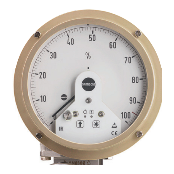
Media 5 · Option module with 4 to 20 mA current output
Firmware version 1.02
These instructions supplement the mounting and operating instructions EB 9519, which con-
tains detailed information on the Media 5 Differential Pressure and Flow Meter.
1 Nameplate
A self-adhesive nameplate is in-
cluded in the retrofi t kit for the
option module. It must be affi xed
to the indicating unit after the
option module is installed. A
nameplate is already affi xed
when the option module is al-
ready installed upon delivery.
1 Firmware version
2 Material number
3 Serial number
4 QR code to go to
product documentation
Edition September 2020
Current output option module installed in the indicating unit
Nameplate of version without explosion protection:
I
OUT
Firmware
Material
SAMSON AG, Germany
Nameplate of version with explosion protection:
I
OUT
Ex ia IIC T4 Gb
IECEx KIWA 19.0013X
U ≤ 28 V DC; I ≤ 115 mA; P ≤ 1.0 W; C ≈ 10 nF; L ≈ 0 mH
i
Material
SAMSON AG, Germany
5005-0
Module
= 4 to 20 mA, U = 12 to 36 V DC
IN
WARNING - POTENTIAL ELECTROSTATIC
CHARGING HAZARD - SEE INSTRUCTIONS
1
Serial no.
2
5005-3
= 4 to 20 mA, U = 12 to 28 VDC
IN
II 2 G Ex ia IIC T4 Gb
KIWA 19 ATEX 0023 X
i
i
i
WARNING - POTENTIAL ELECTROSTATIC CHARGING HAZARD
SEE INSTRUCTIONS
Serial no.
2
3
0044
i
-20 °C ≤ Ta ≤ +70 °C
Firmware
3
1
4
Made in Germany
4
Made in Germany
Advertisement
Table of Contents

Related Manuals for Samson Media 5


Summary of Contents for Samson Media 5
- Page 1 Firmware nameplate is already affi xed Material Serial no. when the option module is al- SAMSON AG, Germany Made in Germany ready installed upon delivery. Nameplate of version with explosion protection: 5005-3 = 4 to 20 mA, U = 12 to 28 VDC...
-
Page 2: Design And Principle Of Operation
cate is exceeded, even when only briefl y. To continue operation of the option module in hazardous areas in such cases, SAMSON or a person with the corresponding qualifi cations must Nameplate (label) provide eviden that all safety/ protection features within the device Printed circuit board with operating controls or module are fully effective. -
Page 3: Technical Data
Design and principle of operation The following applies to the version without explosion protection (100033844): − Use of the option module in hazardous areas is not permissible. 2.1 Technical data 4 to 20 mA current output Module 100049064 Module 100033844 with explosion protection without explosion protection 1) Version Magnetoresistive measuring system Supply voltage U... -
Page 4: Installation
Installation 3 Installation 1. Undo the four housing screws. Remove the housing cover. 2. Unscrew the two dial plate screws and DANGER remove the cover plate. Retighten dial Risk of fatal injury due to the ignition of an plate screws. explosive atmosphere. - Page 5 Installation 5. Slide the mating plate underneath the pointer and magnetoresistive measuring system to fasten the elements together. Make sure it fi ts properly. Pay attention Connector to the counterweight at the end of the pointer. Magnetoresistive measur- ing system with mating plate Pointer in zero position with attached...
- Page 6 Installation 9. Insert the terminal board at the side un- The option module consists of an actively derneath the dial plate. controlled current loop with a 4 to 20 mA loop current. This current depends on the Use Phillips screwdriver to tighten the position of the pointer on the Media 5 retaining screw.
- Page 7 Installation 3.1 Settings Level Blinking pattern Zero calibration The option module has a green LED (1) and Span calibration a red LED (2) as well as a key (3) and key (4) to perform settings. Characteristic 4 mA/20 mA ammeter Zero calibration The electric zero is adapted to the mechani- cal zero.
- Page 8 Installation A measuring span calibration is possible in Activate characteristic level the pointer range >95° (based on the point- Function er's zero point, see Fig. 12). 3x key Green Blinking pattern The red LED is permanently lit (error indica- The blinking pattern indicates tion) if the calibration range is exceeded.
-
Page 9: Servicing Explosion-Protected Devices
The option module returns to standard explosion-protected devices. operation. – Use the protective cable designed by SAMSON when interconnecting non- intrinsically safe set point calibrators 4 Servicing explosion-protected with intrinsically safe equipment for repair, calibration etc. to ensure that devices components relevant to explosion Î... - Page 10 IP 9519-1 EN SAMSON AKTIENGESELLSCHAFT Weismüllerstraße 3 · 60314 Frankfurt am Main, Germany Phone: +49 69 4009-0 · Fax: +49 69 4009-1507 samson@samsongroup.com · www.samsongroup.com...
Need help?
Do you have a question about the Media 5 and is the answer not in the manual?
Questions and answers