
Related Manuals for Defibtech RMU-2000


Summary of Contents for Defibtech RMU-2000
- Page 1 Defibtech RMU-2000 Automated Chest Compression System User Manual ELECTRONIC DISTRIBUTION RAC-A2510EN-DC rev B...
- Page 3 Notices Defibtech, L.L.C. shall not be liable for errors contained herein or for incidental or consequential damages in connection with the furnishing, performance, or use of this material. Information in this document is subject to change without notice. Names and data used in the examples are fictitious unless otherwise noted.
-
Page 4: Table Of Contents
Contents Introduction to the RMU-2000 ACC ....... . . 7 Overview . - Page 5 RMU-2000 ACC Accessories ........
- Page 6 This page intentionally left blank. RAC-A2510EN-DC rev B...
-
Page 7: Introduction To The Rmu-2000 Acc
The RMU-2000 ACC, when applied to a patient who is unconscious and not breathing, is designed to: • Provide consistent depth and rate chest compressions. -
Page 8: The Defibtech Rmu-2000 Acc
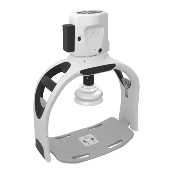
1.2 The Defibtech RMU-2000 ACC RAC-A2510EN-DC rev B... - Page 9 1. User Control Panel. The User Control 8. Stabilization Strap. The Stabilization Panel contains the user interface for the Strap is used to stabilize the RMU-2000 RMU-2000 ACC system. ACC while compressions are being applied by the unit to the patient. To 2.
-
Page 10: Indications For Use / Intended Use
The RMU-2000 ACC must only be used in cases where chest compressions are likely to help the patient. -
Page 11: Operator Training Requirements
1.6 Operator Training Requirements In order to safely and effectively operate the RMU-2000 ACC, it is the responsibility of the operator to obtain the following training: • RMU-2000 ACC training in accordance with the User Manual including handling of the actual device •... - Page 12 This page intentionally left blank. RAC-A2510EN-DC rev B...
-
Page 13: Warnings And Cautions
• If the patient is too large for the Frame, remove Frame and continue manual CPR compressions. • Do not use the RMU-2000 ACC if the Frame cannot be latched in place (for any reason). • Keep clothing and other objects from interfering with the Frame latching mechanism when connecting to the Backboard. - Page 14 Replace the Battery Pack as soon as possible with a sufficiently-charged Battery Pack or apply external power. • If a spare Battery Pack or external power source are not available and the RMU-2000 ACC stops compressions, remove the unit from the patient and begin manual compressions immediately.
-
Page 15: Cautions
(such as bag-valve-mask devices or ventilator tubing). Turn off gas source or move away from patient, if necessary. • Do not position the RMU-2000 ACC in a way that would cause difficulty to the operator to disconnect it from the power source. - Page 16 RMU-2000 ACC. Using other accessories can cause permanent damage and void the warranty. • The RMU-2000 ACC must be paused in order to replace a Battery Pack. Failure to do so will require the user to power up the RMU-2000 ACC and reset the start position in order to resume compressions.
-
Page 17: Setting Up The Rmu-2000 Acc
This chapter describes the steps required to make your Defi btech RMU-2000 ACC operational. The RMU-2000 ACC is designed to be stored in a Carrying Case with a small number of easy to assemble components or stored in a fully assembled “ready” state. This chapter explains how to set up the RMU-2000 ACC device. -
Page 18: Complete Initial Assembly Of The Rmu-2000 Acc
RMU-2000 ACC system and their basic functionality. 3.3 The Backboard The Backboard is the base for the RMU-2000 ACC system. It is placed under the patient and has pins that serve as attachment points to which the Frame latches. There are no moving parts on the Backboard. -
Page 19: Installing The Suction Cup Onto The Frame
Cup snaps into place, as shown below. Note: Defibtech recommends that the Suction Cup be installed to onto the Frame prior to a rescue and that the Frame be stored in the Carrying Case with the Suction Cup already attached to the Frame. -
Page 20: The Compression Module
3.6 The Compression Module The Compression Module contains all the active components of the RMU-2000 ACC system, including the User Control Panel, the Battery Pack and the Compression Piston. It easily attaches to the Frame and locks into place for operation. -
Page 21: Installing And Removing The Compression Module And Suction Cup
3.7 Installing and Removing the Compression Module and Suction Cup To attach the Compression Module to the Frame, power the Compression Module on and insert it into the module receptacle of the Frame, as shown below. The Module should be inserted at approximately 90 degrees to the Frame at which point it should rest in the Frame. -
Page 22: Attaching The Patient Wrist Straps To The Frame
Strap Loop The Patient Wrist Straps are designed to attach a patient’s arms to the RMU-2000 ACC for ease of transporting the patient and the RMU-2000 ACC. As shown in the above left illustration, each Patient Wrist Strap is comprised of two main strap sections: a Frame Strap that attaches to the Frame and a Forearm Strap that wraps around the patient’s wrist. - Page 23 Attaching the Patient Wrist Straps to the Frame (continued) To maximize the available time to perform a rescue, Defi btech recommends that the Patient Wrist Straps be affi xed to the Frame using the instructions shown below prior to a rescue and that the Frame be stored in the Carrying Case with the Patient Wrist Straps already attached to the Frame.
-
Page 24: Attaching The Stabilization Strap Frame Straps To The Frame
Main Strap that gets situated on the underside of the patient’s neck during a rescue and two Frame Straps that attach to the RMU-2000 ACC’s frame. Buckle connectors allow for easy attachment of the Frame Straps to the Frame (procedure described below) and of the Main Strap to the Frame Straps (see Section 4.4, “Stabilization”). -
Page 25: Installing And Removing The Battery Pack
Pack all the way in until the latch clicks. The Battery Pack will operate in either orientation (with the contacts toward the unit). When the Battery Pack is inserted, the RMU-2000 ACC will display the status of the Battery Pack on the Compression Module’s Battery Pack indicator for approximately three seconds. -
Page 26: Charging The Battery Pack
Battery Pack Charging Station (see Section 6.7 for details). To connect the AC Adapter to the RMU-2000 ACC, insert the AC adapter plug into the Compression Module's external power input jack as shown in the center illustration above. As the jack is keyed, the raised notch on the plug must align with the notch on the jack in order for the plug to seat properly and lock into place. - Page 27 Charging the Battery Pack (continued) Battery Pack Indications and Alarms (on User Control Panel) LED Indications Visual Indication Description Action Battery Pack charge is All green None >80% Number of bars show Partial green percent of Battery Pack None (if possible, charge to full capacity) charge (20% per bar) If performing a rescue, replace Battery Pack Battery Pack low...
-
Page 28: Assembling And Testing The Rmu-2000 Acc
Battery Pack Indications (on Battery Pack) To check the charge of a Battery Pack while it is not installed in the RMU-2000 ACC, press the button on the bottom of the Battery Pack for about a second. The Battery Pack charge indicator will show the amount of remaining charge: <5%... -
Page 29: Disassembling And Storing The Rmu-2000 Acc
Use the following steps to disassemble and store the unit in the case: • Remove the Suction Cup from the RMU-2000 ACC by grabbing the edges of the Suction Cup's circular connector ring and pulling down fi rmly (see Section 3.7 for details and illustrations). -
Page 30: Checking And Charging The Battery Pack While In The Carrying Case
3.14 Checking and Charging the Battery Pack While in the Carrying Case If the Compression Module is stored in the Carrying Case with a Battery Pack installed, the charge level of the Battery Pack can be checked by briefl y pressing the Power ON/OFF button through the viewing window located on the underside of the case, as shown here: Battery Pack Indicators (on Compression Module’s... -
Page 31: Using The Rmu-2000 Acc
The following sections describe in detail how to use the RMU-2000 ACC. The basic steps for use are: • Place Backboard under patient and expose chest. - Page 32 RMU-2000 ACC will not be powered on); press and hold the Power ON/OFF button for at least one second to turn the RMU-2000 ACC off. LED indicators adjacent to the Adjust Up/Down Buttons illuminate and blink when the RMU-2000 ACC is requesting that the piston be adjusted to the patient’s chest.
-
Page 33: Arrival And Setup
4.2 Arrival and Setup This section details the steps required to use the RMU-2000 ACC during an emergency. Based on performance testing, the expected deployment time* is approximately 45 seconds and may be less for experienced trained users. - Page 34 Arrival and Setup (continued) STEP 3) Place the Backboard under patient just below armpits. Lift patient body slightly and slide the Backboard under patient or roll patient from side to side, as needed. The center of the Backboard should be in line with the nipple line of the patient. Accurate placement of the Backboard will help with the alignment step later.
- Page 35 If the Battery Pack indicator shows red (low battery), or the RMU-2000 ACC does not turn on, replace the Battery Pack or connect external power (see Section 4.7 “Power“ for details).
- Page 36 STEP 10) Pull up on the Frame and Compression Module assembly to make sure that Frame is securely latched to the Backboard. If patient is too large for the Frame, remove Frame and continue manual CPR compressions. Do not use the RMU-2000 ACC if the Frame cannot be latched to the Backboard. WARNING...
- Page 37 Do not initiate automated chest compressions if a Suction Cup is not attached to the end of the Piston as doing so may result in patient injury. If a Suction Cup is not available, discontinue use of the RMU-2000 ACC and continue WARNING performing manual chest compressions.
-
Page 38: Operation And Adjustment
Breaths button: Run Continuous Run with Breaths When compressions are initiated, the RMU-2000 ACC gradually reaches full compression depth during the fi rst few seconds of operation by having the initial compressions be of shorter yet incrementally increasing depths. To temporarily stop compressions for any reason, press the pause button. If necessary, make adjustments to the Suction Cup position using the Adjust Up/Down Buttons so that it is making fi rm contact with the patient’s chest. - Page 39 This behavior is normal. Note: If there are no user actions after the RMU-2000 ACC is powered on and the device is not performing compressions, the Compression Module will automatically power itself off after 10 continuous minutes of inactivity have elapsed.
-
Page 40: Stabilization
Stabilization Strap to the Frame using the procedure that follows. Note: To maximize the available time to perform a rescue, Defibtech recommends that the Stabilization Strap’s Frame Straps be affixed to the Frame using the instructions shown in Section 3.9 prior to a rescue and that the Frame be stored in the Carrying Case with the Stabilization... - Page 41 Stabilization Strap and readjust as instructed above. Note: As with any step in using the RMU-2000 ACC, it is important to minimize the time CPR is not being performed. If the RMU-2000 ACC is not performing compressions for any reason, always consider performing manual CPR.
-
Page 42: Securing The Patient Wrist Straps To The Patient
4.5 Securing the Patient Wrist Straps to the Patient Note: To maximize the available time to perform a rescue, Defi btech recommends that the Patient Wrist Straps be affi xed to the Frame using the instructions shown in Section 3.5 prior to a rescue and that the Frame be stored in the Carrying Case with the Patient Wrist Straps already attached to the Frame. -
Page 43: Transport
• Push Pause again or the appropriate Run Compressions button to resume compressions. During transport, the RMU-2000 ACC can be active if the RMU-2000 ACC and patient are safely and securely positioned on the stretcher/transport equipment and the RMU-2000 ACC remains in the target area and angle on the patient’s chest. -
Page 44: Power
Piston. The piston should then be re-adjusted to the patient’s chest. OPTION 2) At any time, the RMU-2000 ACC can be connected to an external power source by connecting the AC Adapter to the external input jack of the Compression Module (see Section 3.10 for details). - Page 45 CAUTION The RMU-2000 ACC must be paused in order to replace a Battery Pack. Failure to do so will require the user to power up the RMU-2000 ACC and CAUTION reset the start position in order to resume compressions.
-
Page 46: Other Therapies
To remove the RMU-2000 ACC from the patient: • Turn off the RMU-2000 ACC by pressing and holding the ON/OFF button for at least one second. If necessary, lift the edge of the Suction Cup to release suction from the patient’s chest. -
Page 47: Post-Use Procedures
4.10 Post-Use Procedures After the RMU-2000 ACC has been used on a patient, the unit should be cleaned following procedures in the “Cleaning” section in Chapter 5 of this manual and prepared for the next use. The following steps should be performed: •... -
Page 48: Operational Environment
The Defibtech RMU-2000 ACC is designed to operate in a wide range of environmental conditions. To ensure the reliability and safety of the RMU-2000 ACC in a given environment, refer to the “Environmental” section in Chapter 8 of this manual for a detailed list of specified environmental conditions. -
Page 49: Maintenance And Troubleshooting
The RMU-2000 ACC contains no user serviceable parts. Routine Unit Maintenance The RMU-2000 ACC is designed to be very low maintenance. Simple maintenance tasks are to be performed regularly to ensure its readiness (see sample maintenance table below). Different maintenance intervals may be appropriate depending on the environment where the RMU-2000 ACC is deployed, and ultimately the maintenance program is at the discretion of the emergency response program’s medical director. -
Page 50: Cleaning
1.5 tablespoons (22.2 ml) of off-the-shelf dish washer or laundry detergent, and 1 tablespoon (14.8 ml) of ammonia. Please note that none of the items provided with the RMU-2000 ACC are sterile or require sterilization. The RMU-2000 ACC is not intended to be sterilized and only approved cleaning agents should be used. -
Page 51: Storage
5.3 Storage The RMU-2000 ACC should be stored in its Carrying Case and placed in a readily accessible location. In general, the unit should be stored in clean, dry and moderate temperature conditions. Make sure that the environmental conditions of the storage location are within the ranges detailed in the “Environmental”... - Page 52 (see Section 4.3). If the condition persists, remove the compressions stop (if detected a problem RMU-2000 ACC from the patient (see Section 4.9) and running) start manual chest compressions as soon as possible. Immediately push the Pause Button to pause compressions.
- Page 53 Possible Cause Corrective Action Immediately push the On/Off Button for one second to power off the RMU-2000 ACC. Attempt to reaffix the Suction Cup directly to the end of the Piston. If reconnection is successful, resume automated compressions. If reconnection is not possible due to a lack of adequate space between the end of the Piston and the patient’s chest, remove the RMU-2000 ACC...
- Page 54 RMU-2000 ACC serviced as soon as possible (see Chapter 11 for contact information). If the error condition persists or service is required, call your Authorized Distributor or Defibtech. Refer to Chapter 11 of this manual for contact information. RAC-A2510EN-DC rev B...
-
Page 55: Service
Note: Data retrieval and event reporting software can be used to ascertain what the compression count total is for the RMU-2000 ACC or how much time remains until the 18-month preventative maintenance threshold is reached (see Section 7.1 for details). - Page 56 This page intentionally left blank. RAC-A2510EN-DC rev B...
-
Page 57: Rmu-2000 Acc Accessories
6.3 External AC Adapter The external AC Adapter provides external power to run the RMU-2000 ACC and charge the installed Battery Pack. Note: A Battery Pack must be installed to operate the RMU-2000 ACC using an external power source. RAC-A2510EN-DC rev B... -
Page 58: Stabilization Strap
(see Section 4.4 “Stabilization” for details). 6.5 Patient Wrist Straps The Patient Wrist Straps attach a patient’s arms to the RMU-2000 ACC for ease of transporting the patient and the RMU-2000 ACC (see Sections 3.8 and 4.5 for details). -
Page 59: Battery Pack Charging Station
6.7 Battery Pack Charging Station The Battery Pack Charging Station is an optional accessory that charges up to two Battery Packs simultaneously. For more information, visit www.defibtech.com or contact Defibtech or your authorized distributor (see Chapter 11, “Contacts”). RAC-A2510EN-DC rev B... - Page 60 This page intentionally left blank. RAC-A2510EN-DC rev B...
-
Page 61: Data Retrieval And Event Reporting
ON/OFF button on the Compression Module’s Control Panel allows the ® Compression Module to be wirelessly connected to a personal computer for RMU-2000 ACC data retrieval and event reporting when used in conjunction with the utility software described in Section 7.1. Bluetooth wireless connectivity is intended for post-event data retrieval and is ®... - Page 62 ON/OFF button to disable Bluetooth communication and continue with ® ® deployment of the RMU-2000 ACC. If the buttons continue to be unresponsive after the Bluetooth connection is severed, remove the RMU-2000 ACC from the patient (see Section 4.9) ®...
-
Page 63: Usb Port
As part of Defibtech’s on-going regulatory compliance activities, event data shared with Defibtech may be used by Defibtech to fulfill regulatory obligations. Any identifying personal data or health information received is considered confidential within Defibtech and will not be used for any other purpose. - Page 64 This page intentionally left blank. RAC-A2510EN-DC rev B...
-
Page 65: Technical Specifications
Patients eligible for treatment • maximum chest width of 17 .5 inches (44.4 cm) The use of the RMU-2000 ACC device is not restricted by patient weight. 1.5 to 2.4 inches (38 to 60 mm) ±0.1 inches (±2 mm) determined by... - Page 66 FCC Part 15.209:2020 Contains Transmitter Module FCC ID: QOQBT121 The device can send device data (for example: event data and device status). Data transmission Bluetooth availability: On/Off ® The RMU-2000 ACC should not be used in aircraft environments. CAUTION RAC-A2510EN-DC rev B...
-
Page 67: Battery Pack
8.2 Battery Pack Use only Defibtech Battery Packs in the RMU-2000 ACC. RBP-1000 Battery Pack Category Specification RBP-1000-EC and RBP-1000-JG: 18.25V, 5300mAh, Lithium-ion; Rechargeable, recyclable Model number and battery type RBP-1000-KG: 18.0V, 5600mAh, Lithium-ion; Rechargeable, recyclable Operation time 1 hour (nominal patient)*... -
Page 68: Notice To European Union Customers
8.4 Notice to European Union Customers The crossed-out wheeled bin symbol indicates that this equipment is included in the scope of the directive 2012/19/EU on Waste Electrical and Electronic Equipment (WEEE) and of the national decree(s), which transpose provisions of such directive. -
Page 69: Electromagnetic Conformity
Guidance and Manufacturer’s Declaration The RMU-2000 ACC is intended for use within the electromagnetic environment specified below. The customer or the user of the RMU-2000 ACC should assure that it is used within the stated environmental specifications. The following electromagnetic conformity tables and relevant warnings and cautions apply to the RBC-1000 Battery Pack Charging Station optional accessory as well. - Page 70 Note 3: The RMU-2000 ACC’s Essential Performance for the purposes of EMC testing is to provide chest compressions at defined range of motion and rate. For the purposes of monitoring performance that could result in unacceptable risk during immunity/susceptibility testing the RMU-2000 ACC shall not exceed 2.4 inches.
- Page 71 Guidance and Manufacturer's Declaration (continued) Separation Distances The RMU-2000 ACC is intended for use in an electromagnetic environment in which radiated RF disturbances are controlled. The customer or the user of the RMU-2000 ACC can help prevent electromagnetic interference by maintaining a minimum distance between portable and mobile RF communications equipment (transmitters) and the RMU-2000 ACC as recommended below, according to the maximum output of the communications equipment.
- Page 72 Guidance and Manufacturer's Declaration (continued) The mains power quality must be that of a typical commercial or hospital environment or transportation vehicle. CAUTION RAC-A2510EN-DC rev B...
-
Page 73: Glossary Of Symbols
Pause Button • Stops compressions when running (or resumes compressions when paused). Warning Indicator • Flashes and emits audible beeps to alert the user that the RMU-2000 ACC has determined that there is a problem. Bluetooth ON/OFF Button ®... -
Page 74: Other Symbols
10.2 Other Symbols Symbol Meaning Warning or Caution, consult accompanying documents (see Chapter 2 for additional information). Pinch point. Keep hands and fi ngers clear. Do not expose to high heat or open fl ame. Do not incinerate. Recyclable. Lithium batteries. Consult instructions for use or consult electronic instructions for use. - Page 75 Glossary of Symbols (continued) Symbol Meaning Y Y Y Y Manufacturer. Y YYY- MM-DD YYYY-MM-DD Y Y Y Y Date of manufacture. Y Y Y Y Y Y Y Y- M M - D D Y Y YY-MM-DD Do not reuse. Quantity per box.
- Page 76 技術基準適合証明等を受けた 特定無線設備を装着している。 Technical Regulation Conformity Certifi cation under the Radio Law. (Japan) 特定無線設備を装着している。 Connection point for AC Adapter. Only use the AC Adapter supplied with the Defi btech RMU-2000 ACC. USB Port. Class II equipment. Complies with (USA) Federal Communications Commission regulations.
-
Page 77: Contacts
11 Contacts Manufacturer Defibtech, L.L.C. 741 Boston Post Road, Suite 201 Guilford, CT 06437 USA Tel.: 1-(866) 333-4241 (Toll-free within North America) 1-(203) 453-4507 Fax: 1-(203) 453-6657 Email: sales@defibtech.com (Sales) reporting@defibtech.com (Medical Device Reporting) techsupport@defibtech.com (Service and Repair) RAC-A2510EN-DC rev B... - Page 78 This page intentionally left blank. RAC-A2510EN-DC rev B...
-
Page 79: Warranty Information
Defibtech. Determination of a court of competent jurisdiction, the validity of the remaining similar Product shall be at the sole discretion of Defibtech. In portions of the LIMITED WARRANTY shall not be affected. the case of replacement, the replacement at a minimum shall...
Need help?
Do you have a question about the RMU-2000 and is the answer not in the manual?
Questions and answers