Table of Contents
Advertisement
Advertisement
Table of Contents

Related Manuals for Flex innovations RV-8 60E G2 SUPER PNP


Summary of Contents for Flex innovations RV-8 60E G2 SUPER PNP
- Page 1 DESIGNED BY: w w w.f lexi n n ovat ions. com...
- Page 2 STOP BEFORE CONTINUING WITH THIS INSTRUCTION MANUAL OR ASSEMBLY OF YOUR RV-8 60E G2, PLEASE VISIT OUR WIKI SUPPORT SITE FOR THE LATEST PRODUCT UPDATES , FEATURE CHANGES, MANUAL ADDENDUMS AND FIRMWARE CHANGES FOR BOTH YOUR RV-8 60E G2 AND THE INSTALLED AURA 8 ADVANCED FLIGHT CONTROL SYSTEM.
-
Page 3: Table Of Contents
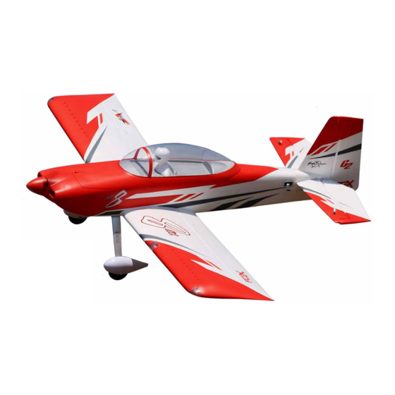
Unparalleled Flight Performance Control System with bounce-back control, three new optimized flight modes and preset Aura Flap System. Thank you for purchasing the Flex Innovations RV-8 60E G2, a massive, yet lightweight airframe that offers an incredibly wide flight envelope. From •... -
Page 4: Specifications
SPECIFICATIONS SPECIFICATIONS REPLACEMENT PARTS LISTING FPM4870A RV-8 60E G2: Super PNP Day Green FPM4880A RV-8 60E G2: Super PNP Night Green FPM4870B RV-8 60E G2: Super PNP Orange 1120 sq. in. FPM4880B RV-8 60E G2: Super PNP Night Orange (72.3 sq. dm.) FPM4870C RV-8 60E G2: Super PNP Day Red FPM4880C... -
Page 5: Special Language Definition
All instructions, warranties and other collateral documents are subject to change at the This product is not intended for sole discretion of Flex Innovations, LLC. For up-to-date product literature, please visit our website at www.flexinnovations.com and click on the RV-8 60E G2 and Aura 8 product use by children under 14 years pages. -
Page 6: Before You Begin
Our airplanes are designed around our Potenza LiPo batteries, and we recommend the Potenza 6S 5200mAh 40C LiPo in the RV-8 60E G2 based on our extensive testing and development. These batteries feature an EC5 connector, so no soldering is required for use in your RV-8 60E G2. All are available online at www.flexinnovations.com and your local Flex Innovations retailer. -
Page 7: Main Landing Gear Installation
MAIN LANDING GEAR INSTALLATION Required Tools and Fasteners: #1 Phillips Screwdriver (2) M3x12 Phillips Head Self-Tapping Screw 1.5mm Hex Driver (10) M3x8 Phillips Head Self-Tapping Screw 8mm Open End Wrench (4) M3x20 Phillips Head Machine Screw 12mm Open End Wrench Blue Thread Lock Adjustable Wrench (optional) (QTY 2) -
Page 8: Main Landing Gear Installation (Continued)
MAIN LANDING GEAR INSTALLATION (CONTINUED) 3. Locate the wheel and axle assembly. Use a 1.5mm hex driver to remove the set screws in the wheel collars. Apply blue thread lock to the set screws and re-assemble. 4. Slide the threaded end of the axle through the landing gear from the outside of the landing gear. Place a washer over the axle and apply blue thread lock to the axle threads. -
Page 9: Main Landing Gear Installation (Continued)
MAIN LANDING GEAR INSTALLATION (CONTINUED) 5. Use a #1 Phillips screwdriver and five M3x8 self-tapping screws to secure the outside half of the wheel pant to the landing gear assembly. 6. Apply blue thread lock to the four M3x20 machine screws. Use a #1 Phillips screwdriver and the four M3x20 screws to secure the landing gear to the fuselage. -
Page 10: Tail Wheel Installation
TAIL WHEEL INSTALLATION Required Tools and Fasteners: #1 Phillips Screwdriver (3) M3x7 Phillips Head Self-Tapping Screw (QTY 3) 1. Locate the vertical fin assembly, tail wheel and tail wheel retaining plate. Insert the tail wheel into the bottom of the rudder, being sure to orient it so that the tail wheel wire angles towards the tail as the wire moves away from the fuselage. -
Page 11: Vertical Fin Installation
VERTICAL FIN INSTALLATION Required Tools and Fasteners: 30-Minute Epoxy 220 Grit Sandpaper Craft Sticks (for mixing epoxy) Paper Towels Mixing Cup Isopropyl Alcohol 1. Locate the vertical fin assembly and vertical fin tube. The vertical fin tube is the shortest tube included with your aircraft. Test fit the vertical fin to the fuselage by inserting the tube into the vertical fin, and then into the fuselage. -
Page 12: Horizontal Stabilizer Installation
HORIZONTAL STABILIZER INSTALLATION Required Tools and Fasteners: #1 Phillips Screwdriver (4) M3x8 Phillips Head Self-Tapping Screw (QTY 4) 1. Insert and roughly center the carbon fiber horizontal stabilizer tube in the fuselage. 2. Insert both halves of the horizontal stabilizer onto the tube. Ensure that the control horn faces the bottom of the fuselage and that the elevator jointer tabs line up properly. -
Page 13: Main Wing Installation
MAIN WING INSTALLATION Required Tools and Fasteners: (2) M4x18 Thumb Machine Screw WARNING REMOVE THE AILERON AND FLAP SERVO SCREWS AND APPLY BLUE THREAD LOCK TO THE SCREWS. RE-INSTALL THE SCREWS AND TIGHTEN FULLY. FAILURE TO DO SO MAY RESULT IN A CRASH 1. -
Page 14: Motor, Cowling And Propeller Installation
MOTOR, COWLING AND PROPELLER INSTALLATION Required Tools and Fasteners: Motor Assembly (4) M4x8 Phillips Flat Head Screw Prop Adapter Assembly 2.5mm Hex Driver (4) M3x10 Socket Head Cap Screw #2 Phillips Screwdriver (4) M3x22 Phillips Button Head Screw Blue Thread Lock (QTY 4) (QTY 4) (QTY 4) Note: Do not complete transmitter, receiver and/or Aura setup with the propeller installed. -
Page 15: Exhaust Installation
EXHAUST INSTALLATION Required Tools and Fasteners: Medium CA CA Accelerator 1. Locate the two black foam scale exhaust pieces. Use medium CA to secure the exhaust as shown in the photo below. You can also use CA accelerator to help speed up the process. NIGHT RV-8 60E G2 LED CONNECTIONS If you have purchased the Night version of the RV-8 60E G2, this page will cover all LED light connections. -
Page 16: Aura 8 Afcs
flying experience, but it never interferes with the pilot’s control. The Aura 8 AFCS comes configured with Flight Modes (dual rates, expos and gyro settings) set by the Flex Innovations team, and offers a great starting point for most pilots. Since these are already configured for you in the Aura, there is no need to set up dual rates, expos or flaps in your transmitter. -
Page 17: Transmitter Setup
TRANSMITTER SETUP The included Aura 8 is designed to work seamlessly with all popular transmitter and receiver brands, however, transmitter setup is significantly different than when setting up a model without Aura. Follow these steps: Start with a new model memory in your transmitter. Reset it to be certain it is set to defaults. Adjust your transmitter settings according to the Transmitter Configuration Guide below. -
Page 18: Connecting Your Receiver To Aura
CONNECTING YOUR RECEIVER TO AURA Serial Receivers Spektrum Remote Receivers If using a standard serial receiver, connect the provided male to male cable to If using two Spektrum Remote Receivers, connect them to your receiver’s serial port. Connect the other end of the cable to Aura Port B Aura Mini Port A and Mini Port B using the cable provided noting proper polarity. -
Page 19: Rudder And Elevator Linkage Installation
RUDDER AND ELEVATOR LINKAGE INSTALLATION Required Tools and Fasteners: Elevator and Rudder Pushrod Assemblies #2 Phillips Screwdriver (4) M2x10 Phillips Head Machine Screw #0 Phillips Screwdriver (4) M2 Flat Washer Needle-Nosed Pliers (or Hemostats) (4) M2 Lock Nut Blue Thread Lock (4) M3x6 Phillips Head Machine Screw (QTY 4) (QTY 4) (QTY 4) -
Page 20: Rudder And Elevator Linkage Installation (Continued)
RUDDER AND ELEVATOR LINKAGE INSTALLATION (CONTINUED) WARNING Note: Do not use thread locker on the bolts holding the push rods to the servo arms or the control horns! Using thread locker will weaken the plastic, void your warranty, and cause your airplane to crash! 4. -
Page 21: Connecting Battery/Arming Esc
CONNECTING BATTERY/ARMING ESC Observe the following procedures to safely power up your model after it has been bound. Ensure propeller is removed unless this sequence is followed to power up before flight. 1. Turn on the transmitter. Lower the throttle stick AND throttle trim to their lowest settings. -
Page 22: Control Direction Test
CONTROL DIRECTION TEST Refer to the chart below to determine the proper control surface responses to transmitter control inputs. If controls are reversed, DO NOT REVERSE CONTROLS IN YOUR TRANSMITTER OR IN THE AURA CONFIG TOOL. Email us at support@flexinnovations.com for corrective action. Note that BOTH the Transmitter Control Direction Test AND the Flight Controller Sensor Direction Test MUST BE PASSED! IF EITHER ONE DOES NOT PASS, DO NOT FLY! NOTE: There is pre-configured rudder to aileron and rudder to elevator mixing programmed into the Aura. -
Page 23: Aura Sensor Direction Test
AURA SENSOR DIRECTION TEST Perform a test of the gyro system to verify the corrections made for a given movement are correct. If any of the tests do not result in the correct reaction from the airplane's gyro system, DO NOT FLY THE AIRPLANE, and contact us via email at support@flexinnovations.com The flight control system activates with RF broadcast. -
Page 24: Cowling, Propeller And Spinner Installation
COWLING, PROPELLER AND SPINNER INSTALLATION Required Tools and Fasteners: (2) M3x8 Phillips Button Head Screw M8 Nut & Washer for Propeller Adapter (1) M3x10 Phillips Button Head Screw #1 Phillips Screwdriver (QTY 2) (QTY 1) 1. Use a #1 Phillips screwdriver and two M3x8 Phillips button head screws to secure the the cowling to the aircraft. 2. -
Page 25: Battery Installation
BATTERY INSTALLATION Push the spring-loaded battery latch tab back to release the battery hatch. Lift the hatch away from the fuselage, starting at the front. Remove the battery tray by loosening the thumb screw. Slide the tray rearward as you gently lift the tray away from the fuselage. Install an adhesive-backed hook strip to the battery tray, and an adhesive-backed loop strip to the battery. -
Page 26: Pre-Flight Checklist
PRE-FLIGHT CHECKLIST To help ensure a successful first flight, as well as many flights after, perform a few simple pre-flight checks to be sure the aircraft is ready to fly: Verify the elevators and rudder are properly hinged and in good working order. Pinch a control surface between your thumb and forefinger and grasp the stabilizers with your other hand. -
Page 27: G2 Aura Optional Features Configuration
RV-8 60E G2 AURA OPTIONAL FEATURES CONFIGURATION The Aura installed in your RV-8 60E G2 comes with the Quick Set feature. Quick Set allows the pilot to adjust options in the Aura without the use of a computer. The options of the RV8 60E G2 are described below: •... -
Page 28: Flying Your Rv-8 60E G2
FLYING YOUR RV-8 60E G2 Selecting a Flying Site Trimming Selecting a flying site is critical to a successful flight. Airplanes require a lot The first several flights on your new RV-8 60E G2 should be more room than other R/C products, therefore, a neighborhood or dedicated to trimming and setup. -
Page 29: Airframe Repairs
AIRFRAME REPAIRS The RV-8 60E G2 is molded from durable EPO foam and is repairable with most adhesives. Similar to building and repairing wood or composite airplanes, the correct glue for a given application is critical to the repair holding and not breaking again. For major repairs, such as a broken fuselage, epoxy is preferred because it allows time to correct any misalignment. -
Page 30: Aircraft Troubleshooting Guide
AIRCRAFT TROUBLESHOOTING GUIDE Should you encounter any abnormal situations with your RV-8 60E G2, refer to the table below to determine the probable cause and a recommended solution for the issue. If the required solution does not rectify the problem, please contact product support at support@flexinnovations.com for further assistance. NOTICE Unless specifically required, ALWAYS troubleshoot the airplane with the propeller removed. -
Page 31: Limited Warranty
LIMITED WARRANTY Questions & Assistance Warranty Coverage Contact Us By: Flex Innovations LLC and its authorized resellers (“Flex”) warrant to the E-Mail – support@flexinnovations.com original purchaser that this product (the “Product”) will be free from Phone – 1 (866) 310-3539 defects in materials and workmanship at the date of purchase. - Page 32 Enjoy your Flex Innovations RV-8 60E G2! w w w. f l e x i n n o v a t i o n s . c o m © 2023 Flex Innovations, LLC. All rights reserved. Potenza™ is a trademarks of Flex Innovations LLC DSM®, DSM2™, and DSMX™...
Need help?
Do you have a question about the RV-8 60E G2 SUPER PNP and is the answer not in the manual?
Questions and answers