Table of Contents
Advertisement
Advertisement
Table of Contents

Related Manuals for Flex innovations FV-31 Cypher


Summary of Contents for Flex innovations FV-31 Cypher
- Page 3 BEFORE CONTINUING WITH THIS INSTRUCTION MANUAL OR ASSEMBLY OF YOUR AIRCRAFT, PLEASE VISIT OUR WIKI SUPPORT SITE FOR THE LATEST PRODUCT UPDATES, FEATURE CHANGES, MANUAL ADDENDUMS AND FIRMWARE CHANGES FOR BOTH YOUR AIRCRAFT AND THE INSTALLED FLEXF3 STABILIZATION SYSTEM. wiki.flexinnovations.com/wiki/Cypher...
-
Page 4: Table Of Contents
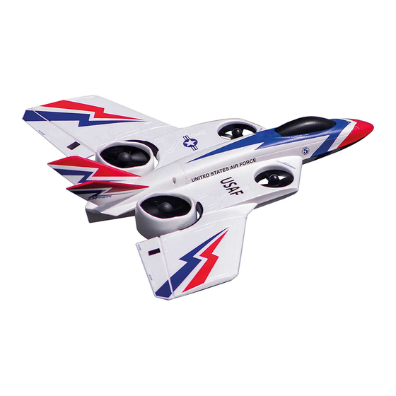
Ventral Fin Installation ............INTRODUCTION Unparalleled Flight Performance The Flex Innovations Plug-and-Play FV-31 Cypher VTOL EDF is the Factory-installed and custom-tuned FLEXF3 Flight most advanced and versatile vertical take off and landing (VTOL) and Control System short take off and landing (STOL) model aircraft of its type. Two fixed... -
Page 5: Specifications
FPZDS15 DS-15 Sub-Micro Servo (370mm lead) FPZMCYPR Cypher Rear Motor - Right The assembly of the FV-31 Cypher can be accomplished in FPZMCYPL Cypher Rear Motor - Left less than one hour. Prior to assembling the aircraft, it is FPZMCYPFR... -
Page 6: Special Language Definitions
3. This model must be assembled according to these instructions. Do not alter or modify the model outside of these instructions provided by Flex Innovations LLC as doing so may render it unsafe and/or unflyable. It is your responsibility to ensure the airworthiness of the model. -
Page 7: Flexf3 Control System
Description of Pre-Configured Control Modes and Flight Configurations The FV-31 Cypher comes pre-configured with two Control Profiles (Beginner or Advanced) that are controlled by your transmitter's channel 5 and three Flight Configurations (Hover Configuration, 45° "Magic" Configuration and Conventional Configuration) that are controlled by transmitter channel 6. -
Page 8: Transmitter Setup
DEATH OR SERIOUS INJURY. TRANSMITTER SETUP The FLEXF3 system is designed to work with all major transmitter and receiver brands. The FV-31 Cypher requires a minimum 6-channel programmable transmitter for proper function. When programming your transmitter, start with a freshly reset new model memory in your transmitter. -
Page 9: Spektrum Transmitter & Receiver Setup
SPEKTRUM TRANSMITTER AND RECEIVER SETUP Transmiter Setup Follow the chart below for setup of your Spektrum transmitter. Be sure to start with a blank and freshly reset model memory before starting setup. TRANSMITTER CONFIGURATION GUIDE Spektrum Frame Rate 11ms Preferred (22ms OK) Wing/Tail Type 1 Aileron, 1 Elevator, 1 Rudder End Points 148%... - Page 10 SPEKTRUM TRANSMITTER AND RECEIVER SETUP (CONTINUED) Receiver Selection For Spektrum users, you must use an SRXL capable receiver. We've listed a few options below for FLEXF3 compatible receivers: Spektrum Quad Race Serial Receiver with Telemetry (SPM4649T) - Highest Recommended Spektrum AR8010T (SPMAR8010T) Spektrum AR9030T (SPMAR9030T) Spektrum AR7700 (SPMAR7700) - no telemetry Spektrum remote receivers are not supported with this product.
- Page 11 SPEKTRUM TRANSMITTER AND RECEIVER SETUP (CONTINUED) Connection A (without Betaflight Telemetry) (Continued) Spektrum AR8010T with SRXL 3 to 4 Pin Male to Male (Provided) S + - To SRXL Port Connection B (with Betaflight Telemetry) Spektrum AR4649T Male End Female End (Bind) Betaflight (PC) or SpeedyBee (mobile) application setup required for Connection B.
- Page 12 SPEKTRUM TRANSMITTER AND RECEIVER SETUP (CONTINUED) Connection B (with Betaflight Telemetry) (Continued) Spektrum AR8010T with SRXL 3 to 4 Pin Male to Male (Provided) S + - To SRXL Port Betaflight (PC) or SpeedyBee (mobile) application setup required for Connection B.
- Page 13 SPEKTRUM TRANSMITTER AND RECEIVER SETUP (CONTINUED) Connection B (with Betaflight Telemetry) Application Setup If you have chosen to utilize a Betaflight Telemetry connection (Connection B), please follow the steps below to activate Telemetry on the Betaflight PC application or SpeedyBee mobile application. If you have chosen Connection A (without Betaflight Telemetry, please proceed to the section on page 14 titled "Binding".
- Page 14 Connection B (with Betaflight Telemetry) Application Setup (Continued) If you have chosen Connection A (without Betaflight Telemetry, please proceed to the section on Page 13 titled "Binding". Click the Configuration tab on the left side of the application. Scroll down until you see the switch tab for Telemetry. Slide this tab into the on (yellow) position. Click Save and Reboot in the lower right hand corner to save the settings to the F3 controller.
-
Page 15: Spektrum Transmitter & Receiver Setup
SPEKTRUM TRANSMITTER AND RECEIVER SETUP (CONTINUED) Binding Reference your transmitter and receiver's instruction manual for specifics on the bind process. With the aircraft and transmitter powered off, insert a bind plug into your receiver's bind port (or press and hold the bind button on your receiver if available). -
Page 16: Futaba Transmitter & Receiver Setup
FUTABA TRANSMITTER AND RECEIVER SETUP Transmiter Setup Follow the chart below for setup of your Futaba transmitter. Be sure to start with a blank and freshly reset model memory before starting setup. TRANSMITTER CONFIGURATION GUIDE Futaba Wing/Tail Type 1 Aileron, 1 Elevator, 1 Rudder End Points 120% Thro/Ail/Ele/Rud... - Page 17 FUTABA TRANSMITTER AND RECEIVER SETUP (CONTINUED) Receiver Selection For Futaba users, you must use an S.Bus capable receiver. We've listed a few options below for FLEXF3 compatible receivers: Futaba R2001SB S.Bus S-FHSS Receiver (FUTR2001SB) - Highest Recommended Futaba R6303SB S.Bus FASST Receiver (FUTR6303SB) Futaba R7003SB S.Bus FASSTest Receiver (FUTR7003SB) Receiver Installation Install your Futaba receiver and antennas according to your receiver's instruction manual.
- Page 18 FUTABA TRANSMITTER AND RECEIVER SETUP (CONTINUED) Application Setup If you you are using a Futaba S.BUS connection, please follow the steps below to complete setup on the Betaflight PC application or SpeedyBee mobile application. Download the Betaflight Configurator for your computer or the SpeedyBee Application for your mobile device. You can search for these applications online (or in your mobile device's app store) or visit the web addresses shown below.
- Page 19 FUTABA TRANSMITTER AND RECEIVER SETUP (CONTINUED) Click the Configuration tab on the left side of the application. Scroll down until you see the section titled "Receiver". Verify that the first drop-down menu (Receiver Mode) has "Serial- based receiver (SPEKSAT, SBUS, SUMD) selected. Once verified, click the second drop down menu (Serial Receiver Provider), and choose SBUS.
- Page 20 FUTABA TRANSMITTER AND RECEIVER SETUP (CONTINUED) Re-connect to the FLEXF3. Navigate to the Receiver tab on the left hand side of the page. On the right-hand side you will see Channel Map (Channel Order). By default, it is set to TAER1234. Click the drop down menu and select the proper channel order for Futaba: AETR1234.
-
Page 21: Futaba Transmitter & Receiver Setup
FUTABA TRANSMITTER AND RECEIVER SETUP (CONTINUED) Binding Some Futaba S.Bus receivers will need to be configured and set up to output the proper S.Bus signal and order. Consult your receiver manual for information on this process. If you have questions on binding your particular receiver and transmitter, consult your transmitter and receiver's instruction manual. -
Page 22: Connecting A Battery/Arming The Esc
CONNECTING A BATTERY/ARMING THE ESC WARNING Observe the following procedures to safely power up your model after it has been bound. Ensure propellers are removed unless this sequence is followed to power up before flight. When making adjustments to linkages, transmitter Lower the throttle stick it's lowest setting and turn on the settings or the flight control system, remove the transmitter. -
Page 23: Rear Fan Angle Adjustment
REAR FAN ANGLE ADJUSTMENT The following steps will guide you through the adjustment and setup of the rear fans. You must have your receiver bound and control surfaces working before completing these steps. You will also need to have the aircraft on a stand where the rear fans can tilt and move freely. -
Page 24: Rear Fan Angle Adjustment
REAR FAN ANGLE ADJUSTMENT (CONTINUED) Move your Flight Configuration switch (channel 6) to the 90 degree "Conventional Configuration" position. Align the provided 90 degree gauge with the panel line on the top surface of the wing and the center of a rear fan. Adjust your transmitter's channel 6 end point (travel adjust or ATV) to set the angle of the rear fans so that they match the provided gauge. -
Page 25: Landing Gear Installation
LANDING GEAR INSTALLATION Required Tools and Fasteners: #1 Phillips Screwdriver (4) M3x8 Phillips Head Self-Tapping Screw (QTY 4) Locate the main landing gear, four M3x8 self-tapping screws and two plastic main gear retaining plates. Insert the main landing gear into the fuselage slots. Place the retaining plates over the landing gear wire in the slot in the fuselage, noting that their orientation matches the landing gear wire shape. - Page 26 LANDING GEAR INSTALLATION (CONTINUED) Required Tools and Fasteners: 1.5mm Hex Driver Locate the nose gear strut assembly. Insert the strut into the mount in the bottom of the fuselage and through the nose gear steering arm. Be sure to orient the coil on the strut towards the rear of the aircraft. Insert the strut until it is flush with the top of the mount inside the fuselage (under the battery hatch).
-
Page 27: Ventral Fin Installation
VENTRAL FIN INSTALLATION Required Tools and Fasteners: Medium CA Locate the ventral fin. Test fit the fin in place, noting that the more angled edge fits towards the nose of the aircraft. Use medium CA to secure the ventral fin in place. -
Page 28: Vertical Fin Installation
Locate the two vertical fins as well as the rear hatch removed when setting the rear fan tilt. Test fit the vertical fins into the rear hatch, noting that they only fit in one direction and on a particular side (the FV-31 Cypher logos should face out). If your Cypher has painted mating surfaces, scuff them with a medium grit sandpaper to remove paint and promote adhesion. -
Page 29: Main Wing Installation
MAIN WING INSTALLATION Required Tools and Fasteners: M2x8 Self-Tapping Screws Clear Tape #1 Phillips Screwdriver Remove the canopy hatch and locate the two wing tubes. Test fit each of the wing tubes into the wings and then into the fuselage. Slide the wing tubes into the fuselage, being sure they engage fully with the battery tray. - Page 30 MAIN WING INSTALLATION (CONTINUED) Slide the wing into the fuselage while guiding the servo wire into the slot in the bottom of the wing. Note that there is a slightly larger recess in the wing that will fit the servo lead connection point. Apply clear tape at the trailing and leading edge of the wing, both top and bottom, to secure it in place.
-
Page 31: Elevon Setup
ELEVON SETUP Required Tools and Fasteners: Elevon Centering Gauge Flat Blade Screwdriver Power on your transmitter and the Cypher being sure you have control. Place your FLEXF3 Profile switch (Channel 5) into the Advanced Profile position. You can confirm that it is in the correct position by rotating the aircraft to a specific angle away from level. If the aircraft only attemps to correct while it is in motion, you are in the correct profile. -
Page 32: Beginner Profile Calibration
BEGINNER PROFILE CALIBRATION In order to ensure the Beginner Profile works properly, you must calibrate the FLEXF3 sensor. If you do not plan to fly in the Beginner Profile, it is still highly recommended that you calibrate the sensor. If you have a crash or replace parts, it is always a good idea to repeat this process to ensure proper flight performance. Connect the FLEXF3 to the Betaflight PC or SpeedyBee mobile applications with the provided USB cable or bluetooth module. - Page 33 BEGINNER PROFILE CALIBRATION (CONTINUED) In the Betaflight or Speedy Bee application, navigate to the Setup tab on the left hand side of the screen. Once the aircraft is in a stable, proper position (reference step 2) as well as motionless, click Calibrate Accelerometer in the application. Wait until the calibration has been completed, then click disconnect and remove the USB or blueooth module from the FLEXF3.
-
Page 34: Transmitter Control Direction Test
TRANSMITTER CONTROL DIRECTION TEST Refer to the chart below to determine the proper control surface directions. If controls are reversed, DO NOT REVERSE CONTROLS IN THE TRANSMITTER OR THE APPLICATIONS. Email us at support@flexinnovations.com for corrective action. Note that BOTH the Transmitter Control Direction Test AND the Flight Controller Sensor Direction Test MUST BOTH BE PASSED! IF ONE DOES NOT PASS, DO NOT FLY! Note: The rudder stick movement controls both the motors and nose gear steering for yaw control. -
Page 35: Flight Control Sensing Direction Test
FLIGHT CONTROL SENSING DIRECTION TEST Perform a test of the gyro system to verify the corrections made for a given movement are correct. If any of the tests do not result in the correct reaction for the airplane's gyro system, DO NOT FLY THE AIRCRAFT, and contact us via email at support@flexinnovations.com. The flight control system activates with RF broadcast. -
Page 36: Fan Installation
The fans on the FV-31 Cypher spin in different directions for stability and performance. Power the model and verify the motors spin in the proper direction as shown in the diagram below. Once confirmed, remove power from the model. - Page 37 FAN INSTALLATION (CONTINUED) Turn the fans onto the motor shafts. Use a #1 Phillips screwdriver and the screws removed in step one to reattach the motors to the airframe. The rear motors use a traditional fan nut and spinner but do have different thread directions as with the front motors. Place the propeller over the appropriate motor, paying close attention to the direction (reference the diagram on the previous page).
-
Page 38: Fan Installation
FAN INSTALLATION (CONTINUED) Place the spinner over the fan while noting the orientation of the fan blades and spinner cutouts. Use a Phillips screwdriver and a M3x5 machine screw to secure the spinner to the fan adapter. Repeat for the other side. -
Page 39: Center Of Gravity Verification
Ribbe. Lift the airplane from the underside of the wing to check CG. Setting the center of gravity is one of the most important steps for success, particularly with a new aircraft. The FV-31 Cypher is a unique flying aircraft that couples multirotor and airplane flight characteristics together. -
Page 40: Flying Tips - Controls And Flight Profiles
Controls The FV-31 Cypher is a totally unique aircraft and has several different types of controls depending on your selected Flight Configuration and Flight Profile. Check out the information below and on the following pages for details on controls and flying tips for each Flight Configuration and Profile. -
Page 41: Flying Tips - Flight Configurations And First Flights
3 feet (1m). Landing There are various ways to land the FV-31 Cypher. For your first flight, you may choose not to make any transitions. If that is the case, you will be landing in the same Flight Configuration that you took off in. -
Page 42: Flying Tips - First Flights, Transitions And Trimming
Conventional), transitions occur when changing from one flying dedicated to trimming and setup. Switch to the Advanced Profile state to another. Flex Innovations defines two flying states when while in Conventional Configuration and fly the aircraft at talking about transitions; flying on the wing or flying on fan approxiately 65% power. -
Page 43: Troubleshooting Guide
AIRCRAFT TROUBLESHOOTING GUIDE Should you encounter any abnormal situations with your aircraft, refer to the matrix below to determine a probable cause and a recommended solution for the action. If the required solution does not rectify the problem, please contact product support for further assistance. NOTICE Unless specifically required, ALWAYS trouble shoot with fan blades removed, motors unplugged from the ESC or with the aircraft securely restrained and clear of people and loose objects. - Page 44 AIRCRAFT TROUBLESHOOTING GUIDE Should you encounter any abnormal situations with your aircraft, refer to the matrix below to determine a probable cause and a recommended solution for the action. If the required solution does not rectify the problem, please contact product support for further assistance. NOTICE Unless specifically required, ALWAYS trouble shoot with fan blades removed, motors unplugged from the ESC or with the aircraft securely restrained and clear of people and loose objects.
-
Page 45: Flexf3 Wiring Diagram
MICRO USB (uses UART1) BLUE LED (POWER) UART2 BLUETOOTH 4.3V (19200 BAUD) RED LED UART 3 (STATUS) (RX INPUT) GND 4.3V BOOT VBATT BUZZER/LED 4.3V FLIGHT PACK VOLTAGE INPUT MTR 3 (ORANGE) FAN TILT MTR 4 (YELLOW) MTR 2 (VIOLET) MTR 1 (GREEN) NOSEWHEEL 5V (BEC INPUT) -
Page 46: Ama Safety Code
Academy of Model Aeronautics National Model Aircraft Safety Code Effective January 1, 2015 GENERAL: A model aircraft is a non-human-carrying aircraft RC model aircraft must use the radio-control frequencies currently capable of sustained fight in the atmosphere. It may not exceed allowed by the Federal Communications Commission (FCC). -
Page 47: Limited Warranty
LIMITED WARRANTY Warranty Coverage Questions & Assistance Flex Innovations, LLC and its authorized resellers ("Flex") warrant Visit www.flexinnovations.com/articles.asp?ID=269 to find to the original purchaser that the product purchased (the "Product") customer support in your region. it will be free from defects in materials and workmanship at the date of purchase. - Page 50 . f l e x i n n o v a t i o n s . c o m ©2019 Flex Innovations LLC Premier Aircraft™, Potenza™, and Top Value RC™ are trademarks or registered trademarks of Flex Innovations LLC DSM®, DSM2™, and DSMX™ are trademarks or registered trademarks of Horizon Hobby LLC Futaba™...
Need help?
Do you have a question about the FV-31 Cypher and is the answer not in the manual?
Questions and answers
What flight controller can I use in my fv31