Table of Contents
Advertisement
Advertisement
Table of Contents

Related Manuals for Flex innovations MAMBA 10


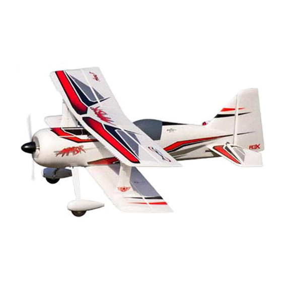
Summary of Contents for Flex innovations MAMBA 10
- Page 1 DESIGNED BY...
- Page 2 BEFORE CONTINUING WITH THIS INSTRUCTION MANUAL OR ASSEMBLY OF YOUR MAMBA 10, PLEASE VISIT OUR WIKI SUPPORT SITE FOR THE LATEST PRODUCT UPDATES , FEATURE CHANGES, MANUAL ADDENDUMS AND FIRMWARE CHANGES FOR BOTH YOUR MAMBA 10 AND THE INSTALLED AURA 8 ADVANCED FLIGHT CONTROL SYSTEM.
-
Page 3: Table Of Contents
Only years of experience designing aircraft in this category can produce Innovative plywood sub-frame connects the motor § the Mamba 10's aggressive, yet forgiving characteristics. Designer Quique securely to the fuselage while providing superior Somenzini knows how to optimize biplane aerodynamics like no other, battery mounting and cooling having won F3A and 3D world championships with his biplane designs. -
Page 4: Speci Cations
Aura 8 for Mamba 10 FPZAURA08ZZM10 The assembly of the Mamba 10 can be accomplished in less than one hour. Prior to assembling the airplane, it is advisable to charge your battery so that you are ready to begin setup upon completion of the assembly of your model. -
Page 5: Special Language De Nitions
3. This model must be assembled according to these instructions. Do not alter or modify the model outside of these instructions provided by Flex Innovations, Inc, as doing so may render it unsafe and/or un yable. It is your responsibility to ensure the airworthiness of the model. -
Page 6: Main Landing Gear Installation
MAIN LANDING GEAR INSTALLATION Required Tools and Fasteners: #1 Phillips Screwdriver, (4) M3x12 self-tapping Phillips head cap screws 1. Insert the landing gear assembly into the slot in the bottom of the fuselage. The gear will sweep forward. 2. Install the cover plate over the landing gear slot and attach with (4) M3x12 self-tapping Phillips head cap screws . TAILWHEEL INSTALLATION Required Tools and Fasteners: #1 Phillips Screwdriver, (3) M3x12 self-tapping Phillips head cap screws 1. -
Page 7: Horizontal Stabilizer Installation
HORIZONTAL STABILIZER INSTALLATION Required Tools and Fasteners: Clear Tape (4 strips) 1. Insert the horizontal stabilizer tube into the fuselage and roughly center. 2. Slide the left and right stabilizer halves onto the tube. Ensure that the control horn orients towards the belly of the airplane and that the elevator joiner tabs are properly indexed. -
Page 8: Transmitter Setup
It is reccomended that for pilots with less experience, set up a transmitter dual rate of 75% for the The Aura Con g Tool can be used on any Windows-based PC or aileron channel only if using end points of 125%. The ailerons of the Mamba 10 are very responsive tablet. Download at www. exinnovations.com/AuraCon gTool. -
Page 9: Receiver Installation/Servo Connections
RECEIVER INSTALLATION/SERVO CONNECTIONS Aura will auto-detect modern digital receiver connection. Using a modern digital receiver connection gives the Aura access to precise data of each channel for additional gyro enabled outputs, simpli es DEFAULT AURA CONNECTIONS wiring, and allows for more advanced features. To connect a modern digital receiver connection, follow the steps on this page, then skip S1 Throttle (ESC/BEC) ahead to the control direction test on page 12. -
Page 10: Connecting Battery/Arming Esc
In order to utilize this type of receiver connection with your Mamba 10, male to male servo leads to connect the corresponding receiver ports to Aura are required. A minimum 6-channel receiver is required to setup Aura with PWM connections. -
Page 11: Main Wing Installation
MAIN WING INSTALLATION Required Tools and Fasteners: #1 Phillips Screwdriver, (4) M2x6mm self-tapping Phillips head screws, (1) M3x70mm Phillips machine screws, (8) M3x12mm self-tapping Phillips head screws 1. Locate the (4) cabane struts, fuselage, and top wing. Dry t the cabane struts into the moulded mounts in the wing and fuselage to ensure proper tment and alignment. - Page 12 MAIN WING INSTALLATION (CONTINUED) 7. Attach the interplane struts to the bottom wing using (4) M3x12mm Phillips head cap screws. While the struts are directional and will only t one way, ensure that the logo is oriented outwards and on the bottom side of the strut, oriented upright. 8.
-
Page 13: Control Direction Test
CONTROL DIRECTION TEST Refer to the chart below to determine the proper control surface directions. If controls are reversed, DO NOT REVERSE CONTROLS IN TRANSMITTER OR IN THE AURA CONFIG TOOL. Email us at support@ exinnovations.com for corrective action. Note that BOTH the Transmitter Control Direction Test AND the Flight Controller Sensor Direction Test MUST BOTH BE PASSED! IF ONE DOES NOT PASS, DO NOT FLY! NOTE: There is pre-con gured rudder to aileron and rudder to elevator mixing programmed into the Aura. -
Page 14: Flight Control Direction Sensing Test
FLIGHT CONTROL SENSING DIRECTION TEST Perform a test of the gyro system to verify the corrections made for a given movement are correct. If any of the tests do not result in the correct reaction from the airplane's gyro system, DO NOT FLY THE AIRPLANE, and contact us via email at support@ exinnovations.com The ight control system activates with RF broadcast. -
Page 15: Linkage Setup
NOTICE The DS15 servos installed in your Mamba 10 are high quality, digital servos with all metal gear train and ultra- ne gear mesh. This ne resolution and high tooth count output shaft means that the servo arms pre-installed on the servos may inadvertantly be misaligned, yet appear properly installed. -
Page 16: Battery Installation
BATTERY INSTALLATION 1. Push the spring-loaded battery latch tab back to release the battery hatch. 2. Press the battery to the battery tray and secure with the provided hook-and-loop strap. With the recommended battery, the front edge align with the front edge of the battery hatch. 3. -
Page 17: Flying Your Mamba 10
Trimming Selecting a ying site is critical to a successful ight. Airplanes The rst several ights on your new Mamba 10 should be require a lot more room than other R/C products, therefore, a dedicated to trimming and setup. Fly the airplane at 2/3 power neighborhood or parking lot is less than ideal. -
Page 18: Advanced Mamba 10 Setup
Crow The Mamba 10 is the only PNP 3D foam biplane on the market in this size with four individual aileron servos instead of two servos with interconnect linkages. This exibilty, usually only found in larger biplanes, allows the Mamba 10 to take advantage of several key aileron setups, primarily the “world famous QQ biplane crow”. -
Page 19: Airframe Repairs
AIRFRAME REPAIRS The Mamba 10 is molded from durable EPO foam and is repairable with most adhesives. Similar to building and repairing wood or compos- ite airplanes, the correct glue for a given application is critical to the repair holding and not breaking again. For major repairs, such as a broken fuselage, epoxy is preferred because it allows time to correct any misalignment. -
Page 20: Servicing The Power System
OPTIONAL WHEEL PANT REMOVAL For yers that want the lightest possible setup, or that y o of rough/unimproved elds, the wheelpants on the Mamba 10 are designed to be removable. Two wheel collars have been provided in the hardware bag to retain the wheels after the wheelpants are removed. -
Page 21: Aircraft Troubleshooting Guide
AIRCRAFT TROUBLESHOOTING GUIDE Should you encounter any abnormal situations with your Mamba 10, refer to the matrix below to determine the probable cause and a recommended solution for the action. If the required solution does not rectify the problem, please contact product support for further assistance. -
Page 22: Limited Warranty
LIMITED WARRANTY Warranty Coverage Questions & Assistance Flex Innovations, Inc. and its authorized resellers (“Flex”) warrant to Visit http://www. exinnovations.com/ ex-authorized-reseller the original purchaser that the product purchased (the “Product”) it for customer support in your region. will be free from defects in materials and workmanship at the date of purchase. -
Page 23: Ama Safety Code
Academy of Model Aeronautics National Model Aircraft Safety Code E ective January 1, 2014 GENERAL: A model aircraft is a non-human-carrying aircraft capable 4. RC model aircraft must use the radio-control frequencies currently of sustained ight in the atmosphere. It may not exceed limitations of this allowed by the Federal Communications Commission (FCC). - Page 24 O cially Licensed Product © 2017 Flex Innovations, Inc. Premier Aircraft™, Potenza™, and Top Value RC™ are trademarks or registered trademarks of Flex Innovations, Inc. DSM®, DSM2™, and DSMX™ are trademarks of Horizon Hobby, Inc. Futaba is a registered trademark of Futaba Denshi Kogyo Kabushiki Kaisha Corporation of Japan.
Need help?
Do you have a question about the MAMBA 10 and is the answer not in the manual?
Questions and answers