Table of Contents
Advertisement
Quick Links
Advertisement
Table of Contents

Related Manuals for Flex innovations Cap 232EX 70cc


Summary of Contents for Flex innovations Cap 232EX 70cc
- Page 1 Instruction Manual ARF and ARFSV...
- Page 2 BEFORE CONTINUING WITH THIS INSTRUCTION MANUAL OR THE ASSEMBLY OF YOUR AIRCRAFT, PLEASE VISIT OUR WIKI SUPPORT SITE FOR THE LATEST PRODUCT UPDATES, FEATURE CHANGES AND MANUAL ADDENDUMS FOR THIS PRODUCT. wiki.flexinnovations.com/wiki/Cap_232EX_70cc...
-
Page 3: Table Of Contents
TABLE OF CONTENTS Introduction ..........................1 Specifications: ................................. 2 Required Equipment: ..............................2 Optional Equipment: ..............................3 Ultracote®/Oracover® Colors: ............................. 3 Using this Manual ..........................4 ARF .............................. 6 Aileron and Elevator Control Horn Installation ................. 6 Control Horn Installation ............................6 Aileron Servo and Linkage Installation .................. - Page 4 Decal Installation ........................... 59 Final Setup and Flying Notes ....................61 Center of Gravity ..........................61 Aura 8 Professional ........................62 Range Testing ..........................63 Before First Flight .......................... 63 AMA Safety Code ........................... 64 Replacement Parts ......................... 65 Optional Accessories ........................66 Limited Warranty ........................
-
Page 5: Introduction
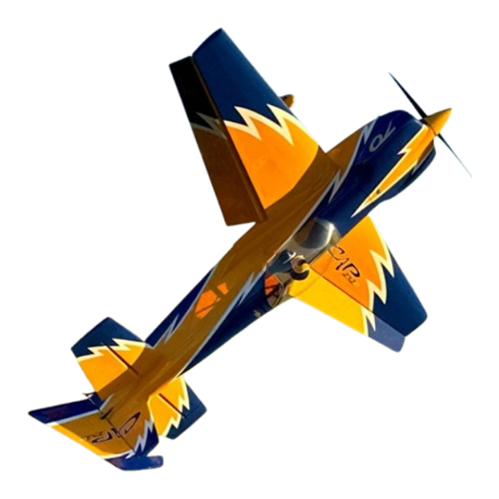
INSTALLED Flex DS49010BLHV servos, G-10 control horns, metal clamping servo arms and premade linkages to get you in the air even faster! The Cap 232EX 70cc is available in two distinctive color schemes by Clint Sweet Designs, perfectly marrying the aircraft’s looks with its high-performance capabilities. -
Page 6: Specifications
(2) 36-inch (920 mm) FPZ1048 Rudder: Tail-Mounted Push-Pull – (1) 36-inch (920 mm) FPZA1048 Forward-Mounted Pull-Pull – None Required Throttle: (1) 9-inch (230cm) FPZA1044 Spinner: Spinner: 4-inch (101 mm) Flex Innovations 4-inch Carbon Fiber Spinner, Edge Style (FPMA1031 & FPMA1032) recommended... -
Page 7: Optional Equipment
Holy Smokes G2 Smoke System FPM2314 Flex Innovations Premium Wing and Tail Bag Set FPM2327A Cap 232EX 70cc Pilot and Cockpit Set, Red FPM227B Cap 232EX 70cc Pilot and Cockpit Set, Yellow FPM2329A Cap 232EX 70cc Premium Decal Set Red Scheme... -
Page 8: Using This Manual
All instructions, warranties and other collateral documents are subject to change at the sole discretion of Flex Innovations, LLC. For up-to-date product literature, please visit our website at www.flexinnovations.com and navigate to the product page for this product. - Page 9 Cap 232EX 70cc Instruction Manual 7. If you are not an experienced pilot, or have not flown a high-performance model before, it is recommended that you seek assistance from an experienced pilot in your R/C club for your first flights. If you're not a member of a club, the Academy of Model Aeronautics (AMA) has information about clubs in your area whose membership includes experienced pilots.
-
Page 10: Arf
Cap 232EX 70cc Instruction Manual If your airplane is the ARF version start building from this page through the end of this manual. If you have the ARFSV version, please proceed from Page 14 through the end of this manual. - Page 11 Cap 232EX 70cc Instruction Manual ⃞ 2. Scuff each control horn with medium grit sandpaper where it enters the control surface. Use a paper towel and isopropyl alcohol to clean up the control horn after it has been scuffed. ⃞ 3.
-
Page 12: Aileron Servo And Linkage Installation
Cap 232EX 70cc Instruction Manual ⃞ 5. Apply 30-minute epoxy to the control horn slots and control horns and insert the control horns into their corresponding slots. Use a paper towel and isopropyl alcohol to clean up any excess epoxy. Set the parts aside and let the epoxy fully cure. - Page 13 Cap 232EX 70cc Instruction Manual amount of thin CA to each of the holes to harden the threads cut by the screw. Do not use CA accelerator. Let the CA fully cure before moving forward. ⃞ 2. Assemble your servo grommets per your servo manufacturer’s instructions.
-
Page 14: Elevator Servo And Linkage Installation
Cap 232EX 70cc Instruction Manual Note: The outward angle of the linkage when centered is correct. As the servo arm rotates and the control surface deflects, the linkage will straighten. ELEVATOR SERVO AND LINKAGE INSTALLATION Required for this section Components... - Page 15 Cap 232EX 70cc Instruction Manual ⃞ 3. Insert the elevator servo into the mounting location with the output shaft towards the leading-edge of the stab. Mount the servo to the stab using the mounting screws provided with your servo. Note that the servo wire will exit on the leading-edge side of the stab as shown in the picture above.
- Page 16 Cap 232EX 70cc Instruction Manual ⃞ 5. Using an elevator pushrod, assemble the elevator linkages and ball links so that the total length from center of ball to center of ball is approximately 3 ¼ in (83mm). Final length will be adjusted when centering the control surface. Note that both ends of the elevator linkages have opposite direction threads.
- Page 17 Cap 232EX 70cc Instruction Manual ⃞ 9. After installation is complete, your linkage setup should match the image above. Repeat the same procedure for the other horizontal stabilizer.
-
Page 18: Arf And Arfsv
Cap 232EX 70cc Instruction Manual ARF AND ARFSV If your airplane is an ARFSV you can start from this page. RUDDER AND TAILWHEEL INSTALLATION Required for this section Components Tools Adhesives/Building Materials o Fuselage o 2.5mm Hex Driver o Blue Thread Lock... - Page 19 Cap 232EX 70cc Instruction Manual ⃞ 2. Install the rudder using the rudder hinge wire. Install it from the top of the rudder and slide the wire through the rudder hinge halves while holding the rudder in position. ⃞ 3.
-
Page 20: Landing Gear Installation
Cap 232EX 70cc Instruction Manual ⃞ 5. Once clean and dry, slide the wire steering arm through the ball link. Mix a small amount of 30-minute epoxy and glue the steering ball link into the hole, being sure to keep the ball link square to the bottom of the rudder, as well as perpendicular to the wire steering arm. - Page 21 Cap 232EX 70cc Instruction Manual ⃞ 1. Assemble the axle to the landing gear leg. Use one M6 flat washer between the lock nut and the landing gear leg as shown above. Fully tighten using a 10mm and 12mm wrench.
- Page 22 Cap 232EX 70cc Instruction Manual ⃞ 3. Using blue thread lock, secure the wheel pants in place using 2 M3 x 15 socket head cap screws and 2 M3 washers using a 2.5mm hex wrench. Quique Pro Tip: To help prevent damage to the wheel pants, leave the wheel pants off the aircraft until you have completed the aircraft and are ready to check the center of gravity.
-
Page 23: Gas Power Setup
Cap 232EX 70cc Instruction Manual GAS POWER SETUP DA-70 ENGINE INSTALLATION Required for this section Components Tools Adhesives/Building Materials o Fuselage Assembly o Drill o Blue Thread Lock o ⅛-inch (3mm) Drill Bit o Engine o Thin CA o Engine Standoffs (15mm) o 19/64-inch (7.5mm) Drill... -
Page 24: Da-70 Throttle Servo And Linkage Installation
Cap 232EX 70cc Instruction Manual ⃞ 2. Use a a knife or a rotary tool with small sanding drum to remove a small section of the triangle stock near the upper mounting holes for the engine (as shown above). Be sure to remove the triangle stock completely as this is to allow room for the engine standoffs to sit squarely on the firewall. - Page 25 Cap 232EX 70cc Instruction Manual ⃞ 1. Thread a servo mounting screw into each of the four mounting screw holes in the motor box. Apply thin CA to each of the holes to harden the threads. ⃞ 2. Attach the 9-inch (600mm) servo extension to the throttle servo. Use a Servo Connector Safety Clip (FPZA1040), thread or heat shrink tubing to secure the extension in place.
- Page 26 Cap 232EX 70cc Instruction Manual ⃞ 4. Locate the pushrod threaded on one end. Thread a white ball link approximately halfway on to one end of the linkage. ⃞ 5. Use an M2x10 socket head cap screw, M2 washer, and M2 lock nut to secure the end of the linkage with the ball link to the throttle arm on the carburetor.
-
Page 27: Ignition Installation
Cap 232EX 70cc Instruction Manual IGNITION INSTALLATION Required for this section Components Tools Adhesives/Building Materials o Fuselage Assembly o Hobby Knife w/#11 Blade o Hook and Loop Strap (2) o Ignition o #1 Phillips Screwdriver o Adhesive-Back Hook and o Ignition Switch... - Page 28 Cap 232EX 70cc Instruction Manual ⃞ 3. If you are using an ignition battery, we recommend using a 2S 2000mAh Li-Po (FPZBR20002S15) placed on the front hatch. Use adhesive-backed hook and loop tape between the battery and the hatch and secure the battery with a hook and loop strap.
-
Page 29: Fuel Tank Installation
Loop Tape o Cable Ties The Flex Innovations Lightweight 700cc Fuel Tank is included with your Cap 232EX 70cc. Before installing the fuel tank check all fittings are properly installed and that the clunk line inside the tank is appropriately sized. Adjust as necessary. - Page 30 Cap 232EX 70cc Instruction Manual ⃞ 1. The fuel tank tray has plenty of room for your fuel tank. If you are using a single tank, you can place the fuel tank in the middle of the tray as shown in the image above. If you plan on using a smoke system, two of the 70cc Lightweight Fuel/Smoke tanks (FPM2019) should be used, installed side by side.
-
Page 31: Exhaust And Cowling Installation
Cap 232EX 70cc Instruction Manual ⃞ 2. After the tank is in position, route and trim your fuel lines appropriately. Your clunk line should go to the carburetor or throttle body. The fill line should go to your fuel dot or filling system. -
Page 32: Muffler Installation (A)
Cap 232EX 70cc Instruction Manual Muffler Installation (A) ⃞ 1A. With the fuselage inverted on your work bench, break loose the rectangular plate to allow air to go through the inside the fuselage. This is an important part of the baffling and cooling system for the engine. - Page 33 Cap 232EX 70cc Instruction Manual ⃞ 3A. Keeping the paper temlate in place, remove the mufflers from the engine and install the cowling. Transfer the marks from the template onto the cowling using a felt-tipped pen. Once the marks are transferred, you can remove the tape and paper, as well as remove the cowling.
-
Page 34: Canister Installation (B)
Cap 232EX 70cc Instruction Manual ⃞ 7A. For proper function of the “L” baffle system it is important to keep the front cowl hole closed off. If you leave this hole open the pressure will equalize the upper area (cylinder area) causing the air not to escape from the cylinder and the engine will overheat. - Page 35 Cap 232EX 70cc Instruction Manual ⃞ 1B. Install the 4-silicone tubes into the canister mount plate. Place the mount plate in the location shown in the image above. Test fit and remove the plate. ⃞ 2B. Glue the plate as shown in the picture. Note that the canister hole is closer to the bottom...
- Page 36 Cap 232EX 70cc Instruction Manual ⃞ 3B. Remove the film covering the cannister exhaust port on the bottom of the fuselage using an #11 Exact knife. Alternately, a hot soldering iron tip can work well to open and seal the covering at the same time.
-
Page 37: Engine Baffling Installation
Cap 232EX 70cc Instruction Manual ⃞ 7. Install the exhaust on the engine using the hardware provided with your engine. Follow your engine manufacturer's installation instructions. Typically, most engines will use a gasket between the muffler and cylinder and the socket head cap screws will pass through a lock washer before securing the cannister header to the cylinders. - Page 38 Cap 232EX 70cc Instruction Manual ⃞ 1. The Cap 232EX 70cc baffle system is the same as the one used in full scale airplanes. This is an “L” baffle system and not a pass-through system as use by most model airplanes.
- Page 39 Cap 232EX 70cc Instruction Manual ⃞ 3. Start by tacking the rear baffle in place with a few drops of CA and kicker as necessary. After it is temporarily tacked in place, verify the proper fit around the engine. Adjust if needed with a file, sandpaper or rotary tool with a sanding drum.
-
Page 40: Cowling, Propeller And Spinner Final Installation
Cap 232EX 70cc Instruction Manual ⃞ 6. Once all pieces are tacked in place do a final test fit. The picture above shows how it should look when all the baffle pieces are installed properly. Remove the cowling and 30 minute epoxy to permanently bond all baffle pieces in place. - Page 41 Cap 232EX 70cc Instruction Manual ⃞ 1. The cowling is supported by (2) M3x20 hex bolts at the top and two hooks at bottom of the cowl. Install the (2) M3x20 bolts with a flat washer. Apply Blue Thread Lock. Use a 2.5mm hex driver and tighten well.
- Page 42 Cap 232EX 70cc Instruction Manual ⃞ 2. Install the cowling top onto the cowling. Use (10) M3x10 Button Head Hex bolts with blue thread locket along the sides of the cowling to join the two cowling halves. Next, install the (2) M3x20 and (2) M3 Flat washers from the rear on top side of the cowl, also using blue thread lock.
-
Page 43: Electric Power Setup
Cap 232EX 70cc Instruction Manual ELECTRIC POWER SETUP The Cap 232EX 70cc was designed for electric power as well. Flight time with the recommended equipment is around 4 to 5 minutes with proper throttle management, leaving you with good reserve. For your first flights on the recommended setup, set your timer for 3 minutes and check the remaining capacity when charging your batteries. -
Page 44: Esc Installation
Cap 232EX 70cc Instruction Manual ⃞ 1. The Potenza 65cc motor has the same bolt pattern as the DA70cc. Starting with a 3mm drill bit, drill the 4 pilot holes at the marked locations on the motor box. Enlarge the holes using the 5mm drill bit. -
Page 45: Battery Tray Installation
Cap 232EX 70cc Instruction Manual ⃞ 1. Mount the ESC on the bottom of the motor box as shown in the picture above. This is a great location for cooling. Mark the mounting hole locations and use a 1.5mm drill bit to drill holes in the motor box. - Page 46 ESC, battery, prop, spinner etc. Note: RX battery placement can be used to adjust the CG. The Cap 232EX 70cc has multiple trays, from nose to cockpit, to choose from when mounting the RX battery to achieve the correct CG.
-
Page 47: Motor/Esc Cooling
Cap 232EX 70cc Instruction Manual MOTOR/ESC COOLING ⃞ 1. When using the electric power setup, we recommend you remove the plastic in the opening in the lower front of the bottom cowling to allow for cooling air to cool the ESC. -
Page 48: Rudder Servo And Control Horn Installation
Cap 232EX 70cc Instruction Manual RUDDER SERVO AND CONTROL HORN INSTALLATION Required for this section Components Tools Adhesives/Building Materials o Fuselage Assembly o Hobby Knife with a #11 o Isopropyl Alcohol o Rudder Control Horns (2 o 30-minute Epoxy blade... - Page 49 Cap 232EX 70cc Instruction Manual ⃞ 2. Select your rudder servo position and its corresponding control horn position. If using a push-pull tail mounted rudder servo, remove the covering from the control horn slots at the bottom of the rudder, only on the RIGHT side of the rudder. The lower of the two control horn slot is 30mm from the bottom of the edge of the rudder.
-
Page 50: Push-Pull Rudder Setup
Cap 232EX 70cc Instruction Manual Push-Pull Rudder Setup ⃞ 1. If you are using a tail-mounted push-pull rudder setup, locate the servo pocket in the fuselage under the horizontal stabilizer. Use a #11 hobby knife to open the slot, then use a covering iron to seal the covering into the slot. -
Page 51: Pull-Pull Rudder Setup
Cap 232EX 70cc Instruction Manual ⃞ 6. Assemble your specific linkages. use a turnbuckle 5-1/8 in (136mm) long, and thread a ball link onto each end approximately halfway. Mount the ball link to the bottom side of the rudder servo arm (the side closest to the servo) in the 2-inch (51mm) hole location. - Page 52 Cap 232EX 70cc Instruction Manual ⃞ 3. Insert the rudder servo into the mounting location, and orient the servo so that the output shaft is toward the tail. Mount the servo using the screws provided with your servo. ⃞ 4.
- Page 53 Cap 232EX 70cc Instruction Manual ⃞ 7. Attach a ball link and rigging coupler assembly to each side of the rudder servo arm at the 2-inch hole location from the center of the arm. The order of hardware is as follows:...
-
Page 54: Mounting The Stab
Cap 232EX 70cc Instruction Manual ⃞ 9. Route the pull-pull cables through the fuselage, being sure to keep them from tangling with any formers or other structure in the aircraft. The cables should remain straight and should not cross before they exit the fuselage. Route the cables through a piece of heat shrink and through a crimp before routing them through the rigging coupler. - Page 55 Cap 232EX 70cc Instruction Manual ⃞ 3. Slide the Right-side horizontal stabilizer onto the carbon tubes, connect the servo to the servo extension and feed the excess servo wires into the fuselage. ⃞ 4. Unlock the Flex Speed-Lock mechanism by pulling on the knob away from the fuselage and sliding forward until it reaches its stop.
-
Page 56: Radio Installation
ANY AIRCRAFT EASIER OR MORE ENJOYABLE BUT IT WILL NOT UNLOCK ANY ADDITIONAL PERFORMANCE OR CHARACTERISTIC OTHER THAN WHAT IS ALREADY INHERENT TO THE AIRCRAFT DESIGN. FLEX INNOVATIONS RECOMMENDS THAT YOU FLY THE AIRPLANE WITH YOUR FAVORITE SET UP, WHETHER THIS IS WITH OR WITHOUT AN AURA OR OTHER FLIGHT... - Page 57 If you are using the Aura 8 or 12 Professional AFCS, it should be mounted forward of the rudder servo location in the center of the fuselage as shown in picture above. The Aura program for the Cap 232EX 70cc can be found in the Aura Config Tool Windows application.
-
Page 58: Install The Wing Fairing
Place your receivers in the appropriate area according to your receiver’s instruction manual. Note: If you choose to use Aura 8 Professional AFCS, you can find the Cap 232EX 70cc Aura setup in the Aura Config Tool by going to File > New Aura Config File Wizard. - Page 59 Cap 232EX 70cc Instruction Manual ⃞ 1. The wing fairings are installed just rear of the wings where they meet the fuselage. If the mounting slots are not open, use a hobby knife to cut two slots in the fuselage. Test fit the wing fairings and make any adjustments as necessary.
-
Page 60: Field Assembly
Cap 232EX 70cc Instruction Manual FIELD ASSEMBLY Required for this section Components Tools Adhesives/Building Materials o Fuselage Assembly o Main Wings (2) o Anti-rotation Tube o Main wingTube o Canopy Hatch o SFG o (4) M3 White Thumb Screws ⃞ 1. - Page 61 Cap 232EX 70cc Instruction Manual ⃞ 2. Unlock the 4 wing Flex Speed-Locks from both right and left side. To unlock them you need to pull out on the knob and then slide it up until it reaches its limit. Note that the Flex Speed-Lock design has a plastic tube extension on the top that shows the unlock position when the tube is sticking out of the top of the airplane frame.
- Page 62 Cap 232EX 70cc Instruction Manual ⃞ 4. Proceed to lock the Flex Speed-Locks by pushing down on the plastic tubes until they are flush with the fuselage, and you hear a “click”. If the plastic tube is not flush with the top of the fuselage, then you know the Flex Speed-Lock is not properly locked.
-
Page 63: Side Force Generators Installation (Optional)
Repeat this sequence on the other wing panel. DECAL INSTALLATION A traditional set of decals is provided with the QQ Cap 232EX 70cc. However, if you want the very best finished appearance, we recommend the Premium Vinyl Graphics Kit made by Callie Graphics and sold by Flex Innovations. - Page 64 Cap 232EX 70cc Instruction Manual...
-
Page 65: Final Setup And Flying Notes
The Cap 232EX 70cc is a very enjoyable aircraft to fly, but if the CG is not within an acceptable range, it will make the airplane not track and perform to its maximum capability. -
Page 66: Aura 8 Professional
Cap 232EX 70cc, and where all tweaks to the airframe have been made. AURA 8 PROFESSIONAL If you choose to use Aura 8 Professional AFCS, you can find the information on the Cap 232EX 70cc Aura set-up in the Aura Config Tool and in the wiki at: https://wiki.flexinnovations.com/wiki/Cap_232EX_70cc... -
Page 67: Range Testing
Cap 232EX 70cc Instruction Manual RANGE TESTING Carefully follow the binding and range testing instructions included with your radio equipment. If there are any issues passing the test range, please consult your transmitter and receiver manuals or contact your transmitter and receiver manufacturer to determine the appropriate solution before attempting to fly. -
Page 68: Ama Safety Code
Cap 232EX 70cc Instruction Manual AMA SAFETY CODE When flying your aircraft, we recommend following the guidelines set by the Academy of Model Aeronautics (AMA). You can find their Safety handbook as well as more information on the AMA at their website, located at the address below. -
Page 69: Replacement Parts
Cap 232EX 70cc Wheel Pant Set, Red FPM2308B Cap 232EX 70cc Wheel Pant Set, Yellow FPM2309 Cap 232EX 70cc Carbon Fiber Wing & Stab Tubes FPM2312 Cap 232EX 70cc Linkage and Control Horn Set FPM2313 Cap 232EX 70cc Hardware Set... -
Page 70: Optional Accessories
Cap 232EX 70cc Instruction Manual FPZA1055 Flex Speed Lock Set of 4 (Cap 232EX 70cc) FPM2329A Premium Vinyl Graphics, Cap 232EX 70cc, Red FPM2329B Premium Vinyl Graphics, Cap 232EX 70cc, Yellow OPTIONAL ACCESSORIES FPM2314 Cap 232EX 70cc Premium Wing & Tail Bag Set... -
Page 71: Limited Warranty
Cap 232EX 70cc Instruction Manual LIMITED WARRANTY Warranty Coverage Flex Innovations LLC and its authorized resellers (“Flex”) warrant to the original purchaser that this product (the “Product”) will be free from defects in materials and workmanship at the date of purchase. - Page 72 Cap 232EX 70cc Instruction Manual These terms are governed by Florida law (without regard to conflict of law of principals). This warranty gives you specific legal rights, and you may also have other rights which vary from state to state. FLEX RESERVES THE RIGHT TO MODIFY THIS WARRANTY AT ANY TIME WITHOUT NOTICE.
- Page 73 © 2024 Flex Innovations, LLC. All rights reserved. Potenza™ is a trademark of Flex Innovations LLC Rev.A Created 05/2024...
Need help?
Do you have a question about the Cap 232EX 70cc and is the answer not in the manual?
Questions and answers