
Subscribe to Our Youtube Channel
Related Manuals for LEYBOLD DRYVAC


Summary of Contents for LEYBOLD DRYVAC
- Page 1 DRYVAC DV 1200 ATEX cat. 2i Dry Compressing Vacuum Pump Operating Instructions 300444302_002_C2 Part Number 112120V11-1...
- Page 2 Intake Lines 3.3.2 Exhaust Lines Connecting Cooling Water 3.4.1 Water Quality Connecting Purge Gas 3.5.1 Guidelines for Purge Gas Operation, Settings and Monitoring Electrical Connection Leak Search after Installation Mounting Accessories 3.8.1 Non-return Valve 300444302_002_C2 - 12/2019 - © Leybold...
- Page 3 Replacing the Filter Cartridge in the Purge Gas Pressure Reducer 60 Troubleshooting Pump Malfunctions Fault and Alarms Displayed at the Frequency Converter Wearing Parts Waste Disposal EC Declaration of Conformity Original installation and operating instructions. 300444302_002_C2 - 12/2019 - © Leybold...
- Page 4 Operating Instructions and follow the information so as to ensure optimum and safe working right from the start. The Leybold DRYVAC has been designed for safe and efficient operation when used properly and in accordance with these Operating Instructions. It is...
- Page 5 Connect and disconnect the mains plug only in deenergized condition Hot Surface Do not touch. Allow this area to cool before servicing Burn hazard Hot Surface inside. Do not touch, wear protective equipment. 300444302_002_C2 - 12/2019 - © Leybold...
- Page 6 Connect the pump so that it not will restart automatically after a mains power failure, once the power returns. Overhead load Transport the pump only at the four crane eyes or secured with a forklift. 300444302_002_C2 - 12/2019 - © Leybold...
- Page 7 The maximum permissible discharge pressure for the DRYVAC is 1.2 bar abs. Always operate the pump with a connected exhaust line. The exhaust line must be designed for the specific kind of application and shall be connected to a central exhaust gas system.
- Page 8 Before doing installation work on the pump system make sure that no vacuum is present in the pump and that all media connections have been depressurised. Before disassembling any cooling water lines, leave the pump to cool down, shut off the feed line. 300444302_002_C2 - 12/2019 - © Leybold...
- Page 9 The pump must only be operated at the frequency specified for the motor. Use only the Leybold frequency converter. Install a suitable motor protection for the electric motor before starting up for the first time. Note the information in these Operating Instructions and on the nameplate.
- Page 10 Heated water can cause burns. Never remove the oil-fill or oil-drain plugs while the pump is running. There exists the risk of suffering burns. Always wear protective gloves and protective goggles also for protection against the oil. 300444302_002_C2 - 12/2019 - © Leybold...
- Page 11 Since not all application related hazards for vacuum systems can be described in detail in these Operating Instructions, Leybold has avail- able a separate document (Safety Booklet) in which the hazards and general safety concepts for design, operation and maintenance of vac- uum systems are explained.
- Page 12 For this see Section 5.1 Service at Leybold. Leybold is not in a position to perform servicing (repairs) and waste disposal of radioactively contaminated pumps. Both needs to be ensured from the side of the user.
- Page 13 Technical Data. In other operating modes and with other equip- ment, higher values must be expected. Make sure that suitable protec- tion measures are taken to protect your hearing. 300444302_002_C2 - 12/2019 - © Leybold...
- Page 14 The pressure within a pump which has been switched off will increase to ambient pressure within a few seconds. In such a case the pump is vented through the discharge. We recommend to fit a nonreturn dis- charge valve. 300444302_002_C2 - 12/2019 - © Leybold...
- Page 15 Maximum cooling water pressure: 7 bar. When exceeded, there is the risk of leaks. Pressures given in bar or mbar are absolute values. If exceptionally a gauge pressure is meant, a “g” is added (bar (g)). 300444302_002_C2 - 12/2019 - © Leybold...
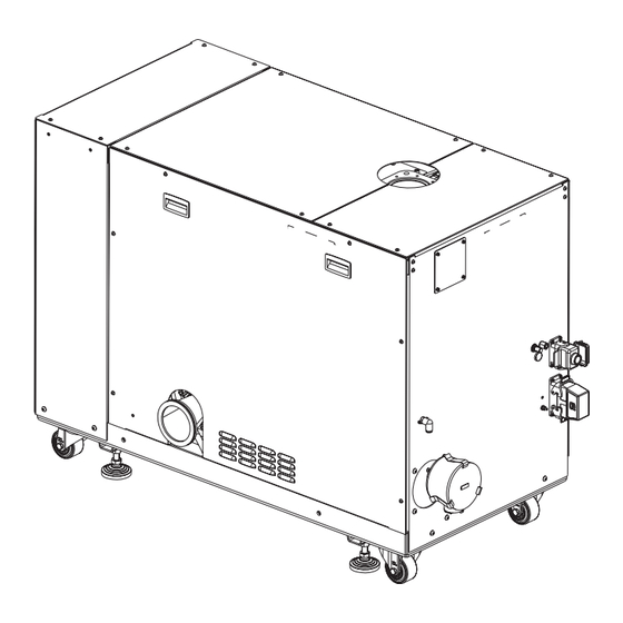
- Page 16 Fig. 1.1 DRYVAC DV 1200 without side covers Description Design The DRYVAC DV 1200 is a dry compressing screw vacuum pump. It is equipped with two pump stages running in parallel. The DRYVAC DV 1200 ATEX cat. 2i is capable of delivering an optimised pumping speed performance also at pressures over 100 mbar.
- Page 17 ■ The pumps are purged with nitrogen for protection against corrosion. The ■ pump flanges have been blanked off with a sealing cap. 4x high-strength crane eyes M16 ■ Intake screen with O-ring ■ 300444302_002_C2 - 12/2019 - © Leybold...
- Page 18 Description Fig. 1.3 Dimensional drawing, dimensions in mm 300444302_002_C2 - 12/2019 - © Leybold...
- Page 19 1) In the case of mains voltage drops or interruptions (brownouts) up to two seconds, operation is maintained and no error message is output. For mains voltages over 460 V this duration may be shorter. 2) Mains power grids: TN Systems, TT systems (earthing at the star point); for other types of mains power grid please consult us. 300444302_002_C2 - 12/2019 - © Leybold...
- Page 20 Purge gas flow shaft seal at nominal setting pressure Inlet (d = 2.0 mm) 170 slm ± 10 % Outlet (d = 0.9 mm) 44 slm ± 10 % Pilot valve gas ballast ~ 0 slm 300444302_002_C2 - 12/2019 - © Leybold...
- Page 21 ) + 572.8 in °C = -190 · lg(p ) + 572,8 in °C > 500 1000 Gaseinlassdruck p in mbar Gas inlet pressure p (mbar) Fig. 1.4 Permissible gas inlet temperature as function of the inlet pressure 300444302_002_C2 - 12/2019 - © Leybold...
- Page 22 Synthetic oil, ester oil, LEYBONOL LVO 210, 5 litres L21005 ProfiNet module for DRYVAC DV / DV-r 112005A35 EtherCAT module for DRYVAC DV / DV-r 112005A36 Ethernet interface board for DRYVAC DV / DV-r 112005A02 Adapter DRYVAC for RUVAC WH 700 112005A03 RUVAC WS(U) 1001...
- Page 23 Operating Instructions. Run regular checks in accordance with these Operating Instructions. Installation and maintenance only in non-explosion hazard areas. 300444302_002_C2 - 12/2019 - © Leybold...
- Page 24 Ensure that it cannot tip over. Due to the castors which have been fitted, the DRYVAC must only be installed on a level surface capable of carrying the weight of the pump as otherwise there exists the danger of the pump rolling away.
- Page 25 AC power supply could be used to supply the variable DC voltage. Resistor 10 ohm Inverter Voltage : 360V (for 200V class) 720V (for 400V class) Time 3 min. or more 40 min. or more Fig. 2.2 Capacitor forming 300444302_002_C2 - 12/2019 - © Leybold...
- Page 26 Kü h lwa s se r A US Cooling water OUT Cooling water IN Kü h lwa s s er E IN Fig. 3.1 Connections for the DRYVAC DV 1200 Installation Placement Place the pump system on a flat and level surface.
- Page 27 Vapours which, when compressed, liq- uefy within the pump must be avoided. The inside chamber of the DRYVAC in contact with the process has been specially designed and manufactured in order to comply with the require-...
- Page 28 Pumping of gases and vapours for which the materials of the pump are not ■ suited, consult Leybold. For a list of materials in contact with the process gases, see Section 1.3 Technical Data. Pumping of condensable vapours without adequately controlling the tem- ■...
- Page 29 Conversions, manipulations and maintenance work by persons not author- ■ ised by Leybold. Accessories which have not been specified by Leybold may only be used ■ after approval by Leybold. The non-conforming use of pump and accessories may result in severe WARNING injury or damage to the components.
- Page 30 The intake lines must be clean. Ensure that no items like welding beads, bolts, nuts, washers, pieces of DANGER wire, for example, enter into the inlet. Observe Safety Information 0.8.3. Connect the intake flange with intake screen and O-ring. 300444302_002_C2 - 12/2019 - © Leybold...
- Page 31 Connect the exhaust line to an abatement system with sufficient throughput, Abatement if required by the process. The DRYVAC pumps will be switched off because of overpressure if the abatement system is too small. Connect the exhaust lines to the pump system‘s exhaust connections. Use bellows to eliminate tension in the line.
- Page 32 Cooling water data for the pump Materials in the cooling circuit of the pump AISI 304, red brass, brass, EPDM, epoxy paint, Feed temperature 5 – 35 °C Feed pressure 2 – 7 bar (g) 300444302_002_C2 - 12/2019 - © Leybold...
- Page 33 15.0 12.0 10.0 The DRYVAC pumps are equipped with a built-in pressure reducer. We rec- ommend not to change the setting. A screen has been built into the pressure reducer protecting the valve seat against coarse contamination, see also Section 5.4 Maintenance.
- Page 34 The third gas inlet inserts the purge gas directly into the pumping chamber (rotor purge). Connect nitrogen or air as purge gas. If in doubt, please contact Leybold. Gas temperature 0 to +50°C.
- Page 35 Possible purge gases are N2 and CDA only. NOTICE The safety always has to be considered (please be careful with air purges and read the safety booklet of Leybold). Exhaust shaft seal purge is running in most of all applications all the time. Rotor purge In most cases not used all the time, often active in specific process steps.
- Page 36 (0.9 mm nozzle) as well, i.e. with pressure rises and ventilation. With the accessory “Permanent Inlet Purge Kit”, the inlet side of the DRYVAC pump may be protected against being contaminated. This is effect- ed by a permanent, comparatively small purge flow (0.5 SLM). For this, the Permanent Inlet Purge Kit is so connected that it is always opened when also the purge gas on the exhaust side (motor side) of the pump is open;...
- Page 37 SRV Safety relief valve 8 bar (g) Check valve L1 L2 L3 400 V Cooling Water Cooling water PRV140 PRV141 Purge- Purge Gas (N2) gas (N2) DRYVAC DV 1200 ATEX cat. 2i Fig. 3.5 Purge gas and switches schematic 300444302_002_C2 - 12/2019 - © Leybold...
- Page 38 The frequency converter may, when deployed in residential areas, cause NOTICE high-frequency interference. In such a case the operator of the unit will have to introduce additional measures for the purpose of suppressing high- frequency interferences. 300444302_002_C2 - 12/2019 - © Leybold...
- Page 39 Nur zur Information FOR INFORMATION O Copper strap, for example Ground bolt Washer Lock washer Nut M 6 Fig. 3.7 Establishing the potential equalisation at the pump casing Nur zur Information FOR INFORMATION ONLY 300444302_002_C2 - 12/2019 - © Leybold...
- Page 40 Before switching on, check the operating conditions for the pump (cooling water, for example). 300444302_002_C2 - 12/2019 - © Leybold...
- Page 41 Fig. 3.9 Profibus connection Leak Search after Installation Observe Safety Information 0.4. DANGER On delivery, the pump is leak tight to 10 mbar·l/s (integral, leak-checked). Leak-check all relevant connections after having installed the pump. 300444302_002_C2 - 12/2019 - © Leybold...
- Page 42 The non-return valve is a fitting for shutting off which is fitted to the exhaust flange of the DRYVAC. It prevents gas from flowing back into the pump. With the pump running, the non-return valve opens more or less wide depending on the gas flow.
- Page 43 The GSD file for Profibus and the manual can be downloaded from www.leybold.com. The GSD file for the versions in this manual is different from the GSD file for the DRYVAC-i versions. Do not mix them up. Safe Connection and Run-up The two screw pumps running in parallel must always run simultaneously.
- Page 44 * 4. All node addresses must be unique. Node addresses 0, 1, and 2 are typically reserved for control, maintenance, and diagnostic equipment. The ERR light will illuminate when 0 or greater than 125 is entered. 300444302_002_C2 - 12/2019 - © Leybold...
- Page 45 * 4. Cannot be used when setting A1-02 (Control Method Selection) to 0 (V/f Control without PG). * 5. The unit is 0.01 A for drives set up to 11 kW in Heavy Duty or Normal Duty and 0.1 A for drives set up for 15 kW and above. 300444302_002_C2 - 12/2019 - © Leybold...
- Page 46 Pump stands still Byte 1 2, 3 Reserved Byte 1 Normal operation (frequency setpoint reached) Byte 1 Drive ready (ready to start, no fault) Byte 1 Alarm Byte 1 Fault Byte 0 8 to F Reserved 300444302_002_C2 - 12/2019 - © Leybold...
- Page 47 20/21 the status data. By activating, respectively deacti- vating the seventh bit in the last byte of the control data, the temperature value in the status data is updated. 300444302_002_C2 - 12/2019 - © Leybold...
- Page 48 1 Pump ready, 1 Normal operation, 0 Reserved, 0 Reserved, 0 Pump at a standstill, 1 Pump is running. MEMOBUS/Modbus Message Area MEMOBUS/Modbus Message Area is not active. Handshaking Register Handshaking Register is not active. 300444302_002_C2 - 12/2019 - © Leybold...
- Page 49 For this reason the DRYVAC DV 1200 must be connect- ed so that it is completely shut down when one of the screw pumps fails.
- Page 50 FOUT FOUT LED Light Off: Anything else then the output frequency is displayed on the data screen * The pump is not intended for LOCAL mode. Default is REMOTE Fig. 4.2 Keys and functions 300444302_002_C2 - 12/2019 - © Leybold...
- Page 51 0 Hz and 120 Hz. Description Parameter Leybold setting in Programming mode Standard output d1-01 120 Hz frequency reference The pre-set limiting parameters, in particular the maximum speed, must DANGER not be changed. Note Safety Information 0.2. 300444302_002_C2 - 12/2019 - © Leybold...
- Page 52 1: During alarm detection 1: During speed agree 1: Drive ready 1: During fault detection 1: Drive ready 1: During alarm detection 1: During alarm detection 1: During fault detection 1: During fault detection 300444302_002_C2 - 12/2019 - © Leybold...
- Page 53 Hz, allowed input range 0 Hz to 120 Hz). Closing of the switch between the digital input S5 and SC will enable the second frequency. The input signal at S5 can be controlled through a timer relay or through the PLC. 300444302_002_C2 - 12/2019 - © Leybold...
- Page 54 Temperature pump 55 °C 60 °C frequency converter 100 FT Gear side (Pt 1000) Temperature Motor PTC — 130 °C Motor prot. relay and frequency converter Frequency converter 105 °C 110 °C frequency converter temperature 300444302_002_C2 - 12/2019 - © Leybold...
- Page 55 If during longer downtimes the system shall remain conditioned for a rapid pumpdown, we recommend to vent in the system with dry nitrogen to atmo- spheric pressure and maintain it in this condition without opening it. 300444302_002_C2 - 12/2019 - © Leybold...
- Page 56 Blow out the cooling water coils with compressed air or Nitrogen (max. 4 bar). Blow into the cooling water inlet port only. Also when storing the pump for longer periods of time the lubricant remains in the pump. 300444302_002_C2 - 12/2019 - © Leybold...
- Page 57 Instructions: “Declaration of Contamination for Compressors, Vacuum Pumps and Components”. Another suitable form is available from www.leybold.com/ -> Downloads -> Download Documents. Attach the form to each pump. This statement detailing the type of contamination is required to satisfy legal requirements and for the protection of our employees.
- Page 58 Fill in new oil at a pump temperature of 15 ºC to 25 ºC. For this use a clean funnel. Make sure to use the right kind of oil. Only use Leybold oil. To prevent the occurrence of sparks by electrostatic charging, only approved oils which exhibit a minimum conductance must be used.
- Page 59 Interlock (optional) Adjustment knob Rotatable outlet pressure indicator (optional, depending on type) Flats for removing the cartridge (for maintenance only) Fig. 5.2 Water pressure reducer (schematic drawing, different types are used in the DRYVAC) 300444302_002_C2 - 12/2019 - © Leybold...
- Page 60 Fig. 1.1. For replacing, unscrew the metal protection basket with cup from the pres- sure reducer. Unscrew the mounting component and detach the used filter cartridge. Fit the parts using a new filter cartridge again. 300444302_002_C2 - 12/2019 - © Leybold...
- Page 61 Power consumption of Like „Pump gets too hot“. Like malfunction „Pump gets too hot“. the motor is too high. Incorrect mains voltage for the motor. Connect the motor to the correct mains voltage. 300444302_002_C2 - 12/2019 - © Leybold...
- Page 62 Connect motor correctly. Motor stator defective. Leybold Service. Motor rotor defective. Leybold Service. Vacuum pump system has a gas leak. Detect leak and seal it. Impeller play is too great. Leybold Service. Bearing defective. Leybold Service. 300444302_002_C2 - 12/2019 - © Leybold...
- Page 63 To remove an alarm or reset a fault, trace the cause, remove it and reset the frequency converter by pushing the Reset key on the operator or cycling the power supply. This lists up the most important alarms and faults only. 300444302_002_C2 - 12/2019 - © Leybold...
- Page 64 50% of the frequency converters rated short circuits or broken insulation. Replace any output current. broken parts. Cable or motor insulation is broken. Reduce the carrier frequency. Excessive stray capacitance at frequen- cy converter output. 300444302_002_C2 - 12/2019 - © Leybold...
- Page 65 Drive The load is too heavy. Check the load. Overload Too much torque at low speed. The overload capability is reduced at low speeds. Reduce the load or increase the fre- quency converter size. 300444302_002_C2 - 12/2019 - © Leybold...
- Page 66 DC Charge The charge circuit for the DC bus is Cycle power to the frequency converter. Circuit Fault broken. Check if the fault reoccurs. Replace the frequency converter if the fault reoccurs. 300444302_002_C2 - 12/2019 - © Leybold...
- Page 67 Check Pt 1000 and connection cable, replace short circuit if required. 100FT Pt 1000 fault Temperature measured with the Pt Check and improve cooling. 1000 reaches > 60 °C. Note “Wait” fault. CMPFT Compen- Contact Leybold sation Fault 300444302_002_C2 - 12/2019 - © Leybold...
- Page 68 LED Tripped is not on: pump is not starting up, there is no overheating con- dition Exhaust The exhaust pressure switch has Check exhaust line. pressure responded, pressure in the exhaust too switch has high (> 1250 mbar). responded 300444302_002_C2 - 12/2019 - © Leybold...
- Page 69 Check the V/f pattern settings. oPE12 Occurs if b1-01 (Frequency Reference) = 3 or b1-02 (Sequence Reference) =3 and Leybold Parameters Lower Level is set and option card is connected. Occurs if following condition is not given: P2-02 < P2-04 < P2-06 < P2-08 < P2-10 < P2-12 <...
- Page 70 Waste oil from vacuum pumps must not be mixed with other substances or materials. Waste oil from vacuum pumps (Leybold oils which are based on mineral oils) which are subject to normal wear and which are contaminated due to the influence of oxygen in the air, high temperatures or mechanical wear must be disposed of through the locally available waste oil disposal system.
- Page 71 EC Declaration of Conformity 300444302_002_C2 - 12/2019 - © Leybold...
- Page 72 Certificates This product has been tested to the requirements of CAN/CSA-C22.2 No. 61010-1, second edition, including Amendment 1, or a later version of the same standard incorporating the same level of testing requirements. 300444302_002_C2 - 12/2019 - © Leybold...
- Page 73 Person to contact: Calibration: Factory-calibr. Phone : Fax: Quality test certificate DIN 55350-18-4.2.1 End user: A. Description of the Leybold product: Failure description: Material description : Additional parts: Catalog number: Serial number: Application-Tool: Application- Process: Type of oil (ForeVacuum-Pumps) : B.
- Page 74 Leybold GmbH Bonner Strasse 498 50968 Cologne GERMANY T: +49-(0)221-347-0 info@leybold.com www.leybold.com...
Need help?
Do you have a question about the DRYVAC and is the answer not in the manual?
Questions and answers